

Siemens QAA2290.EWSC, QAA2290.FWSC, QAA2290.DWSC, APOGEE QAA2290.DWSC, APOGEE QAA2290.EWSC Installation Instructions Manual
...
Installation Instructions
Document No. 129-485
June 13, 2007
Wireless TEC Room Temperature Sensor (Mesh)
CAUTION:
Equipment damage or loss of
data may occur if you do not
follow a procedure as
specified.
Product Description
The APOGEE® Wireless Room Temperature
Sensors eliminate the need to run wire between the
Terminal Equipment Controllers (TECs) and their
respective room temperature sensor. The sensors
communicate with the Field Level Network
Transceivers (FLNXs), mounted at the TECs, that
also support the Wireless Field Level Network
(WFLN).
Caution Notations
Prerequisite
All wiring must conform to NEC and local codes and
regulations.
Product Numbers
QAA2290.EWSC Sensing only*
QAA2290.DWSC Sensing with temperature
display *
QAA2290.FWSC Sensing with override,
setpoint, and temperature
display*
* NOTE: Field selectable Fahrenheit or Celsius.
Accessories
544-643 RTS passkey (to change display to
DIAG mode – may also use
544-643A)
PXA-LITH.P10 Battery (10-pack): 3.6 Volts lithium
AA (Tadiran Batteries part number
TL-4903/S [standard] or SAFT
part number LS14500BA)
540-143 Laptop computer cable (RJ-11 to
DB-9)
Related Products
Wireless Field Level Network (WFLN)
563-054 Field Level Network Transceiver
(FLNX)
563-055 Field Panel Transceiver (FPX)
563-056 Wireless Transceiver Tool (TLX)
Required Tools
Phillips screwdrivers, sizes 1 and 2
Medium and small flat-blade screwdrivers
1/16” hex key
Medium-duty electric drill and 3/16-inch
(4.8 mm) drill bit
Small level and tape measure
NOTE: Depending on the actual installation
(surface mounting) some of these tools
may not be required.
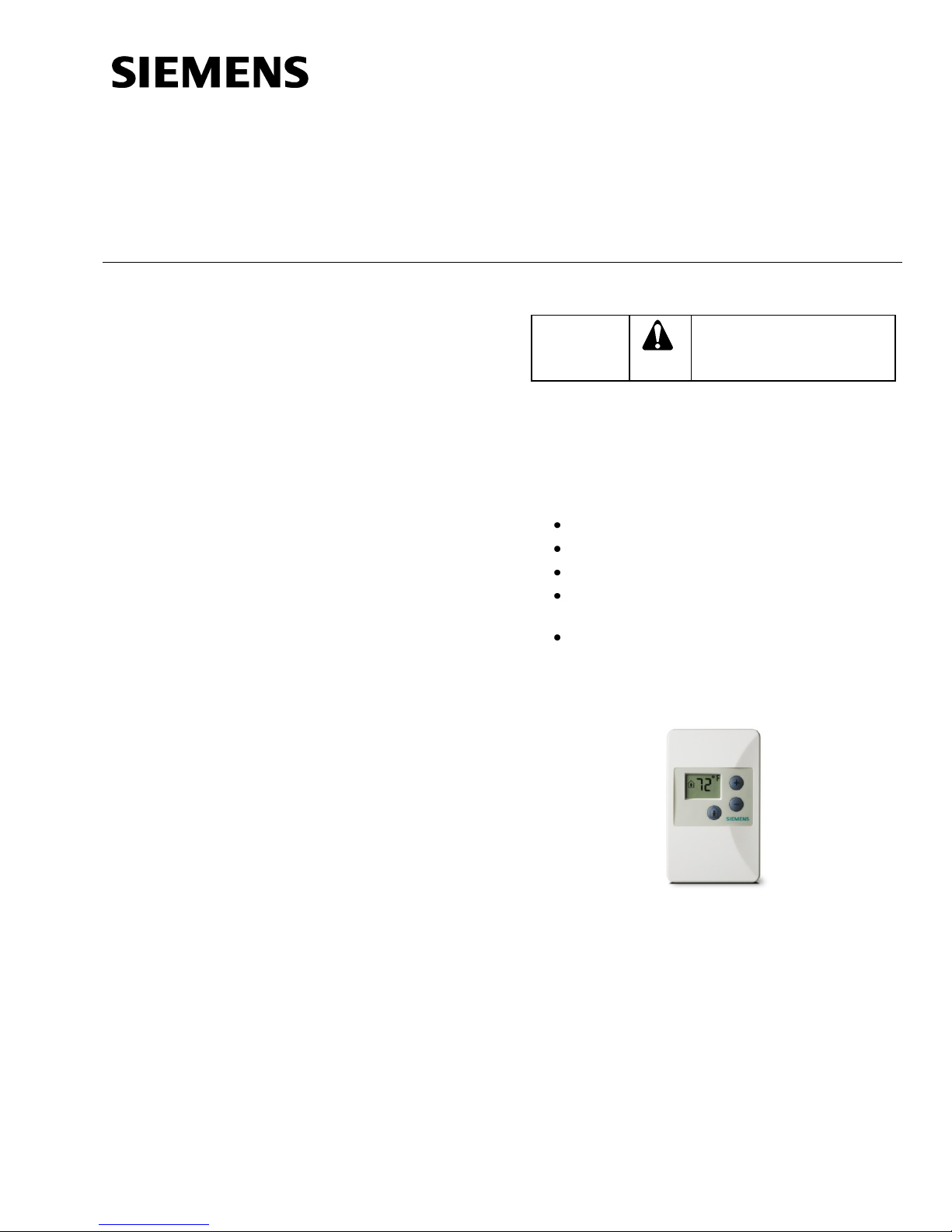
Figure 1. Wireless Room Temperature Sensor.
Installation Accessories
Gym Guard Kit, 141-570, clear plastic,
see document number 155-723.
Expected Installation Time
10 minutes
Item Number 129-485, Rev. BA Page 1 of 3
Document No. 129-485
CAUTION:
Do not mount the WRTS within 3 feet of
other RF devices such as microwave
ovens, Wi-Fi/802.11 access points, etc.
CAUTION:
If a WRTS cannot communicate with its
FLNX for an extended period of time due
to the WFLN not being commissioned or
the FLNX is out of range, remove the
battery to avoid excessive battery drain.
CAUTION:
Over-tightening may cause the sensor
base plate to crack or bend.
Installation Instructions
June 13, 2007
Mounting Information
WRTS Installation
1. Select a location for the WRTS, following the
standard rules for room temperature sensor
placement. Locate the WRTS no further than
100 feet from the nearest FLNX on its WFLN,
ideally in a location where there are no major
RF obstructions (for example, metal or concrete
walls) between the two.
2. Remove the plastic insulating strip between the
battery in the WRTS battery holder (or insert
the battery) to power-up the WRTS.
NOTE: Even though the WRTS is now
powered, it will stay in a low-power
sleep mode until commissioned.
If the WRTS has an LCD panel, the
displayed value will not change until
the WRTS is bound to an FLNX/TEC.
3. Mount the WRTS base plate to the wall.
4. Snap the sensor front to the sensor base plate
by first hooking the sensor front to the top
latches, and then rotating the cover downward
until it latches.
Where the air circulates around it freely (not in
recessed areas or behind doors).
Allow a minimum of 4 inches (10 cm) free
space above and below for proper airflow and
the front cover removal tool.
Away from drafts caused by doors, windows,
outside walls, air registers, return air plenums,
etc.
Away from heat sources such as strong lights,
fireplaces, direct sunlight, etc.
On an inside wall, about 5 feet (1.5 m) above
the finished floor.
The line of sight distance (through walls) to the
nearest FLNX ideally should be less than 100
feet (30 m).
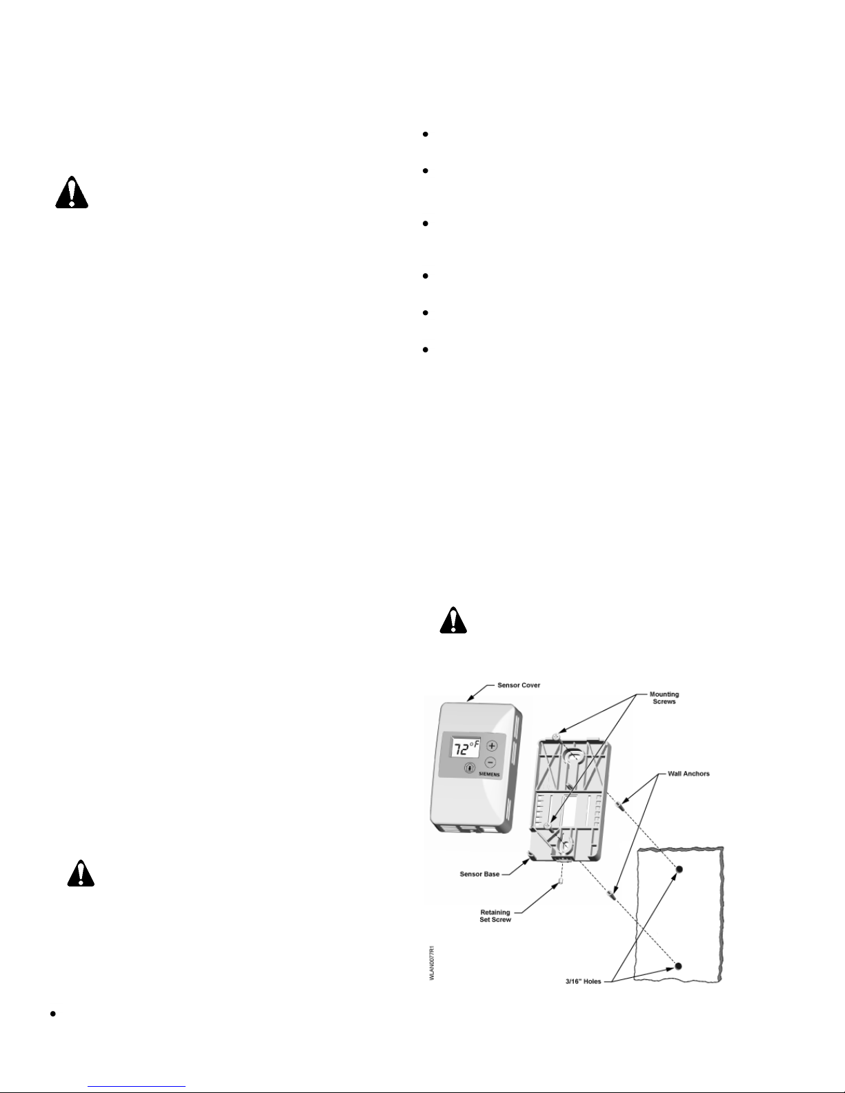
Drywall Base-Plate Mounting (Figure 2)
1. Using the sensor base plate as a template, mark
the top and bottom mounting hole locations for
drywall mounting.
2. Drill two 3/16-inch (4.8 mm) mounting holes and
mount the two wall anchors.
3. Orient the UP arrow on the base plate at the top
and mount on the wall as follows:
a. Level the sensor base plate.
b. Tighten the two mounting screws to the
sensor base plate.
5. Loosen the safety set screw at the bottom of the
base one or two revolutions to lock the cover to
the base. Be careful not to loosen too far as the
screw can be completely removed from the base.
NOTE: There is a perforated label containing
the 16-digit EUID number on the back
of the WRTS. It can be removed and
used for wireless communications with
the WRTS via the TLX.
6. Commission per the WFLN Start-up Procedure
(140-0649)
Always mount the sensor vertically. Locate the
sensor as follows:
Per design specifications, and local regulations.
Page 2 of 3 Siemens Building Technologies, Inc.
The installation is now complete.
Figure 2. Drywall Mounting.
 Loading...