

Siemens QAA2280.xWNC,QAA2280.xWSC,QAA3280.xWNC,QAA2281.xWSC,QAA3280.xWSC Installation Instructions Manual
Installation Instructions
Series 2200 Temperature and Series
TEC
CAUTION
Equipment damage or loss of
specified.
Document No. 129-484
April 17, 2014
3200 Combination RH&T Room Units,
Product Description
These room units allow users to view and adjust
points in the controller using the room unit buttons
and digital display.
They work with various Terminal Equipment
Controllers (TECs) and Actuator Terminal
Controllers (ATECs) offered by Siemens Industry,
Inc. These devices incorporate a solid state or 10K
NTC sensing element to detect temperature (and
humidity for QFA models). The effective sensing and
setpoint range is 55°F to 95°F (13°C to 35°C).
These room units can be mounted on electrical
boxes, stud-type mounting brackets, or drywall.
Obtain the necessary mounting hardware and follow
the appropriate mounting procedures for the type of
installation required.
Product Numbers
QAA2280.xWNC QFA3280.xWNC
QAA2280.xWSC QFA3280.xWSC
QAA2281.xWSC
Expected Installation Time
20 minutes
Required Tools
If using non-terminated or damaged cables, you also
need:
• Phillips sizes 1 and 2 screwdrivers
• Small and medium, flat-blade screwdrivers
• 1/16-inch hex key or 544-643A Passke y
(includes hex bit)
• Medium-duty electric drill
• 3/16-inch (4.8 mm) drill bit
• One-inch (25 mm) hole saw
• Small level
• Tape measure
• Marker or pencil
• Room unit connector tool (RJ-11 crimping
tool – SBT P/N 540-140 or third-party tool)
• Room unit connector kit (SBT P/N 540-141)
Accessories
AQA2200-INTL Room Unit Back Plate (10-pack)
AQA2200-2X4 Room Unit Back Plate (Single)
563-102 GSKT Kit Room Sensor Insulating
Gasket (10-pack)
(For hollow wall in s ta llations)
TEC to Room Sensor Cable
Yellow, 6-pin m ale with RJ -11 jacks on both ends
(Choose 1, a cable may already be installed):
588-100A 25-foot
588-100B 50-foot
588-100C 100-foot
Caution Notations
data may occur if you do not
Item Number 129-484, Rev. JA Page 1 of 3
follow a procedure as
Prerequisites
• Review these instructions before beginning.
• Installed: appropriate field wiring (standard
six-conductor room unit cables, plenum or
non-plenum as required) within the
maximum wiring run length for the individual
equipment controller. The maximum
recommended length is 100 feet (30 m).
• All wiring must comply with Nationa l Electric
Code (NEC) and local regulations.
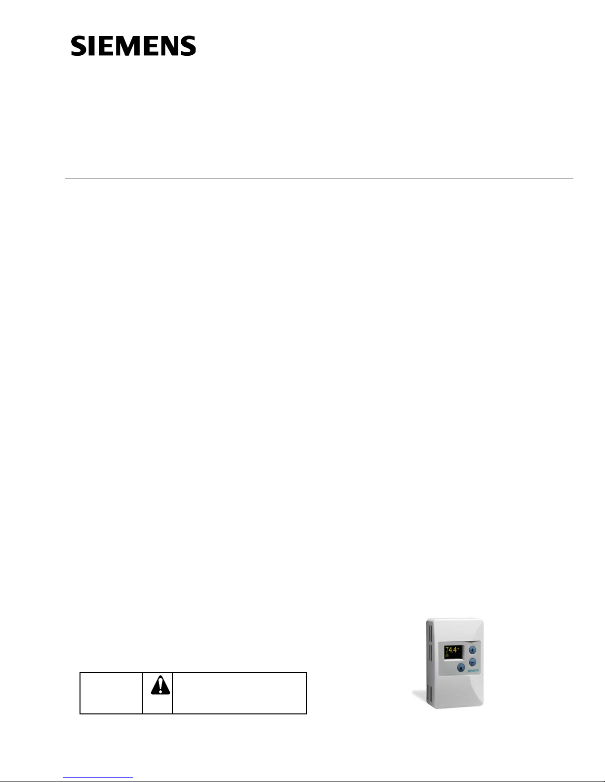
Figure 1. Temperature Room Unit.
Document No. 129-484
Installation Instructions
April 17, 2014
Mounting Information
Always mount the room unit vertically, on a flat wall.
Locate the room unit:
• according to design specif i c ations and loc a l
regulations.
• where the air circulates around it freely (not
in recessed areas or behind doors).
• allowing a minimum of 4 inches (10 cm) free
space above and below for proper airflow,
the hex bit or passkey tool, and the
computer communication cable.
• away from drafts caused by doors, windows,
outside walls, air registers, pipes , return air
plenums, etc.
• away from heat sources such as strong
lights, fireplaces, direct sunlight, etc.
• on an inside wall (preferably), about 5 feet
(1.5 m) above the finished floor, or per code
(ANSI, ADA, or local regulation).
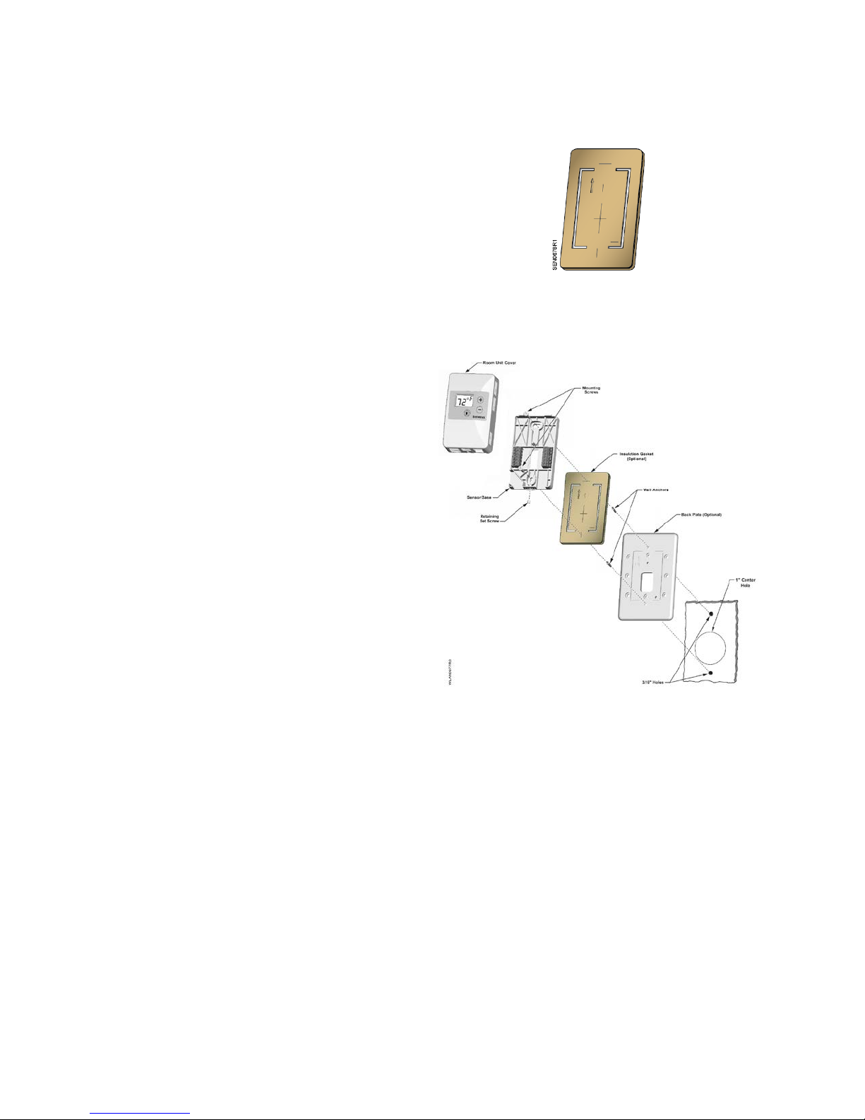
Figure 2. Insulating Gasket.
4. Pull about three inches (75 mm) of the cable
through the hole in the base plate.
Drywall Mounting (No Rough-in),
Typical
1. Mark the center (cable) hole and the mounting
hole locations, using the room unit base pl ate as
a template. See Figure 2.
2. Drill two 3/16-inch (4.8 mm) mounting holes and
mount the two plastic wall anchors flush to
below the wall surface for stable mounting of the
device.
3. Cut a 1-inch (25 mm) center hole with a hole
saw.
NOTE: It is recommended that you use the
optional Insulating Gasket on the back
of the Sensor Base for hollow wall
installations.
When applying the adhesive-backed
gasket to the back of the Sensor Base,
orient the gasket so that the cut-out
arrow portion of the gasket is in the
upper lefthand quadrant of the Sensor
Base. The Sensor Base has an UP
arrow molded into the surface in the
same quadrant location.
NOTE: See Figure 2 for details on optional
Gasket application.
Figure 2. Drywall Mounting (No Rough-in), Typical.
5. Mount the room unit base plate on the wall,
noting the "UP" arrow:
NOTE: If required, position the Back Plate
behind the Room Unit Base, aligning
the top and bottom mounting holes,
prior to mounting to the wall:
a. Install the two mounting screws provided,
but do not tighten.
b. Level the room unit base plate for
appearance.
c. Tighten the two mounting screws to the
room unit base plate.
Page 2 of 3 Siemens Industry, Inc.
 Loading...