

Siemens QPA228.FWNC Series, QPA228.FWSC Series, QAA2280.FWNC, QAA2280.FWSC, QFA3280.FWNC Operator Interface Manual
...Page 1
Operator Interface Guide
Room Unit for TEC, and ATEC
Overview
This document explains the set up and operation of the
Series 2200, and 3200 room unit s. It explains the
various operating modes available and describes the
procedure f or programming the display, according to
user preferences.
These devices are used with BACnet Terminal
Equipment Controllers (TEC), BACnet Actuat or TEC
(ATEC) Controll ers, and BACnet Programmable
Controllers (PTEC).
Product Numbers
Docume nt No. 125- 703
September 19, 2017
QAA2280.FWNC QPA228x.FWSC
QAA2280.FWSC QFA3280.FWNC
QPA228x.FWNC QFA3280.FWSC
Accessories
Description Product Number
Passkey 544-643A
25-foot (7.6 m) cable with
connections
50-foot (15.2 m) cable with
connections
100-foot (30.5 m) cable with
connections
Replacement Relative
Humidity Sensing Element
for QFA and QP A
Replacement Housing Base
(QAA, QF A types)
Replacement Housing Base
(QPA types)
Room Unit Backplate,
10-pack
Power Supply (QPA types)
Wall Gasket, 10-pack
588-100A
588-100B
588-100C
AQF3060
563-102-01
563-120
AQM2200-INTL
AQM2200
563-102 GSKT KIT
Operation
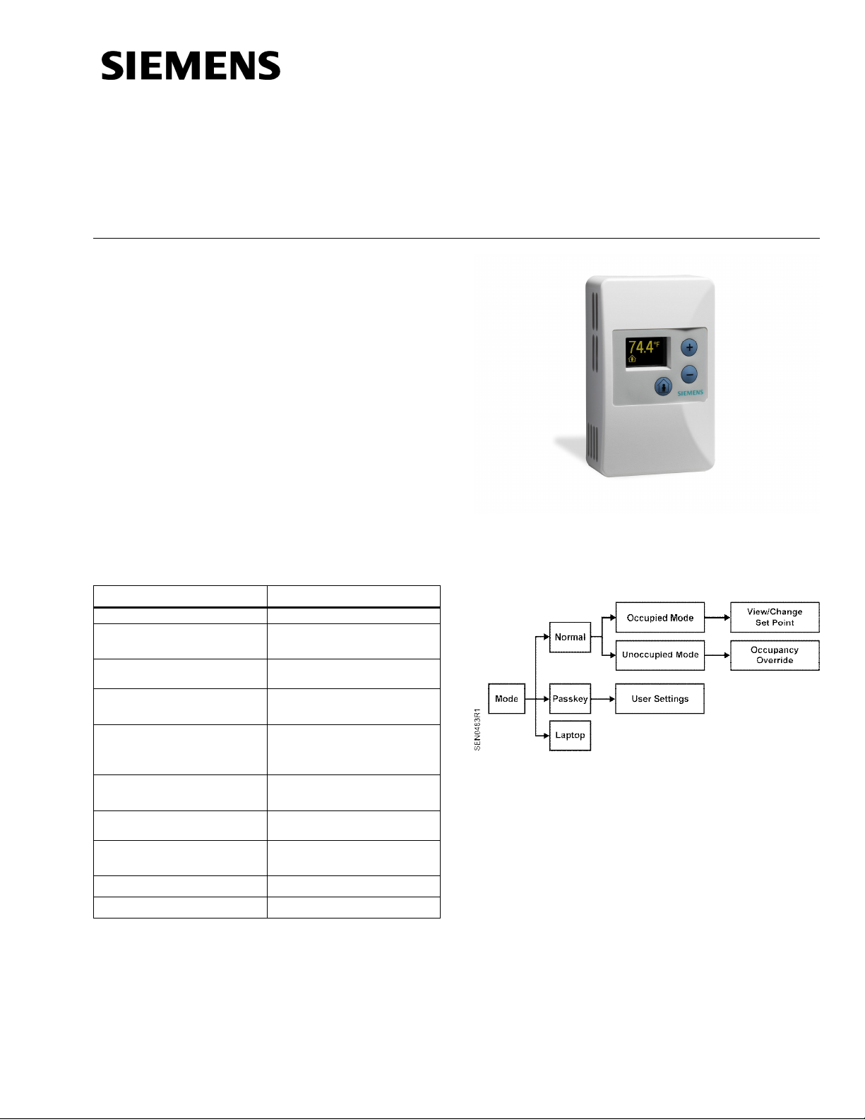
Operation modes
Figure 1. Operation Modes.
Normal Mode
In Normal Mode, the displ ay is updated with
temperature, humi dity, carbon dioxide, and/or occ upied
status (all where appl icable) on a set time cycle.
The display shows tem perature in the desired units (as
set by the cli pable j umper on the PCA). Depending on
the model, the humidity and/or carbon dioxide value(s)
will be displayed as well. When multiple variables need
to be displayed (temperature, relative humidity, and/or
carbon dioxide) the display will cycle through the
required values at a rate of one change every three to
five seconds.
Page 1 of 4
Page 2
Document No. 125-703
Operator Interface Guide
September 19, 2017
Operation modes, Continued
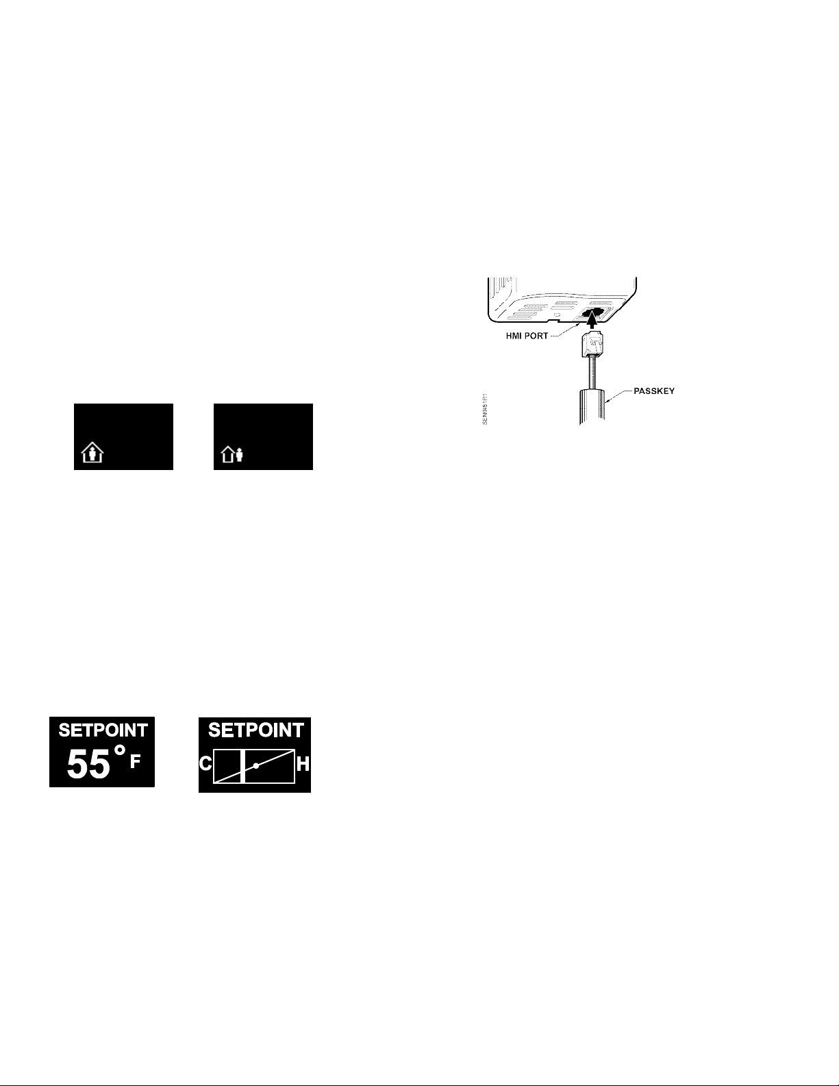
Occupied Mode
If the TEC is currently in Unoccupied Mode (display
shows man outside of the house), pressing the
override button (button designated by an image of a
man inside a house) results in the display showing the
word OCCUPIED and the request is sent to the TEC to
override the unoccupied mode. If the TEC does not get
overridden, and stays in unoccupied mode, the display
on the sensor reverts back to the unoccupied symbol
as soon as possible.
If the TEC is currently in occupied mode, pressing the
override button flashes the word OCCUPIED, and does
nothing else. This functionality is intended solely to let
the user know that the butt on press was recognized.
Occupied Mode Unoccupied Mode
Display Display
Setpoint Adjustment Mode
The temperature setpoint is adjusted by using the plus
and minus buttons. The resulting changes in setpoint
are displayed on t he di spl ay in 1.0°F or 0.5°C
increments.
The setpoint adjustment will display for three seconds.
If, during those three seconds, a setpoint button is
pressed again, the setpoint will be adjusted accordingly
and be displayed, and t he three- second count down will
restart. If there is no user input for more than three
seconds, the room unit will return to Normal Mode.
• Press the plus/minus buttons t o scroll through the
various options available for each parameter to
display the desired option.
• Press the occupancy override button again to
move to the next user adjustable parameter.
• When fi nished, remove the passkey f rom t he HMI
port. User setti ng changes will be saved when the
passkey is removed.
Figure 2. Inserting the Passkey.
NOTE: When the passkey is plugged i n,
communication between the room unit and the
TEC is disabled. See note in Laptop Pass-thru
Mode section for more information.
Settings
• Set Pt Disp - determines how the user views the
temperature setpoint adjustment. The default setting
is NUMERIC, and displ ays in degrees. The user can
select between a NUMERIC and a GRAPHIC
setpoint displ ay.
• Set Pt Min - determines the minimum temperature
setpoint value. The default setting is 55°F (12.5°C).
The user selects the minimum setpoint the room unit
should request. The setpoint limit is ultimately
defined in the controller. If the setpoint is displayed
graphically as a sliding bar, this sets the left end of
the slider bar. The limits are 55°F to the Set Pt Max
value. The adj ustm ent step size is 1°F (0.5°C).
Passkey Mode
Insert the passkey in the sensor HMI (Human-Machine
Interface) port to setup all of the user functionality listed
below. For each parameter, use the following
sequence:
• Press the occupancy override button to edit the
parameter.
Page 2 of 4 Siemens Industry, Inc.
• Set Pt Max - determines the maximum temperature
setpoint value. The default setting is 95°F (35°C).
The user selects the max imum setpoint the sensor
should request. The setpoint limit is ultimately
defined in the controller. If the setpoint is displayed
graphically as a sliding bar, this sets the right end of
the slider bar. The limits are Set Pt Min to 95°F
(35°C). The adjustment step size is 1°F (0.5°C).
Page 3

Document No. 125-703
Operator Interface Guide
September 19, 2017
• Disp Temp? – determines whether the temperature
value should be displayed. The default value is YES.
• Disp RH? – determines whether the humidity val ue
should be displayed. The default value is YES, if the
device is a combination temperature/humidity or
temperature/ humi dity, CO2 room unit. (This option is
conditional based on the presence of humidity
measurement capability, and only offered with
QFA3x80.F or QPA2x84. F types.)
• Disp CO2? – determines whether the carbon
dioxide value should be displayed. The default value
is YES, if the device is a CO2 Room Unit. (This
option is conditional based on the presence of CO
measurement capability, and only offered with
QPA2x84.F types.)
• Disp Occ? – determines whether the occupancy
status should be displayed. The default value is YES
if the device offers occupanc y override capability.
NOTE: This does not enable/disable the Occupancy
override button functionality, just the display of the
occupancy status.
• T Cal – allows the user to field calibrate the
temperature display and output through a bias
adjustment. The default value is + 0°F. Adjustments
can be made between -5°F and + 5°F, in 0.5°F
increments.
• RH Cal – allows the user to field calibrate the
humidity display and output through a bias
adjustment. The default value is + 0%. Adjustments
can be made between -5% and + 5%, in 0.5%
increments. (This option is conditional based on t he
presence of humidity measurement capability, and
only offered wit h QFA3x80.F or QPA2x84.F types.)
• Scr Saver – allows the user to activat e or
deactivat e the display screen saver. Available
options are: NONE, OFF, and FADING. The
default value is NONE.
− NONE – The display operates at the
programmed brightness level without any
interrupti on.
− Off – The display will turn off aft er 30 seconds.
Any button press will wake it up (without doing
anything else), and then the device will operate
in Normal Mode for 30 seconds until the display
turns off again.
2
− Fading – Within 30 seconds of no operator
interacti on, the entire display will fade to a
display brightness of 1. The display will operate
at this brightness until the user presses a
button. At that time, the programmed display
brightness will be restored.
• Factory Defaults - allows the user to reset all
parameters to fac tory defaults. The default is NO.
Available options for this parameter are YES and
NO.
Parameter Default Value
Set Pt Disp NUMERIC
Set Pt Min 55°F (13°C)
Set Pt Max 95°F (35°C)
DISP Temp? YES
Disp RH? YES
Disp CO2? YES
Disp Occ? YES
T Cal + 0°F (0°C)
RH Cal + 0%
CO2 Cal +0 PPM
Brightness 5
Scr Saver NONE
Factory Defaults NO
• CO2 Cal – allows the user to field cali brate t he
carbon dioxi de displ ay and output through a bias
adjustment. The default value is +0 parts per million
(PPM). Adjustments can be made between -175 and
+ 50 PPM, in 5 PPM increments. (This option is
conditional based on the presence of CO
2
measurement capability, and only offered with
QPA2x84.F types.)
Laptop Pass-thru Mode
To communicat e with the TEC using Datamate Base,
Datamate Advanced, or Microsoft Windows
TM
Controll er Interf ace Software (WCIS), connect a PCcompatible cable (see Accessories) from a lapto p to
the sensor HMI port at the bottom of the room unit.
This puts the room unit in laptop mode, which
deactivat es all buttons and di spl ays LAPTOP on the
• Brightness – allows the user to adjust the display
brightness. Valid values are 1, 2, 3, 4, 5, 6, 7, 8, 9
and 10, with 1 being dimmest and 10 bei ng
brightest. The default setting is 5.
display. In this mode, the controller communicates only
with the laptop and still allows the temperature,
humidity, or CO2 values (where applicable) to be
updated in the controller. The room unit controls
communication, and updates values every 10 seconds.
The room unit returns to Normal Mode once the cable
is disconnected.
Siemens Industry, Inc. Page 3 of 4
Page 4

Document No. 125-703
Operator Interface Guide
September 19, 2017
NOTE: The Room Unit (Firmware Revi si on 016 or
lower) will stop updating ROOM TEMP, RM
STPT, and OVRD if a passkey or laptop cable
is connected to the Room Unit. This issue will
affect the normal commissioning process,
because the Specialist cannot leave the HMI
cable connected to the Room Unit to monitor
the TEC’s control. This affects all Series 2200
and 3200 models.
Furthermore, if the TEC is initialized, power is
cycled (which has the same effect as
initializing the TEC) or the Application
(subpoint 2) i s commanded to another value,
the following will occur:
• The RM TEMP will read and control to 57°F
(12°C).
• The RM STPT with read and control to 98°F
(37°C).
Once the passkey or HMI cable or passkey is
disconnected, t he ROOM TEMP will update
within 10 seconds. The RM STPT will not
update until t he setpoint setting is changed on
the Room Unit or until the Room Unit cycles
power.
The Room Unit (Firmware Revi si on 029 or
higher) in combinat ion with new release TEC
products ROOM TEMP, RM STPT, and OVRD
will be updated if a passkey or laptop cable is
connected to the Room Unit, but the buttons
will not work. New release TEC P roducts Use
a SENSOR SEL point that allows the TEC to
see all inputs from the Digital Room Sensor,
the default setting does not allow the TEC to
see the points.
Set-up of Displayed Temperature
Units
The factory default for displayed temperature units is
°F. To change the display to °C mode, snip the wire
jumper on the back of the PCB (the visible side when
the unit is taken off the wall).
Figure 3. Jumper Location.
Error Messages
Message Meaning
NO TEC
NO
SENSOR
0xx
No communication with TEC. This error will
display on the lower right (icon) section of
the display, and the upper portion of the
display should continue to display
temperature v alues (and/or humidity and
CO2 values where applicable).
Or a bad crimp on the RJ11 cable
connection.
NOTE: This error will display whenever
TEC subpoints are not available or when
the TEC (or its subpoints) are not
responding to commands. The default HMI
baud rate on the TEC is 1200, but the
room unit baud rat e i s self-adjusting.
No temperature (or humidity or CO2 where
applicable) sensor detected on the PCA.
This error will display until the error is
corrected. This message might also
display if the wrong controller-to-room unitcable is used or if the replacement sensor
element is incorrectly installed on the PCA.
Room unit firmware revision, where X is a
number between 0 and 9. For Room Unit s
(Revision 016 and lower) this is visible
upon power-up for a f ew seconds until
communication is established with the TEC
or ATEC. For Revision 029 and higher, this
is visible for a few seconds upon power-up
and when the laptop cable is disconnected.
Information in this publication is based on c urrent specifications. Th e company reserves the right to make changes in specifications and models
as desig n improvements ar e i ntroduced. Produc t or company names mentioned herein may be the tr ademarks of their respecti ve owners.
© 2017 Siemens Industry, Inc.
Siemens Industry, Inc.
Building Technologies Division
1000 Deerfield Parkway
Buffalo Grove, IL 6 0089-4513
USA
+1-847-215-1000
Your feedback is important to us. If you have
comments about this document, please send them
toSBT_technical.editor.us.sbt@siemens.com
Document No. 125-703
Printed in the USA
Page 4 of 4
 Loading...