

Siemens QAA2212.*W*N, QAA2220.*W*N, QAA2232.*W*N, QAA2221.*W*N, QAA2235.*W*N Installation Instructions Manual
...Page 1
Installation Instructions
Docume nt No. 129-477
Series 2200 Room
Units
CAUT
ION
Novemb er 15, 2017
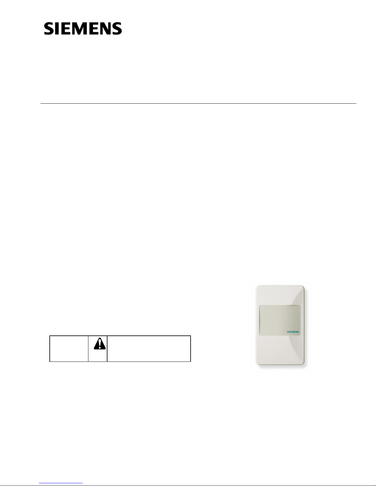
Product Description
These room units measure t emperature in the
occupied space in which they are installed. Models
with display allow users to view the measured
temperature value. A version with temperature
setpoint adjustment is also offered.
The effective sensing and setpoint range is 55°F to
95°F (13°C to 35°C).
These room units can be mounted on electrical
boxes, stud-type mounting brackets, or drywall.
Hardware is included for installation on drywall or on
a 2” × 4” electrical box.
Product Numbers
QAA2212.xWxN QAA2232.xWxN
QAA2220.xWxN QAA2235.xWxN
QAA2221.xWxN QAA22SS.xWxN
QAA2230.EWxN
Accessories
AQA2200-INTL Room Unit Back Plate (10-pack)
Required Tools
• Sizes 1 and 2 Phillips screwdrivers
• Small and medium flat-blade screwdrivers
• 1/16-inch hex key
• Medium-duty electric drill
• 3/16-inch (4.8 mm) drill bit
• One-inch (25 mm) hole saw
• Small level
• Tape measure
• Marker or pencil
Prerequisites
• Review these instructions before beginning.
• Installed: appropriate field wiring within the
maximum wiring run length for the individual
equipment controller. The maximum
recommended length is 100 feet (30 m).
• All wiring must comply with National Electric
Code (NEC) and local regulations.
563-102 GSKT KIT Room Sensor Insulating
Gasket (10-pack)
(For hollow wall installations)
Caution Notations
Equipm ent damage or l oss of
data may occur if you do not
follow a procedure as
specified.
Expected Installation Time
20 minutes
Item Number 129-477, Rev. JA
Figure 1. Typical Temperature Room Unit.
Page 1 of 4
Page 2
Document No. 129-477
Installation Instructions
November 15, 2017
Mounting Information
Always mount the room unit vertically.
Locate the room unit:
• according to design specifications and local
regulations.
• where the air circulates around it freely (not in
recessed areas or behind doors).
• allowing a minimum of 4 inches (10 cm) free
space above and below for proper airflow, the
front cover removal tool, and the computer
communicati on cabl e.
• away from drafts caused by doors, windows,
outside walls, air registers, pipes, return air
plenums, and so on.
• away from heat sources such as strong lights,
fireplaces, direct sunlight, and so on.
• on an inside wall (preferably), about 5 feet
(1.5 m) above the finished floor, or per code
(ANSI, ADA, or local regulation).
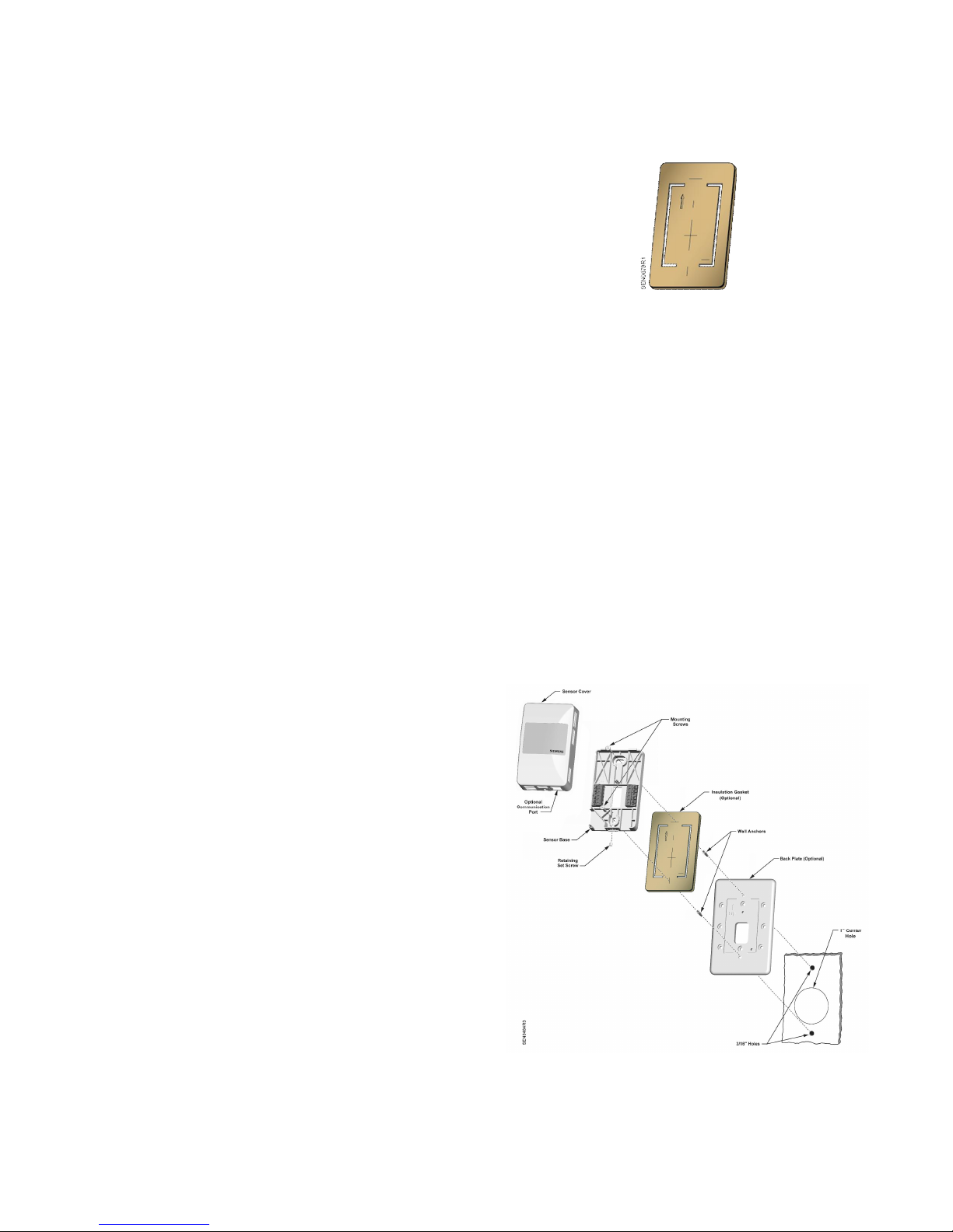
Drywall Mounting (No Rough-in),
Typical
Base Plate Mounting and Wiring
1. Mark the center (cable) hole and the mounting
hole locations, using the temperature sensor base
plate as a template. See Figure 3.
Figure 2. Insulating Gasket.
4. Pull about three inches (75 mm) of the cable through
the hole in the base plate.
5. Mount the room unit base plate on the wall, noting the
UP arrow:
NOTE: If required, position the back plate behind the
room unit base, aligning the top and bottom
mounting holes, prior to mounting to the wall:
a. Install the two mounting screws provi ded, but do
not tighten.
b. Level the room unit base plate for appearance.
c. T ighten the two m ounting screws to the room unit
base plate.
6. Cut the cable, leaving about three inches (75 mm) on
the room unit side of the drywall. Ensure that pin
Number 1 connects to the same wire at each end of
the cable.
2. Drill two 3/16-inch (4.8 mm) mounting holes and
mount the two plastic wall anchors flush to below
the wall surface for stable mounting of the dev ice.
3. Cut a 1-inch (25 mm) center hole with a hole saw.
NOTE: It is recommended that you use the
optional insulating gasket on the back of
the Sensor Base for hollow wall
install ati ons.
When applying the adhesive-backed
gasket to the back of the Sensor Base,
orient the gasket so that the cut-out
arrow portion of the gasket is in the
upper left-hand quadrant of the Sensor
Base. The Sensor Base has an UP
arrow molded into the surface in the
same quadrant location (see Figure 6).
NOTE:See Figure 2 for details on optional Gasket
application.
Figure 3. Drywall Mounting (No Rough-in), Typical.
Page 2 of 4 Siemens Industry, Inc.
Page 3

7. Terminate the wires to the termination blocks on the
CAUTION:
room unit's base plate. (See Figure 6.)
8. Feed the extra cable back through the hole.
Sensor Set-up
Document No. 129-477
Installation Instructions
November 15, 2017
Figure 5. Changing Display to °C.
3. Snap the room unit cover to the base plate by first
hooking the room unit’s front to the top latches, and
then rotating the cover downward until it latches.
Figure 4. Circuit Board
(Located inside Room Unit Cover.
1. If the device has a switch, determine if voltage or
current output is needed.
• For current, set the switch in t he down positi on
(I).
• For voltage, set t he switch in the up position (V).
NOTE: The output setting applies to all outputs
(temperature, and setpoint).
2. If selecting voltage, set the jumper:
• Use the top and middle pins for 0 to 5V.
• Use the bottom and middl e pi ns f or 0 t o 10V.
NOTE: If the jumper is missing or removed, the
output voltage will default to
0 to 10V.
NOTE: The factory default for displayed temperature
units is °F. To change the display to °C, snip the
wire jumper (0 Ohm resistor R64) on the back of
the PCA.
4. Loosen the safety set screw at the bottom of the
base one or two revoluti ons to lock the cover to the
base. Be careful not to loosen too far as the screw
can be completely removed from the base.
Electrical Box and Rough-in
Mounting, Typical
1. If a locator is attached to the rough-in device,
remove the locator by removing the two screws and
lightly rocking the locator to pull it free.
2. Untie the twist tie and pull about three inches
(75 mm) of the room unit cable through the hole in
the base plate.
3. Mount the room unit base plate on the wall, noting
the UP arrow:
NOTE: If required, position the back plate behind
the room unit base, aligning the top and
bottom mounting holes, prior to mounting
to the wall:
a. Install the two room unit mounting screws
provided, but do not tighten.
b. Level the room unit base plate for appearance
only.
c. Ti ghten the two mounting screws to the room
unit base plate.
Siemens Industry, Inc. Page 3 of 4
Over-tightening may cause the room unit
base plate to crack or bend.
4. Continue with Drywall Mounting (No Rough-in),
Typical, Steps 6 through 8, and Sensor Set-up.
Page 4

Document No. 129-477
CAUTION:
CAUTION:
Sensing Only, Not Sel
ectable
Sensing Only, Selectable
Display, Selectable
Installation Instructions
November 15, 2017
To prevent equipment dam age, do the
following:
If the room unit is powered by AC:
• AC Supply must be type NEC Class 2
and earth grounded at the secondary
neutral.
• Room unit ACN (GND) must be
connected to the controller common.
• If the controller has a float ing common,
that common must be connec ted to the
same earth ground poi nt as the
controller A C supply.
If the room unit is powered by isolated DC:
• Where power is current limited up to
300 mA, it is not required to earth
ground the controller isolated common.
• Room unit DC-(GND) must be
connected to the controller common.
Figure 6. Typical Wiring Base.
(All terminals may not be present.)
Pin No. Function
2 GND
3 TEMP
Follow manufacturer’s Installation
Instructions and Wiring Guidelines for
connecting the controller to the room unit.
For Siemens Controll ers:
1 DC+ or ACH
2 DC- or ACN (GND)
3 Temp Output
5* Passive Temp
6* Passive Temp Common
• APOGEE Controllers with common
already earth grounded are TXIO
used on PXC Modular, PXC Compact
36 Expansion and P1 BI M or PTM
used on MBC and RBC. These do not
require the earth ground wire to be
connected to the controller.
• APOGEE Controllers with floating
common are PXC Compact 16/ 24/36,
1 DC+ or ACH
2 DC- or ACN (GND)
3 Temp Output
5* Passive Temp
6* Passive Temp Common
7 Setpoint Out put
8 Override
9 Override Common
MEC, PXM, LON TEC and PPM.
These require the earth ground wire
to be connected to the controller.
NOTE: If active temperature (0 to 5V/0 to 10V/4 to
20 mA) (Pin 3) rather than passive/resistive
temperature is used, Passive Temp Common
(Pin 6) does not need to be termi nated.
The install ation is now complete.
Information in this publication is based on curr ent specifications. The company reserves the rig ht to make changes in specifications and models as
design i mprovements are introduced. APOGEE is a r egistered trademark or Siemens Industry, Inc. Other pr oduct or company names mentioned herein
may be th e t rademarks of their respective owners. © 2015 Siemens Industry, Inc.
Siemens Industry, Inc.
Building Technologies Division
1000 Deerfield Parkway
Buffalo Grove, IL 60089
USA
+ 1 847-215-1000
Your feedback is i mportant to us . If you have
comments about this document, please send them
toSBT_technical.editor.us.sbt@siemens.com
Document No. 129-477
Printed in the USA
Page 4 of 4
 Loading...