

Siemens PXC-16 Compact, PXC Compact Series, PXC-24 Compact, PXC-36 Compact, PXC Modular Series Technical Reference Manual
Page 1

PXC Compact Series
Technical Reference Manual
145-172
Building Technologies
2018
-09-25 Restricted
Page 2

Copyright Notice
2
| 100
Siemens Industry, Inc.
Technical Reference Manual
145-172
Building Technologies
Restricted
2018-09-25
Copyright Notice
Notice
Document information is subject to change without notice by Siemens Industry, Inc.
Companies, names, and various data used in examples are fictitious unless otherwise
noted. No part of this document may be reproduced or transmitted in any form or by
any means, electronic or mechanical, for any purpose, without the express written
permission of Siemens Industry, Inc.
Warning
This equipment generates, uses, and can radiate radio frequency energy. If equipment
is not installed and used in accordance with the instructions manual, it may cause
interference to radio communications. Equipment has been tested and found to comply
within the limits for a Class B digital device pursuant to Part 15 of the FCC rules. These
limits are designed to provide reasonable protection against such interference when
operated in a commercial environment. Operation of this equipment in a residential
area is likely to cause interference. Residential area equipment users are required to
take whatever measures necessary to correct the interference at their own expense.
Service Statement
Control devices are combined to make a system. Each control device is mechanical in
nature and all mechanical components must be regularly serviced to optimize their
operation. Siemens Industry, Inc. branch offices and authorized distributors offer
Technical Support Programs that will ensure continuous, trouble-free system
performance.
For further information, contact your nearest Siemens Industry representative.
Copyright 2018 Siemens Industry, Inc.
FCC Regulations
The manual for an intentional or unintentional radiator shall caution the user that
changes or modifications not expressly approved by the party responsible could void
the user’s authority to operate the equipment.
For a Class B digital device or peripheral, the instructions furnished the user shall
include the following or similar statement, placed in a prominent location in the text of
the manual:
NOTE: This equipment has been tested and found to comply with the limits for a Class
B digital device, pursuant to part 15 of the FCC Rules. These limits are designed to
provide reasonable protection against harmful interference in a residential installation.
This equipment generates, uses and can radiate radio frequency energy and, if not installed and used in accordance with the instructions, may cause harmful interference to
radio communications. However, there is no guarantee that interference will not occur
in a particular installation. If this equipment does cause harmful interference to radio or
television reception, which can be determined by turning the equipment off and on, the
user is encouraged to try to correct the interference by one or more of the following
measures:
●
Reorient or relocate the receiving antenna.
●
Increase the separation between the equipment and receiver.
●
Connect the equipment into an outlet on a circuit different from that to which the
receiver is connected.
●
Consult the dealer or an experienced radio/TV technician for help.
Page 3

Copyright Notice
3 |
100
Siemens Industry, Inc.
Technical Reference Manual
145-172
Building Technologies
Restricted
2018-09-25
To the Reader
Your feedback is important to us. If you have comments about this manual, please
submit them to: SBT_technical.editor.us.sbt@siemens.com
Credits
APOGEE, APOGEE GO, InfoCenter Administrator, InfoCenter Report Manager,
InfoCenter Server, InfoCenter Suite, and Insight are registered trademarks of Siemens
Industry, Inc.
Desigo® and Desigo® CC™ are registered trademarks of Siemens Schweiz AG.
Other product or company names mentioned herein may be the trademarks of their
respective owners.
Printed in the USA.
Cyber security disclaimer
Siemens provides a portfolio of products, solutions, systems and services that includes
security functions that support the secure operation of plants, systems, machines and
networks. In the field of Building Technologies, this includes building automation and
control, fire safety, security management as well as physical security systems.
In order to protect plants, systems, machines and networks against cyber threats, it is
necessary to implement – and continuously maintain – a holistic, state-of-the-art
security concept. Siemens’ portfolio only forms one element of such a concept.
You are responsible for preventing unauthorized access to your plants, systems,
machines and networks which should only be connected to an enterprise network or
the internet if and to the extent such a connection is necessary and only when
appropriate security measures (e.g. firewalls and/or network segmentation) are in
place. Additionally, Siemens’ guidance on appropriate security measures should be
taken into account. For additional information, please contact your Siemens sales
representative or visit
https://www.siemens.com/global/en/home/company/topic-
areas/future-of-manufacturing/industrial-security.html.
Siemens’ portfolio undergoes continuous development to make it more secure.
Siemens strongly recommends that updates are applied as soon as they are available
and that the latest versions are used. Use of versions that are no longer supported,
and failure to apply the latest updates may increase your exposure to cyber threats.
Siemens strongly recommends to comply with security advisories on the latest security
threats, patches and other related measures, published, among others, under
https://www.siemens.com/cert/en/cert-security-advisories.htm
.
Page 4

Siemens Industry, Inc.
Technical Reference Manual
145-172
Building Technologies
Restricted
2018-09-25
4
| 100
Table of Contents
Cyber security disclaimer ................................................................................................ 3
Compact Series Product Overview ............................................................................. 7
Compatibility with the APOGEE Automation System ...................................................... 7
BACnet Protocol Compatibility .............................................................................. 8
TCP/IP Protocol Compatibility ............................................................................... 8
Required IP Addresses .......................................................................... 8
Device Registration ................................................................................ 8
Address Assignment .............................................................................. 8
System Program .............................................................................................................. 9
Minimum Firmware Revision Required ............................................................... 10
License Manager ................................................................................................. 10
Purpose of Licenses ............................................................................ 11
Supported Point Types .................................................................................................. 12
PXC Compact Series, Rev 1 Hardware, Point Types ......................................... 14
16- and 24-Point Compact Series Diagram ................................................................... 15
36-Point Compact Series Product Diagram .................................................................. 17
Hardware Features ................................................................................................... 19
24 Vdc External Sensor Power Source ......................................................................... 20
Shield Termination .............................................................................................. 20
Custom Sensor Support ...................................................................................... 21
Memory .......................................................................................................................... 21
Flash Read-Only Memory (Flash ROM) .............................................................. 22
Compressed ROM ............................................................................... 22
Auto-Restore and Database Backup to Flash ..................................... 22
Auto Save ............................................................................................ 23
File System Operations........................................................................ 23
Random Access Memory (RAM) ......................................................................... 23
Compact Series Backup Batteries ................................................................................. 23
AA Battery ........................................................................................................... 24
AA Battery ........................................................................................................... 25
Coin Cell Battery ................................................................................................. 26
Coin Cell Battery ................................................................................................. 27
Memory Size and Typical Battery Backup Time ................................................. 28
Compact Series Specifications ...................................................................................... 28
Sensor Limits ....................................................................................................... 33
Communication Connections ......................................................................................... 33
HMI and Tool Ports ............................................................................................. 34
Pin-Out Diagrams for HMI Connectors ................................................ 35
10B/100B Ethernet Port ...................................................................................... 36
Page 5

5 |
100
Siemens Industry, Inc.
Technical Reference Manual
145-172
Building Technologies
Restricted
2018-09-25
RS-485 Port ......................................................................................................... 36
FLN Support ......................................................................................... 37
PXC Compact on P1 ............................................................................ 38
PXC Compact on P1 ............................................................................ 38
Virtual AEM .......................................................................................... 38
Virtual AEM .......................................................................................... 38
USB Host Port ..................................................................................................... 39
TX-I/O Island Bus ................................................................................................ 39
HOA (Hand-Off-Auto) Upgrade Kits .............................................................................. 39
HOA Specifications ............................................................................................. 40
Hardware Features.............................................................................................. 40
Default Mapping .................................................................................................. 40
Communication ................................................................................................... 41
Using the HOA Switches ..................................................................................... 42
PXC Compact on P1 ..................................................................................................... 44
What is a PXC Compact on P1? ......................................................................... 44
P1 Mode Application ........................................................................................... 45
P1 Mode Operation ............................................................................................. 46
P1 Mode Enhanced Field Panel Point Team ...................................................... 47
Tips for P1 Mode ................................................................................................. 48
Backing up and Restoring the PXC Compact Database ..................... 48
Loading Applications with WCIS .......................................................... 48
Merging Multiple Applications into One .ISB File ................................. 48
Using the P1 COMM Panel Team Point .............................................. 48
Miscellaneous ...................................................................................... 49
Referencing Points on the PXC Compact on P1 ................................. 49
Procedures for Advanced Features .................................................................... 49
Adding Unused I/O for PXC Compact on P1 (Optional) ...................... 49
Changing the Point Team Descriptor After Database Conversion ...... 50
Defining an L2SL from a PXC Compact on P1 into the Host Field
Panel 50
Identifying the Hardware Model Used in an Application Design .......... 51
Making Changes to the Original PXC Compact on P1 Database ....... 52
Program to Allow LPACI Points to Count Over the LAO Maximum
Value 53
Real Time Applications in a PXC Compact on P1 ............................... 54
Synchronizing System Time in a PXC Compact on P1 ....................... 58
Default Applications ............................................................................................ 59
Point Database for Application 3916 ................................................................... 60
Point Database for Application 3924 ................................................................... 61
PXM10S/T Product Overview and Description ............................................................. 62
Product Features ................................................................................................. 63
Communication Connections ............................................................... 63
Requirements ...................................................................................................... 63
Page 6

Siemens Industry, Inc.
Technical Reference Manual
145-172
Building Technologies
Restricted
2018-09-25
6
| 100
Application Menus ............................................................................................... 64
Operator Display Specifications .......................................................................... 64
Operator Display Layout...................................................................................... 65
Operator Display Menu Tree ............................................................................... 68
Login and Logoff .................................................................................................. 68
Logging In ............................................................................................ 69
Logging Off .......................................................................................... 73
Navigation Menu ................................................................................................. 74
Alarms Application Menu..................................................................................... 75
Points (Command and Release) Application Menu ............................................ 77
Point Monitor Application Menu .......................................................................... 78
Login Application Menu ....................................................................................... 79
Settings Application Menu ................................................................................... 80
Unitary Equipment Controller ........................................................................................ 81
Unitary Equipment Controller Specifications ....................................................... 83
Compact Series Smoke Control Application Requirements ....................................... 86
Example ALN Configuration for Smoke Control Applications ....................................... 87
Service Information .................................................................................................. 88
Electrostatic Discharge .................................................................................................. 88
Ordering Replacement Parts ......................................................................................... 88
Replacing the Batteries ................................................................................................. 88
Reinstalling the Mounting Tabs ..................................................................................... 89
Troubleshooting Compact Field Panels ........................................................................ 90
Analog Input and Analog Output Points .............................................................. 90
BATT LOW LED .................................................................................................. 91
RUN LED ............................................................................................................. 92
TX and RX LEDs ................................................................................................. 92
Communication ................................................................................................... 93
Display ............................................................................................................. 93
Errors ............................................................................................................. 94
Troubleshooting the TX-I/O Island Bus ......................................................................... 94
Troubleshooting the LCD Panel Indications ........................................................ 95
Resetting an I/O Module to Factory Settings ...................................................... 97
Replacing a TX-I/O Plug-in Module ..................................................................... 98
Replacing a TX-I/O Module Assembly ................................................................ 98
Page 7
Compact Series Product Overview
Compatibility with the APOGEE Automation System
7 |
100
Siemens Industry, Inc.
Technical Reference Manual
145-172
Building Technologies
Restricted
2018-09-25
Compact Series Product Overview
The PXC Compact Series operates on the Automation Level Network (ALN) or the
Field Level Network (FLN).
● When connected to the ALN, the PXC Compact uses a logical point firmware
database to communicate directly with PXC Modulars, MBCs, RBCs, MECs, SCUs,
and other nodes on the network.
● When connected to the MS/TP FLN, the PXC Compact operates as a third-party
BACnet device.
● When the PXC-16 or PXC-24 is connected to the P1 FLN, it operates as a P1
device.
– No license is required when using the PXC Compact as an FLN device.
– PXC Compact on P1 displays as a TEC with application range 3000-3899.
● The PXC Compact is available with 16, 24, or 36 point terminations.
– Selected PXC-24 and PXC-16 models provide an extended temperature range
for the control of rooftop devices.
– Optional hot-swappable HOA (Hand/Off/Auto) Modules for the PXC Compact
Series enable output points to be manually placed into HAND, ON/OFF, or
AUTO control.
Support for FLN Devices
● Selected models in the PXC Compact Series can support P1 or MS/TP FLN
devices. Those which support FLN devices may require an additional license.
Selected models can be purchased with the license already installed.
NOTE:
No license is required when the PXC Compact is being polled as an FLN device on
the P1 or MS/TP FLN.
TX-I/O Island Bus Support
● The PXC-36 supports the TX-I/O Island Bus, which uses TX-I/O modules to
expand the number of point terminations.
– Selected PXC-36 models require a license to support the TX-I/O Island Bus.
– For more information on connecting the PXC-36 to the Island Bus, see the TX-
I/O Island Bus Technical Reference Manual (140-0914).
Compatibility with the APOGEE Automation System
The PXC Compact Series in P2 Mode is fully compatible with and will communicate
with all the APOGEE or pre-APOGEE products in your facility. However, PXC Compact
Series in P1 Mode is not designed for use on the FLN of a pre-APOGEE field panel.
CAUTION
When working on a network with multiple firmware revisions, always connect to the
operator interface at the field panel with the newest firmware revision. Otherwise, you
cannot view features in newer firmware revisions, or the field panel may coldstart.
Page 8
Compact Series Product Overview
Compatibility with the APOGEE Automation System
8
| 100
Siemens Industry, Inc.
Technical Reference Manual
145-172
Building Technologies
Restricted
2018-09-25
BACnet Protocol Compatibility
APOGEE BACnet is compatible with the BACnet/IP protocol.
CAUTION
When sharing data values from APOGEE P2 (proprietary) field panels to BACnet
devices, the Cross-Trunk Service does not support requests originating from BACnet
devices to access points (objects) that reside in APOGEE P2 field panels.
If you plan to share data values from APOGEE P2 field panels with BACnet devices
(field panels), you must do one of the following:
● Install and enable the Insight BACnet Server Option.
● Use PPCL in the APOGEE P2 field panels to command values in the BACnet
devices through the Insight Cross-Trunk service.
APOGEE P2 and BACnet Product Features Order of Implementation
The APOGEE field panel firmware supports the BACnet protocol as follows:
● If both the BACnet and APOGEE protocols have a function, the BACnet function is
implemented.
● If APOGEE provides a function that the BACnet protocol does not support, the
APOGEE function is retained.
This approach to BACnet implementation retains the APOGEE feature set while
providing compatibility with standard BACnet/IP protocol.
TCP/IP Protocol Compatibility
PXC Compact Series controllers with BACnet/IP or Ethernet TCP/IP (P2) ALN provide
the following:
● 100% compatibility with the TCP/IP protocol suite.
● Support of Dynamic Host Configuration Protocol (DHCP) and Domain Name
Servers (DNS).
● Support and auto detection of 10Base-T and 100Base-TX Ethernet.
Required IP Addresses
APOGEE BACnet/IP or Ethernet TCP/IP (P2) ALN uses:
● One IP address per device (field panel or workstation).
● One additional shared IP address per ALN for the multicast group (when using
multicast optimization).
Device Registration
Devices register with the DHCP server and Domain Name Server, if either is present.
Address Assignment
IP addresses are dynamically assigned by the DHCP server.
Page 9

Compact Series Product Overview
System Program
9 |
100
Siemens Industry, Inc.
Technical Reference Manual
145-172
Building Technologies
Restricted
2018-09-25
If an address changes or is not recognized, the field panel firmware lets you release
the dynamically assigned IP address and then reconnect the field panel to the DHCP
server, accepting a new IP address assignment in the process.
If there is no DHCP server at the site, you must manually assign static IP addresses as
part of the startup system configuration.
Physical Addressing
Each device on the BACnet/IP or Ethernet TCP/IP (P2) ALN has a hard-wired MAC
address, which is printed on the product label.
Port Numbers
The default TCP/IP port number for APOGEE BACnet/IP or Ethernet TCP/IP (P2) ALN
communications is
5033. You can change the TCP/IP port number if necessary.
NOTE:
All devices on the network must use the same TCP/IP port number.
The default TCP/IP port number for Virtual AEM communications is 3001.
You must specify a UDP port number when using multicast optimization. The default
UDP port number is
8.
Network Bandwidth
BACnet/IP or Ethernet TCP/IP (P2) ALN does not add significantly to your network
overhead. Burst conditions for this product occur during:
● Database downloading after coldstart.
● Database uploading.
● Trend data uploading.
● Burst of alarms or COVs.
Data Exchange
BACnet/IP or Ethernet TCP/IP (P2) ALN sends and receives APOGEE data in TCP/IP
packets.
BACnet/IP or Ethernet TCP/IP (P2) ALN synchronizes global data between all devices.
Each device runs a global data replication engine that communicates with peer devices
to:
● Exchange new and changed global data.
● Resolve conflicts when data does not match.
Device Naming Conventions
Field panel DNS node names are limited to 30 characters and cannot contain spaces.
Network Security
BACnet/IP or Ethernet TCP/IP (P2) ALN uses your intranet security within the firewall
and a username/password combination to restrict access outside the firewall. You can
use VLAN to improve internal security.
System Program
The PXC Compact contains a non-volatile system program called
firmware
, which can
be upgraded in the field. The firmware is stored in Flash ROM memory, which keeps it
Page 10
Compact Series Product Overview
System Program
10
| 100
Siemens Industry, Inc.
Technical Reference Manual
145-172
Building Technologies
Restricted
2018-09-25
virtually immune to all forms of power fluctuations or failure, including battery failure.
For more information on Flash ROM memory, see Memory [➙ 21].
General functionality of the firmware includes:
● Executing control programs.
● Communicating between other field panels and the workstation.
● Monitoring points.
● Managing point-related information.
● Keeping track of real time (both clock and calendar time).
● Executing self-test and error detection in the PXC Compact.
Minimum Firmware Revision Required
The APOGEE Field Panels Configuration and Sizing Guidelines (145-214) outlines the
minimum firmware revision required for support of a specific feature with the PXC
Compact Series.
License Manager
The licenses used to activate features are associated with a specific field panel
through the ID_STRING. The ID_STRING uniquely identifies a piece of hardware; it is
burned into the field panel’s EEPROM and read by software and firmware.
The ID_STRING is composed of the panel's part number, revision, year and week of
manufacture, and serial number. Therefore, a license for one field panel will not work
on another field panel. Information for the ID_STRING can be found:
● Printed on a label adhered to the outside of the field panel,
● Printed on a label adhered to the outside of the field panel shipping box, or
● Burned into the field panel’s non-volatile memory and read through Commissioning
Tool (CT), Insight software, or the field panel HMI.
For PXC-36 field panels that include FLN support, a default license named
FLNNode36_254 displays in the field panel configuration.
CAUTION
Licensed FLN support only works if the correct license is loaded on the field panel.
An FLN license for PXC-16 and PXC-24 field panels supports 32 FLN devices.
For field panels that include island bus support, a default license named TXIOExp_8
displays in the field panel configuration.
NOTICE
PXC Compact Series models with Island Bus support allow four TX-I/O modules.
See the APOGEE Field Panels Configuration and Sizing Guidelines (145-214) for more
information on applications and functionality that can be activated through License
Manager.
See the License to enable SNMP Agent on Siemens Modular or Compact hardware
with BACnet Firmware Revision 3.2.3
(LSM-SNMP) for information on adding licensed
applications or functionality.
Page 11

Compact Series Product Overview
System Program
11 |
100
Siemens Industry, Inc.
Technical Reference Manual
145-172
Building Technologies
Restricted
2018-09-25
Purpose of Licenses
The use of licenses and features allows added flexibility for customers. Because many
features add functionality to a field panel’s firmware, a single part number can be
ordered and installed. Additional functionality can be added at a later date without the
need to replace the hardware or perform a firmware flash.
Example
A PXC-16 or PXC-24 field panel with an FLN Expansion Module is installed on the
ALN to serve as a director for FLN devices; it only passes information about FLN
devices to other ALN devices. The customer orders product number PXC36-E.A, which
does not provide FLN support or TX-I/O island bus support.
Two years later, the customer decides to add physical points. By adding the TX-I/O
island bus license, the PXC-16 or PXC-24 is converted to product number PXC16.2EF.A or PXC24.2-EF.A which provides FLN and TX-I/O island bus support. Without
replacing the PXC-16 or PXC-24 hardware or firmware, the customer can now install
TX-I/O modules and expand the number of physical points.
Page 12

Compact Series Product Overview
Supported Point Types
12
| 100
Siemens Industry, Inc.
Technical Reference Manual
145-172
Building Technologies
Restricted
2018-09-25
Supported Point Types
The PXC Compact Series provides software-configurable and dedicated points. The
point types and their possible configurations are shown in the following tables.
PXC-16 Supported Point Types.
Configurable Points
Dedicated Points
Point Type
Universal
Input (UI)
Points 1-3
Universal
Input/Output (U)
Points 4-8
Analog Output
(AO)
Points 9-11
Digital Input (DI)
Points 12-13
Digital Output
(DO)
Points 14-16
Analog
Input
4
Voltage 0 to 10 Vdc
• •
Current 4 to 20 mA
• •
RTD Pt 1K1
• •
RTD Ni 1K2
• •
Thermistor 10K NTC3
• •
Thermistor 100K NTC3
• •
Digital
Input
Status (Binary Input)
• • •
Pulse Accumulator
(Counter)
• •
Analog
Output
Voltage 0 to 10 Vdc
• •
Digital
Output
Binary/Digital Output
•
1)
Platinum 1K 375 or 385 alpha.
2)
Siemens, Johnson Controls, and DIN Standard Nickel.
3)
10K and 100K Type 2 and 10K Type 3.
4)
Sensor supply 24 Vdc, 4.8W
PXC-24 Supported Point Types.
Configurable Points
Dedicated Points
Point Type
Universal
Input (UI)
Points 1-3
Universal
Input/Output (U)
Points 4-12
Super Universal (X)
Points 13-16
Analog Output
(AO)
Points 17-19
Digital Output
(DO)
Points 20-24
Analog
Input
5
Voltage 0 to 10 Vdc
• • •
Current 4 to 20 mA
• • •
RTD Pt 1K1
• • •
RTD Ni 1K2
• • •
Thermistor 10K NTC3
• • •
Thermistor 100K NTC3
• • •
Digital
Input
Status (Binary Input)
• • •
Pulse Accumulator
(Counter)
• • •
Page 13

Compact Series Product Overview
Supported Point Types
13 |
100
Siemens Industry, Inc.
Technical Reference Manual
145-172
Building Technologies
Restricted
2018-09-25
PXC-24 Supported Point Types.
Configurable Points
Dedicated Points
Point Type
Universal
Input (UI)
Points 1-3
Universal
Input/Output (U)
Points 4-12
Super Universal (X)
Points 13-16
Analog Output
(AO)
Points 17-19
Digital Output
(DO)
Points 20-24
Analog
Output
Voltage 0 to 10 Vdc
• • •
Current 0 to 20 mA
•
Digital
Output
Binary/Digital Output
•
4
•
1)
Platinum 1K 375 or 385 alpha.
2)
Siemens, Johnson Controls, and DIN Standard Nickel.
3)
10K and 100K Type 2 and 10K Type 3.
4)
Requires an external relay.
5)
Sensor supply 24 Vdc, 4.8W
PXC-36 Supported Point Types.
Configurable Points
Dedicated Points
Point Type
Super Universal
(X)
Points 1-6
Universal
Input/Output (U)
Points 7-24
Digital Input (DI)
Points 25-28
Digital Output (DO)
Points 29-36
Analog Input5 Voltage 0 to 10 Vdc
• •
Current 4 to 20 mA
• •
RTD Pt 1K1
• •
RTD Ni 1K2
• •
Thermistor 10K NTC3
• •
Thermistor 100K NTC3
• •
Digital Input Status (Binary Input)
• • •
Pulse Accumulator (Counter)
• •
Analog
Output
Voltage 0 to 10 Vdc
• •
Current 0 to 20 mA
•
Digital
Output
Binary/Digital Output
•
4
•
1)
Platinum 1K 375 or 385 alpha.
2)
Siemens, Johnson Controls, and DIN Standard Nickel.
3)
10K and 100K Type 2 and 10K Type 3.
4)
Requires an external relay.
5)
Sensor supply 24 Vdc, 4.8W
Page 14

Compact Series Product Overview
Supported Point Types
14
| 100
Siemens Industry, Inc.
Technical Reference Manual
145-172
Building Technologies
Restricted
2018-09-25
PXC Compact Series, Rev 1 Hardware, Point Types
NOTE:
The following tables are for Revision 1 PXC Compact Series hardware.
16-Point PXC Compact Controller Connector Range and Supported Point Types—Revision 1 Hardware.
Physical
Point
Address
Point Type
Analog Inputs
Digital Inputs
Analog
Outputs
Digital
Inputs
Voltage
Current
RTD
NTC
Thermistor
Status
(Binary
Supply)
Pulse
Accumulator
(Counter)
Voltage
Binary/
Digital
Output
0 to 10
Vdc
4 to 20
mA
PT 1K
(375)
PT 1K
(385)
Ni
1Ka
10Kb
100Kb
0 to 10
Vdc
UI 1 - 3
Universal Input
(configurable)
● ● ● ● ● ● ● ● ●
U 4 – 8
Universal
Input/Output
(configurable)
● ● ● ● ● ● ● ● ● ●
AO 1 – 3
Voltage Analog
Output (AOV),
dedicated
●
DI 1 – 2
Digital Input,
dedicated
●
DO 1 – 3
Digital Output,
dedicated
●
a) Landis & GYR Nickel 1000.
b) Type 2.
24-Point PXC Compact Controller Connector Range and Supported Point Types—Revision 1 Hardware.
Physical
Point
Address
Point Type
Analog Inputs
Digital Inputs
Analog
Outputs
Digital
Inputs
Voltage
Current
RTD
NTC
Thermistor
Status
(Binary
Supply)
Pulse
Accumulator
(Counter)
Voltage
Binary/
Digital
Output
0 to 10
Vdc
4 to 20
mA
PT 1K
(375)
PT 1K
(385)
Ni
1Ka
10Kb
100Kb
0 to 10
Vdc
UI 1 - 3
Universal Input
(configurable)
● ● ● ● ● ● ● ● ●
U 4 – 16
Universal
Input/Output
(configurable)
● ● ● ● ● ● ● ● ● ●
AO 1 – 3
Voltage Analog
Output (AOV),
dedicated
●
DO 1 – 5
Digital Output,
dedicated
●
a) Landis & GYR Nickel 1000.
b) Type 2.
Page 15
Compact Series Product Overview
16- and 24-Point Compact Series Diagram
15 |
100
Siemens Industry, Inc.
Technical Reference Manual
145-172
Building Technologies
Restricted
2018-09-25
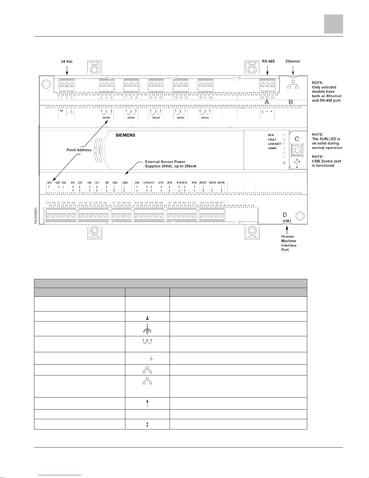
16- and 24-Point Compact Series Diagram
NOTE:
The USB device port is now functional. It requires a computer device driver and
standard computer terminal software, available on Standard Apps).
PXC-16 and PXC-24 Features, Symbols, and Status LEDs.
Terminal Block Connection
Label
Indicates
1
24V
~
Supply voltage, 24 Vac input.
2
System neutral.
3
Functional earth.
4 through 12 (PXC-16)
4 through 18 (PXC-24)
Digital Output relay, Normally Closed (NC), Common (C),
Normally Open (NO).
A (22 through 24)
+ –
RS-485 port.
B
10B/100B Ethernet port.
C
USB Device port. Supports a generic serial interface for an
HMI or Tool connection. Does not support firmware flash
upgrades.
25, 27, 28
Universal Input (+) (UI1 through UI3).
26, 29
–
Signal Common.
30, 31, 33, 34, 36
Universal Input/Output (+) (U4 through U8).
Page 16

Compact Series Product Overview
16- and 24-Point Compact Series Diagram
16
| 100
Siemens Industry, Inc.
Technical Reference Manual
145-172
Building Technologies
Restricted
2018-09-25
PXC-16 and PXC-24 Features, Symbols, and Status LEDs.
Terminal Block Connection
Label
Indicates
37, 39
24 Vdc external sensor power (+) source.
38, 40
–
Signal Common.
41, 43, 44, 46
Universal Input/Output (+) PXC-24 only (U9 through U12).
42, 45
–
Signal Common (PXC-24 only).
47, 49, 50, 52
Super Universal Input/Output (+) PXC-24 only (X13 through
X16).
48, 51
–
Signal Common.
53, 55, 57
Analog Output (+) (PXC-16: AO9 through AO11; PXC-24:
AO17 through AO19).
54, 56
-
Signal Common.
58, 60
Digital Input (+) PXC-16 only (DI12 through DI13).
59
–
Signal Common (PXC-16 only).
D
HMI
Human-Machine Interface port
(RS-232 8-N-1 signal, RJ-45 8 pin connector, service only, will
not dial out.)
Status LEDs
RUN LED
RUN
(green)
ON - Normal steady Green, unit is powered and running. May
briefly flash while processor is booting.
OFF - Error.
● 24 Vac input is not present.
● Power is ON, but the application firmware has not booted.
FAULT LED
FAULT
(red)
(for future use)
Normal Off, not currently implemented. May be Red if
processor does not complete boot.
LOW BATT LED
LOW BATT
(red)
ON -
Error. RAM Battery (AA) is dead, low, missing or shipping
tab is not removed.
OFF - Normal operation.
Ethernet COMM LED
COMM
(yellow)
(BACnet/IP or
Ethernet TCP/IP
(P2) only)
ON - Linked to Ethernet hub.
OFF - No link to Ethernet hub.
RS-485 TX
RS-485 TX
(yellow) (RS-485
only)
Flashing - Transmitting information over the RS-485, RS-485
P2 or BACnet MS/TP ALN or P1 or MS/TP FLN (depending on
how the port is defined).
OFF or ON solid - No device, no connection, or bad
connection.
RS-485 RX
RS-485 RX
(yellow) (RS-485
only)
Flashing - Receiving information over the RS-485, RS-485 P2
or BACnet MS/TP ALN or P1 or MS/TP FLN (depending on
how the port is defined).
OFF or ON solid - No device, no connection, or bad
connection.
PXC-16: DO 14 through DO 16; PXC-24:
DO 20 through DO 24
DO
XX
ON - Relay Energized.
Page 17
Compact Series Product Overview
36-Point Compact Series Product Diagram
17 |
100
Siemens Industry, Inc.
Technical Reference Manual
145-172
Building Technologies
Restricted
2018-09-25
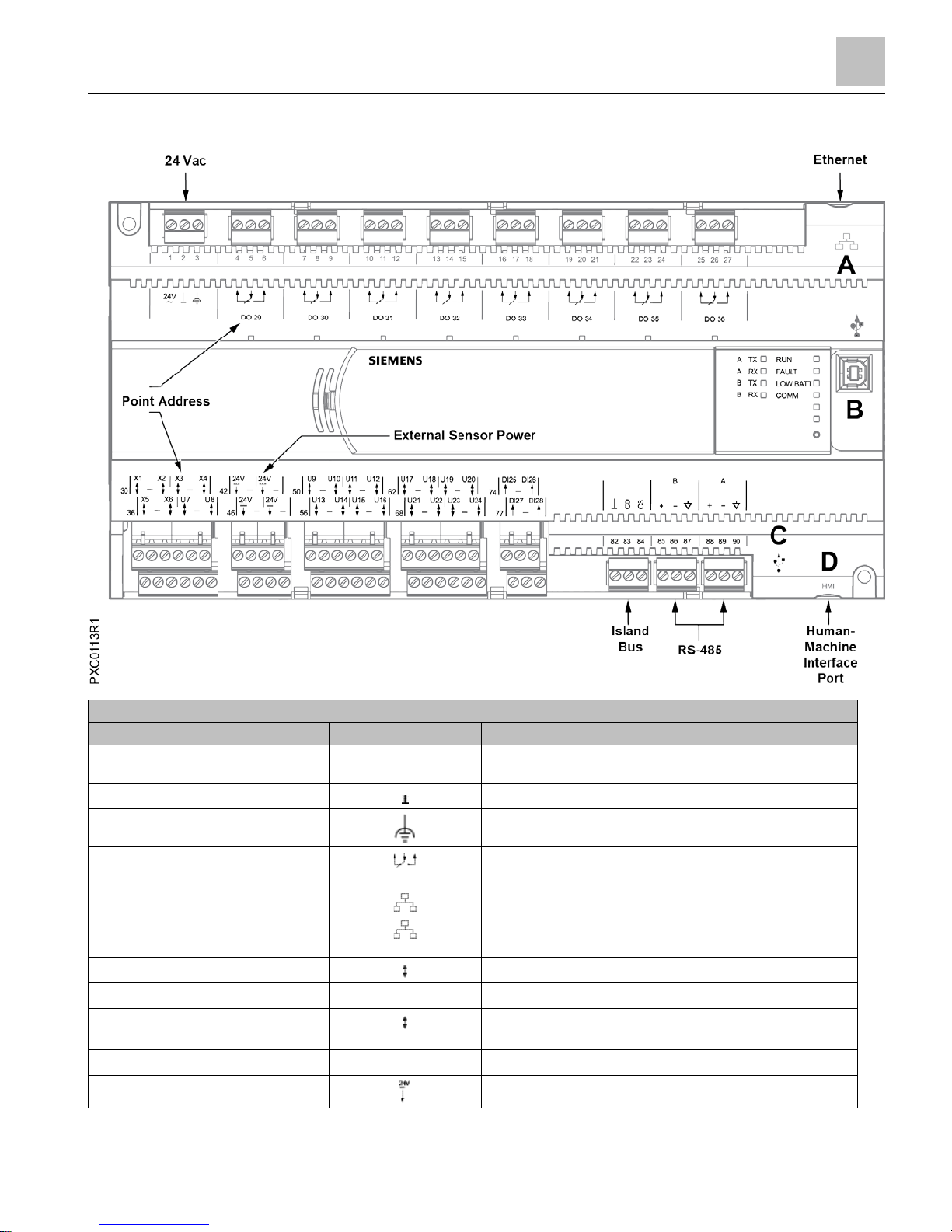
36-Point Compact Series Product Diagram
PXC-36 Features, Symbols, and Status LEDs.
Terminal Block Connection
Label
Indicates
1
24V
~
Supply voltage, 24 Vac input.
2
System neutral.
3
Functional earth.
4 through 27
Digital Output relay, Normally Closed (NC), Common (C), Normally
Open (NO).
A
10B/100B Ethernet port.
B
USB Device port. Supports a generic serial interface for an HMI or
Tool connection. Does not support firmware flash upgrades.
30, 32, 33, 35, 36, 38
Super Universal (+). (X1 through X6)
31, 34, 37
–
Signal Common.
39, 41, 50, 52, 53, 55, 56, 58, 59, 61, 62,
64, 65, 67, 68, 70, 71, 73
Universal Input/Output (+). (U7 through U24)
40, 51, 54, 57, 60, 63, 66, 69, 72
–
Signal Common.
42, 44, 46, 48
24 Vdc external sensor power (+) source.
Page 18

Compact Series Product Overview
36-Point Compact Series Product Diagram
18
| 100
Siemens Industry, Inc.
Technical Reference Manual
145-172
Building Technologies
Restricted
2018-09-25
PXC-36 Features, Symbols, and Status LEDs.
Terminal Block Connection
Label
Indicates
43, 45, 47, 49
–
Signal Common.
74, 76, 77, 79
Digital Input (+) (DI25 through DI28)
75, 78
–
Signal Common
82 through 84
CD CS
Island Bus Communication
85 through 87 and 88 through 90
+ –
RS-485 port.
C
USB Host port
D
HMI
Human-Machine Interface port
(RS-232 8-N-1 signal, RJ-45 8 pin connector, service only, will not
dial out.)
Status LEDs
RUN LED
RUN
(green)
ON - Normal steady Green, unit is powered and running. May
briefly flash while processor is booting.
OFF - Error.
● 24 Vac input is not present.
● Power is ON, but the application firmware has not booted.
FAULT LED
FAULT
(red) (for future
use)
Normal Off, not currently implemented. May be Red if processor
does not complete boot.
LOW BATT LED
LOW BATT
(red)
ON - Error. RAM Battery (AA) is dead, low, missing or shipping tab
is not removed.
OFF - Normal operation.
COMM LED
COMM
(yellow)
(BACnet/IP or Ethernet
TCP/IP (P2) only)
ON - Linked to Ethernet hub.
OFF - No link to Ethernet hub.
RS-485 TX
A TX
(yellow)
Flashing - Transmitting information over RS-485 P1 (FLN 1) or
MS/TP FLN.
B TX
(yellow)
Flashing - Transmitting information over , RS-485 P2 or BACnet
MS/TP ALN or P1 or MS/TP FLN (depending on how the port is
defined)..
A TX or B TX
OFF or ON solid - No device, no connection, or bad connection.
RS-485 RX
A RX
(yellow)
Flashing - Receiving information over RS-485 P1 (FLN 1) or
MS/TP FLN.
B RX
(yellow)
Flashing - Receiving information over , RS-485 P2 or BACnet
MS/TP ALN or P1 or MS/TP FLN (depending on how the port is
defined).
A RX
or
B RX
OFF or ON solid - No device, no connection, or bad connection.
DO 29 through DO 36
DO
XX
ON - Relay Energized.
Page 19
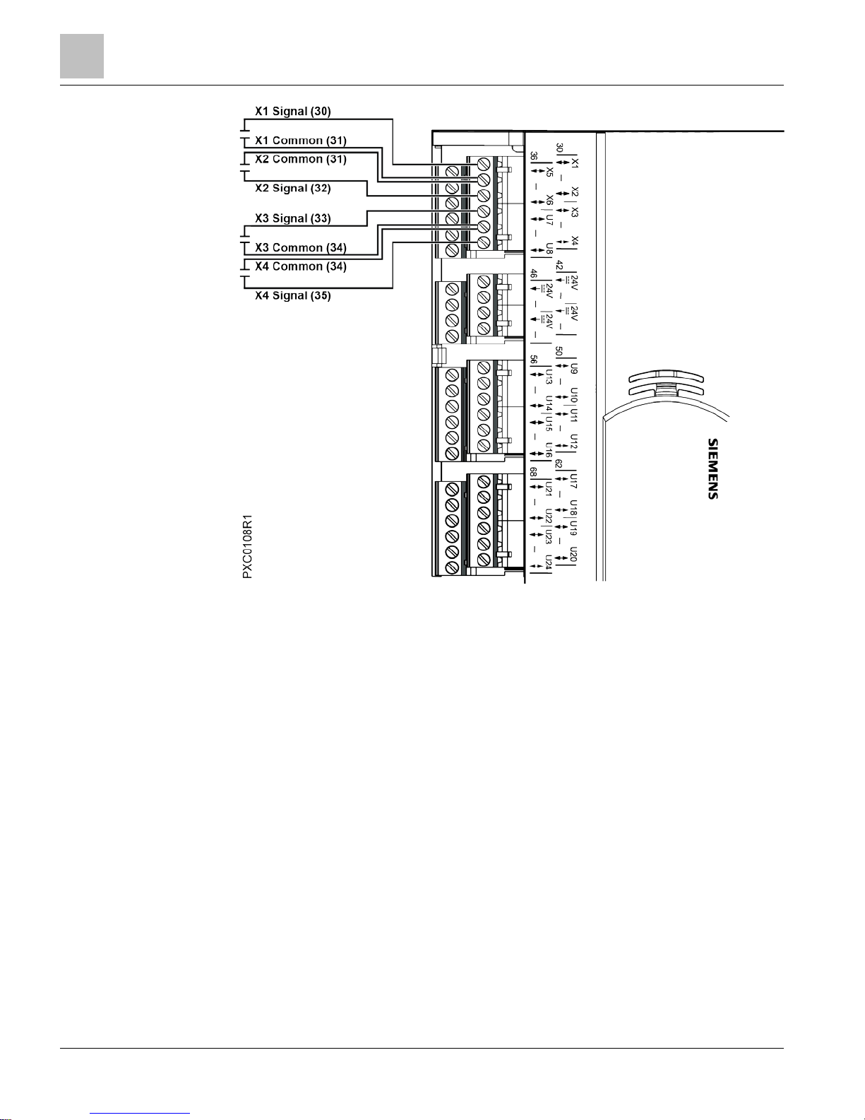
Hardware Features
36-Point Compact Series Product Diagram
19 |
100
Siemens Industry, Inc.
Technical Reference Manual
145-172
Building Technologies
Restricted
2018-09-25
Hardware Features
CAUTION
Adjacent point connections on the PXC Compact Series share a Common
connection. See the Figure,
Common and Sensor Power Connections
.
NOTE:
The common for input and output analog points is floating and is not connected to the
common of the 24 Vac input.
Figure 1: Compact 16/24 Shared Ground Connections.
Page 20
Hardware Features
24 Vdc External Sensor Power Source
20
| 100
Siemens Industry, Inc.
Technical Reference Manual
145-172
Building Technologies
Restricted
2018-09-25
Figure 2: Compact 36 Shared Ground Connections.
24 Vdc External Sensor Power Source
The 24 Vdc Sensor Power source on the PXC Compact should only be used to supply
power to sensors. No accessories of any kind can be powered by this connector.
For powering actuators, use either the 24V ACTUATORS connector on the Service
Box or an external power supply.
Shield Termination
Terminating shield on the enclosure is the preferred method. The "-" termination next
to the 24 Vdc sensor power termination may be used as either a ground for the power
or as a cable shield connection. "-" is not connected to earth ground.
Page 21

Hardware Features
Memory
21 |
100
Siemens Industry, Inc.
Technical Reference Manual
145-172
Building Technologies
Restricted
2018-09-25
Custom Sensor Support
In both P2 Mode (ALN device) and P1 Mode (FLN device), the PXC Compact supports
three custom sensor inputs for the AI points: Johnson Controls Nickel 1000, DIN
Standard Nickel 1000, and Thermistor 10K Type 3. These sensors display as an option
under the Sensor type HMI prompt when entering an AI point at the HMI.
>Sensor type : > 1) I ( Current )
> 2) V ( Voltage )
> 3) P ( Pneumatic )
> 4) T ( Thermistor 100K )
> 5) O ( Thermistor 10K )
> 6) S ( Thermistor 10K Type 3 )
> 7) M ( RTD 1K Platinum 375 )
> 8) R ( RTD 1K Platinum 385 )
> 9) N ( RTD 1K Nickel )
> 10) J ( RTD 1K Nickel JCI )
> 11) D ( RTD 1K Nickel DIN )
> 12) L ( L-Type )
> 13) C ( Custom )
Enter option # or <C> for Cancel> 1-
For the two RTD sensors, use the following updated
Intercept Adjustments
table to
create the value entered at the > Wire resistance adjustment : prompt.
Intercept Adjustments.
RTD Type and temperature
coefficient1
Intercept Formula for
Fahrenheit
2 3
Intercept Formula for Celsius
2 4
(M) RTD 1K Platinum 375 I - (R × ft)/2.117 I - (R × m)/3.8102
(R) RTD 1K Platinum 375 I - (R × ft)/2.171 I - (R × m)/3.9080
(N) RTD 1K Nickel I - (R × ft)/2.459 I - (R × m)/4.427
(J) RTD 1K Nickel JCI I - (R × ft)/2.9667 I - (R × m)5.3400
(D) RTD 1K Nickel DIN I - (R × ft)/3.0589 I - (R × m)5.5060
1)
Intercept Formula uses average temperature coefficient for the sensor connected.
2)
Resistance (R) is from the wire specification or the typical wire resistance table.
3)
I is for the intercept from the field panel Slope/Intercept table and ft is the wire length in feet.
4)
I is for the intercept from the field panel Slope/Intercept table and m is the wire length in meters.
Memory
The APOGEE firmware (program), its point database, PPCL program, trend data, and
other information reside in the field panel memory. Memory consists of two areas:
Flash Read-Only Memory (Flash ROM) and Random Access Memory (RAM).
Page 22

Hardware Features
Memory
22
| 100
Siemens Industry, Inc.
Technical Reference Manual
145-172
Building Technologies
Restricted
2018-09-25
Flash Read-Only Memory (Flash ROM)
Flash Read-Only Memory (Flash ROM) is the non-volatile, permanent memory of the
PXC Compact, which stores the operating system, the APOGEE firmware, and the
language files. A limited amount of secondary storage is provided in Electrically
Erasable Programmable Read-Only Memory (EEPROM) for the field panel address or
name, communication speeds, and other set-up parameters. In the event of a power
surge, a power loss, or failure of the battery backup, the Flash ROM and EEPROM
contents stay intact.
PXC Compact Flash ROM size cannot be upgraded in the field.
Compressed ROM
The PXC Compact has a large amount of high performance RAM. To allow for future
features and to provide high system performance, the APOGEE firmware is stored in
ROM in a compressed state; it is de-compressed into RAM on system power-up. As a
result, the entire onboard RAM is not available for the point database, the PPCL
program, and trend data.
Auto-Restore and Database Backup to Flash
APOGEE Firmware Revision 2.8.4/3.1 and later supports Auto-Restore and Database
Backup to Flash.
● Database Backup to Flash allows the user to manually save a copy of the
database in flash memory of the controller.
● The field panel may be configured to automatically restore the database from flash
memory after a coldstart.
– When auto-restore is enabled, a coldstart does not result in the same downtime
as with earlier revisions of APOGEE Firmware. Because there is no waiting on
a full download from the backup system, the database is restored from flash so
quickly that there is little to no downtime. However, the accumulated trend data
is deleted from memory.
– Database restoration from flash is disabled by default.
– When FLN Mode is selected for the PXC Compact or UEC, database
restoration from flash is automatically enabled.
– When P1 Mode is selected for the PXC Compact, database restoration from
flash is automatically enabled and 128K of memory is reserved for ISB files.
● The field panel may be configured to automatically restore the database from flash
memory after a coldstart.
– When auto-restore is enabled, a coldstart does not result in the same downtime
as with earlier revisions of APOGEE firmware. Because there is no waiting on a
full download from the backup system, the database is restored from flash so
quickly that there is little to no downtime. However, the accumulated trend data
is deleted from memory.
– Database restoration from flash is disabled by default.
For procedures on using Auto-Restore and Database Backup to Flash, see the
APOGEE P2 ALN Field Panel User's Manual (125-3019) or the APOGEE BACnet ALN
Field Panel User's Manual (125-3020).
Page 23

Hardware Features
Compact Series Backup Batteries
23 |
100
Siemens Industry, Inc.
Technical Reference Manual
145-172
Building Technologies
Restricted
2018-09-25
Auto Save
This feature allows the database to be backed up automatically whenever database is
changed, instead of being an operator selected function. It does not provide any
safeguard and or protection against power loss while the process is underway.
However, this feature sends messages to HMI that the auto save operation is in
progress or finished.
The feature may be turned on or off using a prompt similar to the existing Autorestore
prompt. See the APOGEE BACnet ALN Field Panel User's Manual (125-3020) for
more information.
File System Operations
File System Operations provide many features and works on three drives of a field
panel.
The following is a list of supported features:
● List Drives — list the drives on the field panel where A: is the RAM drive, B: is the
USB drive if attached, and
IFD: is the internal Flash Drive.
● Set_drive — identifies the drive that you want to perform other functions on.
● listDirectory — lists the files and folders contained on the selected drive.
● Change_dir — changes the current directory to allow you to view the contents of
subfolders on the drive.
● File_ops — opens up the file control menu which allows you to copy, rename,
delete and move files in the panel. These functions work on the drive that was
selected by the Set_drive function.
● File_ops/Copy_file — allows you to copy files within a drive or to another drive.
● File_ops/Rename_file — allows you to rename a file.
● File_ops/Move_file — allows you to move a file within a drive or to another drive.
● File_ops/Delete_file — allows you to delete a file.
USB Media Support
● Support for USB mass storage devices (Memory sticks or USB hard drives).
● Backup of database, storage for graphics, Web Server upgrades
Random Access Memory (RAM)
Synchronous Dynamic Random Access Memory (SDRAM) is the working memory of
the PXC Compact. When the PXC Compact has booted and is operating normally, the
APOGEE firmware, the PPCL control program, the point database, and trend data
have been transferred from Flash ROM. Information stored in RAM, such as the point
database or PPCL, may be viewed, modified, deleted, activated, or deactivated from
an operator terminal by any high-level authorized user. In the event of a power loss,
the contents of RAM are kept intact by a backup battery.
PXC Compact RAM size cannot be upgraded in the field.
The program length, number of database points, and number of trend entries is limited
only by available memory.
Compact Series Backup Batteries
The PXC Compact Series contains one non-rechargeable AA (LR6) battery and one
non-rechargeable coin cell (BR2032) battery that serve as a power backup in the event
Page 24
Hardware Features
Compact Series Backup Batteries
24
| 100
Siemens Industry, Inc.
Technical Reference Manual
145-172
Building Technologies
Restricted
2018-09-25
of a power failure. The batteries only discharge during a power loss. They do not
recharge.
CAUTION
Only use a 3.6 Volt lithium battery in PXC Compact models with extended
temperature range operation.
Only use a 1.5 Volt alkaline battery in standard PXC Compact models.
• The 3.6 Volt lithium battery is designed to operate at both high and low temperature
extremes, and it provides a long service life in an extended temperature environment.
• The 1.5 Volt alkaline battery is not guaranteed to provide backup protection in
models with extended temperature range operation, even if the controller is operating
in a room-temperature environment.
• If a 3.6 Volt lithium battery is used in standard PXC Compact models, the battery
quickly discharges and provides much less backup protection than a 1.5 Volt alkaline
battery.
AA Battery
CAUTION
Batteries
Failure to change DEAD alkaline battery will eventually result in battery leakage,
causing permanent damage and loss of building control.
Failure to change a DEAD lithium battery will result in loss of trend and database if
not backed up, causing loss of data or building control.
Establish a preventative maintenance schedule based on expected battery usage and
life cycle.
● The AA battery maintains databases and volatile data, such as Trend, in RAM
when power to the controller is off.
● If reserve power in the AA battery is low, the battery status is reported as LOW or
DEAD and the red LOW BATT LED on the field panel is lit. When this occurs,
replace the battery; do not wait until it goes dead.
● Using PPCL and the $BATT point, the PXC Compact can be programmed to signal
an alarm printer and an operator terminal with a battery replacement message.
For more information, see the APOGEE Powers Process Control Language (PPCL)
User's Manual (125-1896).
Using Auto Restore and Database Backup to Flash
● RAM is cleared if the AA battery is dead, disabled, or missing when power to the
field panel is off. In this case, if Auto Restore and Database Backup to Flash have
been enabled, the database reloads in RAM when power returns; however, Trend
data is lost.
● If a power failure lasts longer than the protection offered by the battery, and Auto
Restore and Database Backup to Flash are not enabled, the information stored in
RAM must be either reloaded from an Insight workstation, Datamate Base or
Datamate Advanced, or entered again by an operator.
Page 25
Hardware Features
Compact Series Backup Batteries
25 |
100
Siemens Industry, Inc.
Technical Reference Manual
145-172
Building Technologies
Restricted
2018-09-25
AA Battery
CAUTION
Batteries
Failure to change DEAD alkaline battery will eventually result in battery leakage,
causing permanent damage and loss of building control.
Failure to change a DEAD lithium battery will result in loss of trend and database if
not backed up, causing loss of data or building control.
Establish a preventative maintenance schedule based on expected battery usage and
life cycle.
● The AA battery maintains databases and volatile data, such as Trend, in RAM
when power to the controller is off.
● If reserve power in the AA battery is low, the battery status is reported as LOW or
DEAD and the red LOW BATT LED on the field panel is lit. When this occurs,
replace the battery; do not wait until it goes dead.
● Using PPCL and the $BATT point, the PXC Compact can be programmed to signal
an alarm printer and an operator terminal with a battery replacement message.
Monitoring the State of the AA Battery
● The resident AI point $BATT monitors the state of the AA battery.
– Status is reported as ALIVE for a value of 100.
– Status is reported as DEAD for a value of 0.
● Access BATT from the HMI or PPCL using one of the following:
– “!Field panel
<node>
:BATT” for RS-485 P2 or BACnet MS/TP ALN
–
“!<Node Name>
:BATT” for BACnet/IP or Ethernet TCP/IP (P2) ALN
– “*:BATT” where wildcard is permitted.
– The short name $BATT in PPCL.
For more information, see the APOGEE Powers Process Control Language (PPCL)
User's Manual (125-1896).
Using Auto Restore and Database Backup to Flash
● RAM is cleared if the AA battery is dead, disabled, or missing when power to the
field panel is off. In this case, if Auto Restore and Database Backup to Flash have
been enabled, the database reloads in RAM when power returns; however, Trend
data is lost.
● If a power failure lasts longer than the protection offered by the battery, and Auto
Restore and Database Backup to Flash are not enabled, the information stored in
RAM must be either reloaded from an Insight workstation, Datamate Base or
Datamate Advanced, or entered again by an operator.
NOTE:
The information stored in RAM may also be reloaded using Commissioning Tool (CT).
● If Auto Restore and Database Backup to Flash have been enabled, the AA battery
may be removed from the PXC Compact if there is not a requirement to maintain
volatile data, such as Trend, over a power cycle.
Page 26
Hardware Features
Compact Series Backup Batteries
26
| 100
Siemens Industry, Inc.
Technical Reference Manual
145-172
Building Technologies
Restricted
2018-09-25
Coin Cell Battery
The coin cell battery is present on all PXC-36 Compact Series and on Version 2 or
later of PXC-16 and PXC-24. The hardware version is indicated in the Product Number
as follows:
● The number after
PXC16
or
PXC-24
indicates the hardware version. For example,
PXC24
.2-PE.A is Version 2.
● No number after
PXC16
or
PXC-24
is Version 1 hardware. For example, PXC24-
PE.A is Version 1.
CAUTION
Batteries
Failure to change a DEAD lithium coin cell battery will result in loss of current timedate, which may cause loss of data or building control.
Establish a preventative maintenance schedule based on expected battery usage and
life cycle.
● The coin cell battery maintains the current time-date in the Real Time Clock (RTC)
when power to the field panel is off.
● There is no physical status on the field panel for a dead coin cell battery.
● If the coin cell battery is dead or missing when power is off, then RTC time-date is
reset as follows:
– If the field panel resides on an ALN with an Insight workstation, the Insight
workstation sets the time-date when the field panel returns to the network.
– If the field panel resides on an ALN without an Insight workstation, the time-
date is synchronized with the network time during the next automatic daily time
update.
● When the PXC Compact is operating in P1 mode, if the coin cell battery is dead or
missing when power is off, RTC time-date is reset to the factory default. RTC timedate and must be set manually or by PPCL to ensure time-date based applications
operate as expected.
For more information on time synchronization, see the APOGEE P2 ALN Field Panel
User's Manual (125-3019) or the APOGEE BACnet ALN Field Panel User's Manual
(125-3020) (125-3019 or 125-3020).
Page 27
Hardware Features
Compact Series Backup Batteries
27 |
100
Siemens Industry, Inc.
Technical Reference Manual
145-172
Building Technologies
Restricted
2018-09-25
Coin Cell Battery
The coin cell battery is present on all PXC-36 Compact Series and on Version 2 or
later of PXC-16 and PXC-24. The hardware version is indicated in the Product Number
as follows:
● The number after
PXC16
or
PXC-24
indicates the hardware version. For example,
PXC24
.2-PE.A is Version 2.
● No number after
PXC16
or
PXC-24
is Version 1 hardware. For example, PXC24-
PE.A is Version 1.
CAUTION
Batteries
Failure to change a DEAD lithium coin cell battery will result in loss of current timedate, which may cause loss of data or building control.
Establish a preventative maintenance schedule based on expected battery usage and
life cycle.
● The coin cell battery maintains the current time-date in the Real Time Clock (RTC)
when power to the field panel is off.
● There is no physical status on the field panel for a dead coin cell battery.
● If the coin cell battery is dead or missing when power is off, then RTC time-date is
reset as follows:
– If the field panel resides on an ALN with an Insight workstation, the Insight
workstation sets the time-date when the field panel returns to the network.
– If the field panel resides on an ALN without an Insight workstation, the time-
date is synchronized with the network time during the next automatic daily time
update.
● When the PXC Compact is operating in P1 mode, if the coin cell battery is dead or
missing when power is off, RTC time-date is reset to the factory default. RTC timedate and must be set manually or by PPCL to ensure time-date based applications
operate as expected.
For more information on time synchronization, see the APOGEE P2 ALN Field Panel
User's Manual (125-3019) or the APOGEE BACnet ALN Field Panel User's Manual
(125-3020) (125-3019 or 125-3020).
Monitoring the State of the Coin Cell Battery
● Resident AI point BATT2 monitors the state of the RTC oscillator when power is
applied to the field panel either during a coldstart or a warmstart.
– If the oscillator is stopped, BATT2 is set to value 0.
– If the RTC oscillator is valid, BATT2 is set to value 100.
– Status is reported as DEAD for a value of 0.
– Status is reported as OK for a value of 100.
NOTE:
The value of
BATT2
is also set to
100
by a coldstart command. Since the controller is
powered and the RTC oscillator does not stop, the value of BATT2 is valid and a
time-date reset will not occur.
Page 28

Hardware Features
Compact Series Specifications
28
| 100
Siemens Industry, Inc.
Technical Reference Manual
145-172
Building Technologies
Restricted
2018-09-25
● Access BATT2 from the HMI or PPCL using one of the following:
– “!Field panel
<node>
:BATT2” for RS-485 P2 or BACnet MS/TP ALN
–
“!<Node Name>
:BATT2” for BACnet/IP or Ethernet TCP/IP (P2) ALN
– “*:BATT2” where wildcard is permitted.
● In PPCL, BATT2 cannot be automatically accessed using the short name $BATT2;
instead, use the full name. That is,
“!Field panel
<node>
:BATT2” for RS-485 P2 or
BACnet MS/TP ALN or
“!<Node Name>
:BATT2” for BACnet/IP or Ethernet TCP/IP
(P2) ALN.
Memory Size and Typical Battery Backup Time
Memory Size and Typical Battery Backup Time.
Compact Model
RAM Flash ROM
Total Memory
Typical Battery Backup
RAM and Real Time Clock Data
1
PXC-16 and PXC-24 16 MB 8 MB 24 MB
Non-rooftop models: 180 days
(accumulated)
Rooftop models: 330 days
(accumulated)
PXC-16 and PXC-24
“F” and “F32”
32 MB 8 MB 40 MB
Non-rooftop models (accumulated):
110 days (accumulated)
Rooftop models: (accumulated):
200 days (accumulated)
PXC-36 64 MB 16 MB 80 MB 60 days (accumulated)
1)
Installing a coin cell battery provides up to 10 years backup power of the Real Time Clock for nonrooftop applications, and 18 months backup power for rooftop applications. These are typical
accumulated times while power is off.
Compact Series Specifications
Dimensions (L × W × D)
PXC-16 and PXC-24
10.7" × 5.9" × 2.45"
(272 mm × 150 mm × 62 mm)
PXC-36
11.5" × 5.9" × 3.0"
(293 mm × 150 mm × 77 mm)
DIN rail (EN 60715 TH 35-7.5, steel)
1.38" × 0.30" × 0.04"
(35 mm × 7.5 mm × 1 mm)
Page 29

Hardware Features
Compact Series Specifications
29 |
100
Siemens Industry, Inc.
Technical Reference Manual
145-172
Building Technologies
Restricted
2018-09-25
Processor, Battery, and Memory
Processor and Clock Speed PXC-16 and PXC-24: Freescale MPC852T, 100 MHz
PXC-36: Freescale MPC885, 133 MHz
Memory PXC-16 and PXC-24: 24 MB (16 MB SDRAM, 8 MB Flash ROM)
PXC-16/24 “F” and “F32”: 40 MB (32 MB SDRAM, 8 MB Flash ROM)
PXC-36: 80 MB (64 MB SDRAM, 16 MB Flash ROM)
NOTE:
See the Configuration and Sizing Guidelines document for supported memory size.
New PXC models will now support high speed 480 Mbps communication (PXC-36 only).
Serial EEPROM 4 KB
Battery backup of Synchronous Dynamic
(SD) RAM (field replaceable)
Non-
rooftop Models
AA (LR6) 1.5 Volt Alkaline (non-rechargeable)
PXC-16 and PXC-24: 180 days (accumulated)
PXC-16 and PXC-24 F and F32: 110 days (accumulated)
PXC-36: 60 days (accumulated)
Rooftop (Extended
Temperature) Models
AA (LR6) 3.6 Volt Lithium (non-rechargeable): 90 days (accumulated)
32MB SDRAM Rooftop (lithium): 200 days
16MB SDRAM Rooftop (lithium): 330 days
Battery backup of Real Time Clock
Non-
rooftop Models
10 years (32°F to 122°F (0°C to 50°C))
Coin cell (BR2032) 3 Volt lithium
Rooftop (Extended Temperature) Models
18 months (-40°F to 158°F (-40°C to 70°C))
Coin cell (BR2032) 3 Volt lithium
These are typical accumulated times while power is off.
Communication
BACnet/IP or Ethernet TCP/IP (P2)
Automation Level Network (ALN) or
BACnet/IP or Ethernet TCP/IP (P2) Floor
Level Network (FLN)
10Base-T or 100Base-TX compliant
10 Mbps or 100 Mbps (autoswitching) over Ethernet cable, RJ-45 jack, shielded, 328 ft (100
m) max. from the field panel to the nearest active hub, router, or signal repeater. Up to 100
nodes per BACnet/IP or Ethernet TCP/IP (P2) ALN or FLN.
10Base-
T Connection Requirements
UTP/STP Category 3 or 5 or better cable
100Base-TX Connection Require
ments
UTP/STP Category 5 or better cable
Supports CSMA/CD protocol, compatible with IEEE 802.xx compliant devices.
PXC-36 supports Auto-MDIX
BACnet MS/TP Automation Level Network
(ALN)
9600 bps to 115.2 Kbps, up to 10 nodes per MS/TP ALN
RS-485 Automation Level Network (ALN)
1200 bps to 115.2 Kbps over 24-gauge, low capacitance shielded twisted pair cable, 4000 ft
(1220 m) max. @ 57.6 Kbps or less, 3280 ft (1 km) max. @ 115.2 Kbps. Up to 100 nodes per
RS-485 ALN.
Human-Machine Interface (HMI)
Three wire, full-duplex, asynchronous serial RS-232 compliant, 1200 bps to 115.2 Kbps, 8-N-
1, no hardware flow control (Xon/Xoff supported). RJ-45 jack, 50 ft (16 m) max. cable length.
Supports dial-in modem.
Factory-
set HMI Communication Speed
PXC-16 and PXC-24: 9600 bps
PXC-36: 115.2 Kbps
Page 30

Hardware Features
Compact Series Specifications
30
| 100
Siemens Industry, Inc.
Technical Reference Manual
145-172
Building Technologies
Restricted
2018-09-25
Communication
USB Device port (for non-smoke control
applications only)
Prior to June 2013
USB 1.1 (12 Mbps) and 2.0 (480 Mbps), Type B female connector.
Self-powered, does not use or supply USB power.
USB 1.0 (1.5 Mbps) and 1.1 (12 Mbps).
NOTE:
See the
Configuration and Sizing Guidelines
documentation for supported speeds per
controller model.
USB Host port (for ancillary smoke control
applications only).
Prior to June 2013
USB 1.0 (1.5 Mbps), 1.1 (12 Mbps), and 2.0 (480 Mbps), Type A female connector.
USB unit loads (5V, 500 mA).
USB 1.0 (1.5 Mbps) and 1.1 (12 Mbps), Type A female connector.
NOTE:
See the
Configuration and Sizing Guidelines
documentation for supported speeds per
controller model..
FLN Support available on selected models, license may be required
RS-485 P1 Field Level Network (FLN)
4800 bps to 38.4 Kbps over 24-gauge, low capacitance shielded twisted pair cable, 4000 ft
(1220 m) max. @ 38.4 Kbps.
PXC-16 and PXC-24: Up to 32 FLN devices supported.
PXC-36: For full-load FLN devices, up to 32 devices per FLN port.
For 1/8-load FLN devices, up to 96 devices per field panel.
BACnet MS/TP Field Level Network (FLN) 9600 bps to 115.2 Kbps
PXC-16 and PXC-24: Up to 32 FLN devices supported.
PXC-36: For full-load FLN devices, up to 32 devices per FLN port.
For 1/8-load FLN devices, up to 96 devices per field panel.
Electrical
Power Requirements 24 Vac ±20% input @ 50/60 Hz
Power Consumption (Maximum) PXC-16: 18 VA @ 24 Vac
PXC-24: 20 VA @ 24 Vac
PXC-36: 35 VA @ 24 Vac
A/D Resolution (analog in) 16 bits
D/A Resolution (analog out) 10 bits
AC Power and Digital Outputs NEC Class 1 Power Limited
Communication and all other I/O NEC Class 2
Digital Input
Dedicated Points
PXC-16:
Points 12-
13
PXC-36:
Points 25-
28
Contact Closure Sensing
Dry Contact/Potential Free inputs only
Does not support counter inputs
Open Circuit Voltage: 24 Vdc
Short Circuit Current: 10 mA
Configurable Points
PXC-16:
Points 1-
8
PXC
-
24:
Points 1-
16
PXC
-
36:
Points 1-
24
Contact Closure Sensing
Dry Contact/Potential Free inputs only
Digital Input (10 ms settling time)
Supports counter inputs up to 20 Hz, minimum
pulse duration 20 ms (open or closed)
Page 31

Hardware Features
Compact Series Specifications
31 |
100
Siemens Industry, Inc.
Technical Reference Manual
145-172
Building Technologies
Restricted
2018-09-25
Electrical
Digital Output
Dedicated Points
PXC
-
16:
Points 14-
16
PXC
-
24:
Points 20-
24
PXC
-
36:
Points 29-
36
Class 1 Relay
Form-C (NO and NC contacts)
125 Vac, 4A
250 Vac, 2A
Configurable Points
using an external relay
PXC-24:
Points 13-
16
PXC-36:
Points 1-
6
0 to 24 Vdc, 22 mA max.
Analog Output
Dedicated Points
PXC-16:
Points 9-
11
PXC-24:
Points 17-
19
0 to 10 Vdc @ 1 mA max.
Resolution: 11 mV
Initial Accuracy: ±2% of full range (32°F to 122°F
(0°C to 50°C) ambient)
Analog Output
Configurable Points, 0 to 10 Vdc
PXC-16:
Points 4-
8
PXC
-
24:
Points 4-
16
PXC-36:
Points 1-
24
0 to 10 Vdc @ 1 mA max.
Resolution: 11 mV
Initial Accuracy: ±2% of full range (32°F to 122°F
(0°C to 50°C) ambient)
Configurable Points, 0 to 20 mA
PXC-24:
Points 13-
16
PXC-36:
Points 1-
6
0 to 20 mA @ 650 Ω max.
Resolution: 22 µA
Initial Accuracy: ±2% of full range (32°F to 122°F
(0°C to 50°C) ambient)
Analog Input
Configurable Points
PXC-16:
Points 1-
8
PXC
-
24:
Points 1-
16
PXC
-
36:
Points 1-
24
Voltage (0-10 Vdc) Resolution: 2.2 mV
Current (4-20 mA) Resolution: 4.4 µA
1K Ni RTD @ 32°F (Siemens, JCI, DIN Ni 1K) Resolution: 0.05 C
1K Pt RTD (375 or 385 alpha) @ 32°F Resolution: 0.08 C (375), 0.13 C (385)
10K NTC Type 2 or Type 3 Thermistor Resolution: 0.02 C to 0.10 C
100K NTC Type 2 Thermistor Resolution: 0.14 C to 0.02 C
Page 32

Hardware Features
Compact Series Specifications
32
| 100
Siemens Industry, Inc.
Technical Reference Manual
145-172
Building Technologies
Restricted
2018-09-25
Operating Environment
Ambient operating environment
Operate in a dry location, which is protected from exposure to salt spray or other corrosive
elements. Exposure to flammable or explosive vapors must be prevented.
Ambient operating temperature 32°F to 122°F (0°C to 50°C)
Ambient operating temperature
with rooftop
(extended temperature) option
-40°F to 158°F (-40°C to 70°C)
Relative Humidity PXC-16 and PXC-24: 5 to 95% rh non-condensing
PXC-36: 5 to 95% rh non-condensing
Shipping and storage environment PXC-16 and PXC-24:
-40°F to 185°F (-40°C to 85°C)
PXC-36:
-13°F to 158°F (-25°C to 70°C)
Mounting Surface PXC-16 and PXC-24:
Direct equipment mount, building wall, or structural member
PXC-36:
Building wall or a secure structure
CE Compliance
Must be installed inside a metal enclosure rated at IP20 minimum
Smoke Control Applications
Requires installation inside a PX series enclosure
Outdoor Applications
Requires installation inside a NEMA-4 rated enclosure, or a similarly-protected
environment
Vibration Compliance to IEC 60721, Class 2M2 and 3M2
Protection to EN60529 IP 20
Agency Listings
UL
UL864 UUKL Smoke Control Equipment (except UEC and rooftop models)
UL864 UUKL7 Smoke Control Equipment (except UEC and rooftop models)
CAN/ULC-S527-M8 (except rooftop models)
UL916 PAZX (all models)
UL916 PAZX7 (all models)
Agency Compliance
FCC Compliance CFR47 Part 15, Subpart B, Class B
Australian EMC Framework
European EMC Directive (CE)
European Low Voltage Directive (LVD)
RoHS Compliant
OSHPD Seismic Certification
Product meets OSHPD Special Seismic Preapproval certification (OSH-0217-10) under California
Building Code 2010 (CBC2010) and International Building Code 2009 (IBC2009) when installed
within the following Siemens enclosure part numbers: PXA-ENC18, PXA-ENC19, or PXA-ENC34.
BTL BACnet Testing Laboratories (BTL) Certified, Firmware Revision 3.0 and later
Page 33

Hardware Features
Communication Connections
33 |
100
Siemens Industry, Inc.
Technical Reference Manual
145-172
Building Technologies
Restricted
2018-09-25
Electrical Disturbance Testing
Dips and Interrupts per EN 61000-4-11
Electrical Fast Transients (EFT)
per EN 61000-4-4
1 kV signal, 2 kV AC power
Electrical Surge Immunity
per EN 61000-4-5
AC power: 2 kV common mode, 1 kV differential mode
Electrostatic Discharge (ESD) PXC-16 and PXC-24: per EN 61000-4-2, 6 kV contact, 8 kV air discharge
PXC-36: per EN 61000-4-2, 4 kV contact, 8 kV air discharge
RF Conducted Immunity per EN 61000-4-6 @ 10V
RF Radiated Immunity per EN 61000-4-3 @ 10V/m
Sensor Limits
Sensor Type
Signal Range
Fail Low
Return Low
Fail High
Return High
Voltage Input 0 to 11 Vdc -1.0 Vdc -0.5 Vdc +12.0 Vdc +11.5 Vdc
Current Input 4 to 20 mA 3.68 mA 3.92 mA 21.5 mA 21.0 mA
10KΩ Thermistor
-58°F to +302°F
(-50°C to +150°C)
-65°F -60°F +320°F +311°F
100KΩ Thermistor
-58°F to +302°F
(-50°C to +150°C)
-65°F -60°F +320°F +311°F
Pt 1KΩ RTD
(TC 375)
-40°F to +248°F
(-40°C to +120°C)
-55°F -60°F +266°F +257°F
Pt 1KΩ RTD
(TC 385)
-58°F to +752°F
(-50°C to +400°C)
-75°F -57°F +770°F +761°F
Ni 1KΩ RTD
-58°F to +302°F
(-50°C to +150°C)
-65°F -60°F +320°F +311°F
1000 Ω Nickel DIN
Standard
-58°F to +302°F
(-50°C to +150°C)
-65°F -60°F +320°F +311°F
JCI Nickel 1000K
-40°F to 180°F
(-40°C to 82°C)
-55°F -50°F +240°F +220°F
10K Termistor Type 3
-58°F to +302°F
(-50°C to +150°C)
-65°F -60°F +320°F +311°F
Communication Connections
The PXC Compact Series provides the following communication connections:
● HMI and Tool ports
● 10B/100B Ethernet port
● RS-485 port
● USB Host Port
● TX-I/O Island Bus (PXC-36 only)
PXC Compact hardware that contains both a 10B/100B Ethernet port and an RS-485
port can be configured through the HMI to reside on any of the following:
● BACnet/IP or Ethernet TCP/IP (P2) ALN
● RS-485 P2 or BACnet MS/TP ALN
Page 34

Hardware Features
Communication Connections
34
| 100
Siemens Industry, Inc.
Technical Reference Manual
145-172
Building Technologies
Restricted
2018-09-25
NOTE:
Changing the ALN type coldstarts the field panel.
NOTE:
In BACnet/IP or Ethernet TCP/IP (P2) ALN mode, RS-485 parameters are displayed
and may be entered as a selection. However, when in RS-485 ALN mode, BACnet/IP
or Ethernet TCP/IP (P2) ALN parameters are not an available selection.
HMI and Tool Ports
● The HMI port provides a connection to a laptop computer for local operation and
engineering.
● The USB Device port supports a generic serial interface for an HMI or Tool
connection.
Human-Machine Interface (HMI)/Tool Port
The Human-Machine Interface (HMI)/Tool port provides RS-232 compliant
communications through a quick-connect RJ-45 jack. The HMI port supports the
following functionality:
● Connecting a machine interface device, such as an operator terminal or a text-
based operator terminal, to the PXC Compact.
● Executing firmware flash upgrades.
● 1200 bps to 115.2 Kbps communication is supported.
NOTE:
The communication speed of the port must match the communication speed of the
device connected to it.
USB Device Port
The USB Device port supports a generic serial interface for an HMI or Tool device. The
USB Device port does not support firmware flash upgrades.
A driver must be loaded on the PC in order to communicate with the USB Device port.
The driver is located in StdApps\Apogee\Firmware\USB Drivers.
Page 35

Hardware Features
Communication Connections
35 |
100
Siemens Industry, Inc.
Technical Reference Manual
145-172
Building Technologies
Restricted
2018-09-25
Pin-Out Diagrams for HMI Connectors
The HMI connector supports either a RJ-12 (6-pin) jack or a RJ-45 (8-pin) jack.
CAUTION
Do not use RJ-11 plugs without voids at pins 1 and 8.
RJ-11 plugs without voids will permanently damage the outer pins of the HMI port,
and the HMI port will no longer be able to power HMI terminals or connect to user
interfaces.
Replacement plugs with voids are available and may be installed using an RJ-45
(Ethernet) crimp tool.
NOTE:
RJ-11 HMI accessories can be connected to the middle six pins of the HMI RJ-45
port.
Figure 3: RJ-11 Plug with Voids at Pins 1 and 8.
Figure 4: P/N 540-143.
Standard RJ-11 (6-pin) Tool Socket for RS-232 Devices.
Pin Description
Pin Description
1 Not connected 4 Not connected
2 Ground 5 RxD
3 24 Vdc 6 TxD
Page 36

Hardware Features
Communication Connections
36
| 100
Siemens Industry, Inc.
Technical Reference Manual
145-172
Building Technologies
Restricted
2018-09-25
Standard RJ-45 (8-pin) Tool Socket for RS-232 Devices.
Pin Description
Pin Description
1 Not connected 5 Not connected
2 Not connected 6 RxD
3 Ground 7 TxD
4 24 Vdc 8 Not connected
10B/100B Ethernet Port
The 10B/100B Ethernet port provides a path for commands and information
transmitted between field panels inside a firewall. This port provides both full- and halfduplex 10Base-T or 100Base-TX compliant communications over a BACnet/IP or
Ethernet TCP/IP (P2) Automation Level Network (ALN). The highest possible
communication speed is automatically detected and selected.
RS-485 Port
The RS-485 port provides a path for commands and information transmitted between
field panels. This port provides communications over a RS-485 P2 or BACnet MS/TP
Automation Level Network (ALN) or P1 or MS/TP Field Level Network (FLN). The
communication speed is set during startup.
The RS-485 port provides half-duplex, asynchronous serial RS-485 communications
over shielded twisted pair cable. The RS-485 connector is labeled + – to indicate the
positive and negative connections; is a reference pin.
● The PXC-36 provides two RS-485 ports, which are labeled “A” and “B”.
● All PXC-36 models and the PXC-16 and PXC-24 "F" models support P1 or MS/TP
FLN devices on the RS-485 port.
● BACnet MS/TP routed FLN is supported for Programmable TECs (PTECs), Unitary
Equipment Controllers (UECs), and third-party BACnet devices.
– FIN Builder supports MS/TP routed FLNs and IP FLNs.
– PPCL and Point Editing are currently not available on routed FLNs.
● When the PXC Compact Series is operating in P1 Mode (PXC-16 and PXC-24
only), the RS-485 port connects the PXC Compact to a P1 FLN where it emulates
a TEC.
● When communicating on an RS-485 ALN, the Virtual AEM may be used to
communicate with a P2 Ethernet network.
Page 37

Hardware Features
Communication Connections
37 |
100
Siemens Industry, Inc.
Technical Reference Manual
145-172
Building Technologies
Restricted
2018-09-25
PXC-36 RS-485 A and B Ports
The following table outlines the configuration options for the PXC-36 RS-485 “A“ and
“B“ ports.
ALN Protocol
RS-485 A Port Options (FLN 1)
RS-485 B Port Options (FLN 2)
BACnet/IP MS/TP FLN Not available
P1 FLN P1 FLN1
BACnet MS/TP P1 FLN or MS/TP FLN Configured for MS/TP ALN
Ethernet TCP/IP P1 FLN P1 FLN1
RS-485 P1 FLN Configured for P2 ALN
1)
When two FLN ports are available, both FLN protocols cannot be used on the same field panel.
FLN Support
All PXC-36 models and PXC-16 and PXC-24 "F" models provide a hardware
connection for Field Level Network (FLN) devices, including:
● Siemens Industry FLN.
● Wireless P1 FLN.
An additional license is required to enable some of these FLN connections.
Siemens Industry FLN
The Siemens Industry Field Level Network (FLN) can consist of devices that
communicate over an RS-485 connection using either MS/TP or Protocol 1 (P1).
● BACnet/IP ALN networks support application-specific control devices that
communicate using MS/TP or P1.
● Ethernet TCP/IP and RS-485 ALN networks only support application-specific
control devices that communicate using P1.
ALN Protocol
FLN Protocol
Supported
Firmware Revision
Number of FLN Devices
Drop Number Range
BACnet/IP
MS/TP or P1
(RS-485)
PXC-16, and PXC-24: 3.1 and later
PXC-36: 3.2 and later
PXC-16 and PXC-24: Up to
32 FLN devices.
PXC-36: Up to 96 devices
per field panel.
1
0 to 254
Ethernet TCP/IP or
RS-485
P1 (RS-485) 2.8.5 and later
PXC-16 and PXC-24: Up to
32 FLN devices.
PXC-36: Up to 96 devices
per field panel.
1
0 to 254
2.8.4 and earlier (PXC-16 and
PXC-24 only)
Up to 32 FLN devices. 0 to 31 if networked
0 to 99 if stand-alone
1)
The devices may be grouped in any combination on the FLN ports as long as the total number of FLN devices on the field
panel does not exceed 96.
Wireless P1 FLN
Wireless P1 FLN replaces the traditional FLN cabling with wireless communication
links that form a wireless mesh network. The Wireless FLN is enabled through the PXC
Compact HMI.
Page 38

Hardware Features
Communication Connections
38
| 100
Siemens Industry, Inc.
Technical Reference Manual
145-172
Building Technologies
Restricted
2018-09-25
NOTE:
A P1 FLN license must be installed in order to use Wireless FLN.
NOTE:
The PXC Compact on P1 is not supported on the Wireless FLN.
The following additional hardware is required to implement the Wireless P1 FLN with
the PXC Compact Series:
● Field Level Network Transceiver (FLNX)
● Field Panel Transceiver (FPX)
See the section Minimum Firmware Revision Required [➙ 10] for information on the
firmware revision required to implement Wireless P1 FLN.
PXC Compact on P1
The PXC-16 and the PXC-24 may be configured to reside on the P1 Field Level
Network (FLN). When configured for the FLN, the PXC Compact functions as a
programmable FLN device, which accepts custom applications.
PXC Compact on P1
The PXC-16 and the PXC-24 may be configured to reside on the P1 Field Level
Network (FLN). When configured for the FLN, the PXC Compact functions as a
programmable FLN device, which accepts custom applications.
See the section
Minimum Firmware Revision Required
for information on the firmware
revision required to implement operation on the P1 FLN.
Virtual AEM
Without additional hardware, the Virtual AEM connects an RS-485 APOGEE
Automation Level Network (ALN) or individual RS-485 field panels to a P2 Ethernet
network.
● An additional license is required.
Virtual AEM
● The Virtual AEM is fully configurable from the HMI. Configuration is the same as for
hardware AEM.
● Even though hardware is not connected to the HMI port, the settings for the
HMI/Modem are used to select Alarm Printing/Report Printing, BLN Descriptor, and
BLN NAME.
– The Alarm Printing and Report Printing settings have no effect on AEM
operations (Virtual or hardware).
– Baud rate settings have no effect on the data transmission.
Page 39

Hardware Features
HOA (Hand-Off-Auto) Upgrade Kits
39 |
100
Siemens Industry, Inc.
Technical Reference Manual
145-172
Building Technologies
Restricted
2018-09-25
USB Host Port
The USB host port supports a USB printer and connection to a modem through a USBto-RS-232 adapter. A USB hub may be used to support both a printer and modem on
the USB host port.
● On a BACnet/IP ALN, the USB Host port provides support for service modems and
line printers.
● On an Ethernet TCP/IP or RS-485 ALN, the USB Host port provides support for
dial-up or service modems and line printers.
TX-I/O Island Bus
The PXC-36 offers the flexibility of expanding the total point count through a selfforming island bus. With the addition of TX-I/O modules and a TX-I/O Power Supply,
up to 32 points (or four TX-I/O modules) can be supported.
An additional license may be required to enable the Island Bus.
HOA (Hand-Off-Auto) Upgrade Kits
HOA Upgrade Kits are available for PXC Compact Series field panels. HOA Upgrade
Kits are not compatible with Unitary Equipment Controllers (UEC 16 or UEC 24). The
upgrade kits replace PXC Compact covers with new covers equipped with manual
override switches and LEDs for visual feedback at the field panel.
Users can override the default switch assignment or customize the switches to their
desired configuration.
● The HOA module can be used to override outputs and monitor inputs.
● The HOA mapping and definition of a logical point in the database can be done in
any order.
● The HOA is hot-swappable. The module can be installed without powering down
the controller and interrupting facility operations.
● The HOA module can also be remote mounted on the inside or outside of an
enclosure door, using an optional accessory sold separately.
The firmware provides a default HOA switch assignment based on the type of the host
field panel. There are new menus available that allow for the identification of what HOA
module is connected and communicating, along with the ability to view and customize
the HOA switch mapping.
Page 40

Hardware Features
HOA (Hand-Off-Auto) Upgrade Kits
40
| 100
Siemens Industry, Inc.
Technical Reference Manual
145-172
Building Technologies
Restricted
2018-09-25
HOA Specifications
Electrical
Power Consumption
Baud rate
5 V/60 mA
(from host controller)
38400
Dimensions
(L x W x D)
5.65 in. × 1.8 in. × 0.68 in.
(14.4 cm × 4.6 cm × 1.7 cm)
Weight
8 Switch
16 Switch
0.12 lb
0.14 lb
Operating Environment
Ambient Operating Temperature
Ambient Operating Temperature for rooftop (extended
temperature model)
Shipping and Storage
23°F to 122°F (-5°C to 50°C)
-40°F to 158°F (-40°C to 70°C)
-13°F to 167°F(-25°C to 70°C)
Agency Listings
UL Listing
cUL Listed
FCC Compliance
WEEE
RoHS
UL864 UUKL (except rooftop model)
UL864 UUKL7 (except rooftop model)
CAN/ULC-S527-M8 (except rooftop model)
UL 916 PAZX (all models)
Canadian Standards C22.2 No. 205-M1983, PAZX7
47 CFR Part 15
Hardware Features
HOA switches enable points to be manually placed into HAND, ON/OFF, or AUTO
control. Analog outputs can also be placed into AUTO and ten manual control
positions.
Serial communication is made by either direct connect or through the use of a serial
HMI cable.
Default Mapping
For each type of PXC Compact (16, 24 and 36) that supports HOA and each HOA unit
(8, 16 rooftop or 16 non-rooftop UL 864), there is a default mapping between each
button and physical point.
The default mapping provides Plug-and-Play functionality. Upon connection of the
HOA Upgrade Kit to the host field panel, the HOA device is recognized and its
switches are automatically assigned to the controllers fixed digital output and fixed
analog output points. The default mapping is also used to allow the HOA board to
command physical outputs before any logical points have been defined.
Page 41

Hardware Features
HOA (Hand-Off-Auto) Upgrade Kits
41 |
100
Siemens Industry, Inc.
Technical Reference Manual
145-172
Building Technologies
Restricted
2018-09-25
If a logical point is defined using a physical address that is mapped to an HOA switch
by default the logical point value will correspond to the current Hand and I/O status of
the HOA switch.
The HOA mapping and definition of a logical point in the database can be done in any
order.
Default Mapping for HOA (8 button)
PXC Compact
Switch Number
Point Number
PXC -16 1-3 DOs 14,15,16
4-6 AOs 9,10,11
7 and 8 Unused1)
PXC -24 1-5 DOs 20-24
6, 7, 8 AOs 17,18,19
PXC -36 1-8 DOs 29-36
1)
Available for custom mapping.
Default Mapping for HOA (16 button)
PXC Compact
Switch Number
Point Number
PXC -16 1-3 DOs 14,15,16
4-6 AOs 9,10,11
7-16 Unused1)
PXC -24 1-5 DOs 20-24
6, 7, 8 AOs 17,18,19
9-16 Unused1)
PXC -36 1-8 DOs 29-36
9-16 Unused1)
1)
Available for custom mapping.
Communication
When serial connection is made between the host field panel and the HOA module,
communication is established. This initial communication stream consists of the HOA
module providing the host field panel with a unique identifier that provides the
information about the device and its switch capabilities. The Host field panel then maps
each available HOA switch so that is can provide manual override control of the
onboard DOs and AOs.
● The HOA mapping is retained in the database upload.
● After a warmstart, the field panel retains the HOA configuration.
NOTE:
The HOA must be connected to a field panel with Firmware Revision 2.8.5/3.2 or later
in order to backup the HOA database.
Page 42

Hardware Features
HOA (Hand-Off-Auto) Upgrade Kits
42
| 100
Siemens Industry, Inc.
Technical Reference Manual
145-172
Building Technologies
Restricted
2018-09-25
Using the HOA Switches
LED and Override Status
Placing Device into Override
To manually override the present value of an analog or digital output on the PXC
Compact, you must engage the appropriate switch assigned to the desired equipment
to be controlled.
Pressing the center of the switch enables the Override mode and energizes the
Yellow Override status LED. Pressing the center of the switch a second time,
disables the Override and de-energizes the Yellow Override status LED.
Analog Output Override
Once a switch assigned to an analog output is placed into manual override, pressing
the or switch will increase or decrease the value of the assigned point in 10
incremental steps. Based on the present value of the intensity of the Green I/O status
LED (10 intervals up and down), the Yellow Override status LED will flash momentarily
for any change in value.
The Green I/O status LED indicates the current value of physical points. The intensity
of the Green I/O status LED will increase or decrease incrementally as the value
changes.
Manual Control Settings for Analog Outputs
Switch Position
% Output
(LED Intensity)
Voltage Mode
Output [V]
Current Mode
Output [mA]
0 0% 0 4
1 10% 1 5.6
2 20% 2 7.2
3 30% 3 8.8
4 40% 4 10.4
5 50% 5 12
6 60% 6 13.6
Page 43

Hardware Features
HOA (Hand-Off-Auto) Upgrade Kits
43 |
100
Siemens Industry, Inc.
Technical Reference Manual
145-172
Building Technologies
Restricted
2018-09-25
Manual Control Settings for Analog Outputs
7 70% 7 15.2
8 80% 8 16.8
9 90% 9 18.4
10 100% 10 20
Digital Output Override
Pressing the switch causes the output to turn ON and the Green I/O status LED is
ON at 100%.
Pressing the switch causes the output to turn OFF and the Green I/O status LED is
OFF at 0%.
The Yellow Override status LED will flash momentarily for any change in value.
Analog Input LED Feedback
Pressing the HOA switch has no effect on the point value or override status.
● Pressing the HOA switch causes the Yellow Override status LED to flash
momentarily to indicate contact has been made.
● The Green I/O status LED on the HOA module contains the intensity that best
represents the value of the analog input point. The intensity of the Green I/O status
LED is determined by the message that the PXC Compact firmware sends to the
HOA about the value of the LAI. For example, if the value is 12.5 mA on a point
that can go from 4 to 20 mA, then the Green I/O status LED will be as bright as
50% of its intensity.
Digital Input LED Feedback
Pressing the HOA switch has no effect on the point value or override status.
● Pressing the HOA switch causes the override status Yellow Override status LED to
flash momentarily to indicate contact has been made.
● The Green I/O status LED on the HOA module is either ON or OFF depending on
the value of the Digital Input point. The intensity of the Green I/O status LED is
determined by the message that the PXC Compact firmware sends to the HOA
about the value of the LDI. For example, if the value is ON, the Green I/O status
LED will be as bright as 100% of its intensity; otherwise, it is 0%.
Pulsed Points LED Feedback
Pressing the HOA switch has no effect on either LED.
The Yellow Override status LED status light on the HOA pulses ON/OFF depending on
the signal of the pulsed input point.
The intensity of the Green I/O status LED is determined by the message that the PXC
Compact firmware sends to the HOA about the value of the pulsed input point. For
example, if the value is ON, the Green I/O status LED will be as bright as 100% of its
intensity; otherwise, it is 0%.
Inverted Inputs
If an AI or DI in inverted, the Green I/O status LED corresponds to the status of the
physical point. The logical point displays the opposite. For example, if the physical
point is ON the Green I/O status LED will also be ON and the logical point will be OFF.
Page 44

Hardware Features
PXC Compact on P1
44
| 100
Siemens Industry, Inc.
Technical Reference Manual
145-172
Building Technologies
Restricted
2018-09-25
PXC Compact on P1
PXC Compact on P1 is used for controlling air handlers or migration of a UC (Unitary
Controller).The P1 Mode Application allows the PXC Compact to function as an FLN
device (emulate a TEC) on an APOGEE P1 FLN, to receive and process P1 FLN
request messages from field panels, Insight workstations, or Commissioning Tool (CT),
and to respond with P1 messages. This feature also allows the PXC Compact on P1 to
receive and process P1 request messages from an APOGEE tool, such as WCIS,
connected to the HMI port.
See the section Minimum Firmware Revision Required [➙ 10] for information on the
firmware revision required to implement PXC Compact operation on P1 FLN.
What is a PXC Compact on P1?
The PXC Compact on P1 uses standard PXC-16 or PXC-24 hardware, but Firmware
Revision 2.8.4 or later allows the PXC Compact to reside on the P1 FLN and
communicate with an ALN (host) field panel. This feature is enabled when P1 is
selected as the ALN in the HMI prompts.
The PXC Compact on P1 functions like a stand-alone ALN field panel, meaning it does
not communicate with any other field panels on the ALN, and so it cannot send or
receive data directly. The PXC Compact on P1 appears to the host field panel on the
FLN as a TEC and its points appear as application subpoints.
The database structure of the PXC Compact on P1 is different from that of a standard
ALN controller since it consists of three parts, which must remain synchronized.
● A standard P2 database
● An Integrated Systems Binary (ISB) file
● A P1 point team database
Table 1: Database Structure of the PXC Compact on P1.
Database type
Standard P2 Database
(stand-alone)
Integrated Systems
Binary (ISB) File
P1 Point Team Database
Database Transfer
Method
MMI Database Transfer
through the HMI port
FLT through the HMI port
P1 FLN through the FLN
port
Purpose of Database
Points
Program (PPCL)
Trend
Scheduler, and so on
P2 to P1 Cross
Reference Table
Point Team
Initial Values
Default Values
COV Limits on FLN, and
so on
Standard P2 Database
Although it is operating on the P1 FLN, the PXC Compact still requires a P2 database.
The standard P2 database for the application is created in CT either by converting a
UC database or by building a new PXC Compact database in the proper structure.
The P2 database is loaded into the PXC Compact on P1 through the HMI port using
MMI Database Transfer. To keep the P2 point names unique in CT, the application
number is added to the beginning of all corresponding point names. This application
number is not used in the P1 database since subpoint names are always unique.
Page 45

Hardware Features
PXC Compact on P1
45 |
100
Siemens Industry, Inc.
Technical Reference Manual
145-172
Building Technologies
Restricted
2018-09-25
Integrated Systems Binary (ISB) File
An Integrated Systems Binary (ISB) file is created in CT using the Fast Forward
Conversion Tool for migration or the P2/P1 Application Converter for new jobs. The
ISB file is loaded into the PXC Compact on P1 through the HMI port using Firmware
Loading Tool (FLT). The purpose of this file is to cross reference the P2 database
points to associated P1 database points in the Application point team.
P1 Point Team Database
A P1 point team database is automatically created in the PXC Compact on P1 once
the ISB file and P2 database are loaded into the controller in P1 mode. The point team
is required in order to make the controller’s point information available to the host field
panel over the P1 FLN.
Point values and status are passed between the P1 database and P2 database using
the cross reference table in the ISB file. The P1 database contains the default values,
Initial values, COV limits, etc. associated with the application subpoints. This point
team is automatically uploaded by the PXC Compact on P1 to the host field panel and
Insight for reference.
P1 Mode Application
The PXC Compact on P1 Mode Application supports the following features:
● The P1 Mode Application number range is 3000 to 3999.
– Numbers 3900 to 3999 are reserved for Home Office use.
– Numbers 3916 and 3924 are reserved for the default slave mode applications.
● P2/P1 Application converter (in Commissioning Tool (CT)) creates an ISB file,
which is the P1 representation of the P2 database.
– P1 Mode Applications are stored in the .ISB file.
– The .ISB file is loaded into the PXC Compact on P1 flash memory using CT
Firmware Loading Tool (FLT)
● P1 Mode also uses the standard P2 database that is created using CT.
– The P2 database is loaded into the PXC Compact on P1 using MMI Database
Transfer.
● Application Builder can be used to edit custom applications.
● Applications are designed using standard Tools (DT and CT). A P2 database for
each application number is created in System Profile on the APPLICATIONS
xx
ALN (see the following figure). For example, Application 3015 is stored in PXC
Compact node 15 on the APPLICATIONS30 ALN.
Page 46

Hardware Features
PXC Compact on P1
46
| 100
Siemens Industry, Inc.
Technical Reference Manual
145-172
Building Technologies
Restricted
2018-09-25
P1 Mode Point Mapping
● In all P1 Mode applications, the following points are available to be mapped to
virtual points:
3, 4, 7, 9, 17, 18, 19, 21, 22, 23, 24, 25, 26, 27, 28, 30
– On the PXC-16, P1 points 31 through 46 are mapped to physical points 1 to 16,
and P1 points 47 through 99 are also available to be mapped to virtual points.
– On the PXC-24, P1 points 31 through 54 are mapped to physical points 1 to 24,
and P1 points 55 through 98 are also available to be mapped to virtual points.
● On both the PXC-16 and PXC-24, the following mapping between P1 points and
the PXC Compact on P1 Panel Team points must always exist:
Table 2: Required Mapping Between P1 Points and the PXC Compact on P1
P1 Panel Team
Point Number
Point Name
P1 Panel Team
Point Number
Point Name
1 ADDRESS 12 DAY
2 APPLICATION 13 HOUR
5 BATT 14 MINUTE
6 BATT2 15 SYNC HOUR
8 P1 TIMEOUT 16 SYNC NOW
10 YEAR 20 OVRD TIME
11 MONTH 29 DAY.NGT
● The following points are not displayed on the P1 FLN; however, these points
remain part of the PXC Compact on P1 Panel Team:
– ALMCNT
– ALMCT2
– P1 COMM
– SECURE MODE
P1 Mode Operation
● Since an ALN network connection is not present in P1 mode, PXC Compact
applications that support point access across the ALN are limited to local points
only.
● In P1 Mode, the PXC Compact, since it emulates an FLN device itself, does not
communicate with any other FLN devices. Thus, all of the FLN device prompts at
the HMI will be hidden. See the
Field Panel User's Manual
(125-3000) for more
information.
● HMI prompts have been added to display APOGEE P1 point information. When in
P1 mode, the HMI prompts to display APOGEE P2 point information are still
available.
● If switching from P2 to P1 mode, or changing the active P1 Application, the PXC
Compact deletes its database in flash.
● Because the point team and hardware capabilities are different, applications
created for a PXC-16 cannot be used on a PXC-24 and vice-versa.
● PXC Compact on P1 displays as a TEC to ALN field panels and Insight software. It
is compatible to all APOGEE revisions of firmware and software.
Page 47

Hardware Features
PXC Compact on P1
47 |
100
Siemens Industry, Inc.
Technical Reference Manual
145-172
Building Technologies
Restricted
2018-09-25
● Firmware Revision 2.8.5 and later displays the hand/override/auto status of HOA
subpoints at the ALN panel (*
x
*). The HOA status will be reported to the ALN level
panel.
– Firmware revisions prior to 2.8.5 will recognize the PXC Compact on P1 as an
FLN device and will not display the override status.
● Firmware Revision 2.8.4 and later provides the ability to backup and restore the
PXC Compact database from the flash memory, in the event the PXC Compact is
reset or loses power.
– When the PXC Compact is set to P1 Mode, database restoration from flash is
automatically enabled and 128K of memory is reserved for ISB files.
Figure 5:
P1 Mode Enhanced Field Panel Point Team
The field panel point team is a team of subpoints that are automatically created when
the field panel starts up. The point team provides a defined set of points for consistent
communication across the network.
All points in the field panel point team may be monitored by the PPCL program in the
PXC Compact on P1. The field panel team ADDRESS point (read only) is used as the
P1 address in P1 mode, and the P2 ALN address in P2 mode.
The following additional subpoints are automatically added to the field panel point team
when the PXC Compact is in P1 mode:
● APPLICATION, DAY.NGT, and OVRD TIME, must be present in every P1 FLN
device.
● APPLICATION is the currently active P1 application at the PXC Compact on P1.
DAY.NGT and OVRD TIME are available for user-defined use with PPCL.
● BATT reflects the status of the lithium battery.
● BATT2 reflects the status of the Real Time Clock. If it has lost time, the coin cell
battery is dead or missing.
● P1 TIMEOUT reflects the current communication status between the PXC Compact
on P1 and its P1 Master Field Panel.
● P1 TIMEOUT is the number of minutes that need to expire with no field panel
polling of the PXC Compact on P1 before the P1 COMM point is changed from
YES to NO. PPCL in the PXC Compact on P1can monitor the P1 COMM point, and
perform user desired operations.
● YEAR, MONTH, DAY, HOUR, MINUTE, SYNC HOUR, and SYNC NOW, are used
to set and sync the time for the PXC Compact on P1.
– These points can be commanded to set an initial time for the PXC Compact on
P1.
– The PXC Compact on P1 clock can be synchronized with the network time by
using the SYNC HOUR and SYNC NOW points in a PPCL program and the
CRTIME resident point in the field panel that has the PXC Compact on its FLN.
– When the SYNC NOW point is commanded to YES, the SYNC HOUR value is
copied to the HOUR point, and the MINUTE point is set to zero.
Page 48

Hardware Features
PXC Compact on P1
48
| 100
Siemens Industry, Inc.
Technical Reference Manual
145-172
Building Technologies
Restricted
2018-09-25
Hidden Points
Hidden points are available and must be viewed through the field panel.
● P1 COMM is YES when a Field Panel is actively polling the PXC Compact on P1;
otherwise, it is NO.
● SECURE MODE, indicates whether or not secure mode is enabled.
– PXC Compact on P1 uses the same Secure Mode messages as the TEC.
– Enabling Secure Mode prevents HMI users from modifying the contents of the
PXC Compact database, and all users have only Read-Only access.
Tips for P1 Mode
This section contains tips for working in P1 mode.
Backing up and Restoring the PXC Compact Database
● A database backup to flash overwrites any previous database backed-up to flash.
● A database restore to flash appends to the end of the current PXC Compact
database in flash.
● A database backup takes from 3 seconds (smallest PXC Compact database) to
1:44 minutes (largest possible PXC Compact database).
● A database restore takes from 3 seconds (smallest DB) to 9:40 minutes.
Loading Applications with WCIS
Since WCIS only uploads applications once, you must manually delete the WCIS
application file(s) when using the same application number at different job sites.
Otherwise, you will load the wrong application at a job site even though the application
number is correct.
Merging Multiple Applications into One .ISB File
NOTE:
The ISB file size cannot exceed 128K, which is roughly 12 applications.
Using Application Builder, multiple applications can be merged into a single .ISB file so
that a single replacement unit can be on site. At the time of use, the application needed
can be selected at the HMI and the PXC Compact on P1 can download the appropriate
.P2 file.
Be careful when using the same application number on multiple field panels. It’s
possible to load the correct application number, but the wrong points (database).
Using the P1 COMM Panel Team Point
The P1 COMM point (a DI point with NO_YES state text) will reflect the current FLN
communication status between the PXC Compact on P1 and its P1 host field panel.
● The P1 COMM point displays a value of YES if the PXC Compact on P1 has
received a P1 Protocol message from its P1 host field panel in the last one minute,
● The P1 COMM point displays a value of NO if the PXC Compact on P1 has not
received a P1 Protocol message from its P1 host field panel in the last one minute.
Note that this one-minute timeout value is configurable through the P1 TIMEOUT point,
an AO point with a default value of one minute.
Page 49

Hardware Features
PXC Compact on P1
49 |
100
Siemens Industry, Inc.
Technical Reference Manual
145-172
Building Technologies
Restricted
2018-09-25
Miscellaneous
● A PXC Compact with Firmware Revision 2.8.3 and later supports Wireless FLN
devices on its FLN (if present); however, the PXC Compact on P1 currently cannot
reside on a Wireless FLN.
● A PXC Compact on P1 supports WCIS use through the PXC Compact HMI port.
● Only P1 AO and DO points (and not AI and DI points) can be commanded across
the P1 FLN when working at the PXC Compact on P1.
Referencing Points on the PXC Compact on P1
When working at the
host field panel
(the field panel that has the PXC Compact on P1
on its FLN), points in the PXC Compact on P1 are referenced similar to how TEC
subpoints are referenced. For example, if the PXC Compact on P1 name is
PXC13,
the
YEAR point is referenced as PXC13:YEAR.
When working at the HMI of the PXC Compact on P1, the P1 points are not accessed
directly. The P2 databases, physical points, virtual points, or panel team points that are
mapped to the P1 points are referenced, instead.
● Example of a physical point: AO9
● Example of a panel team point: !Field panel 7:P1 COMM, where
7
is the P2
address of the PXC Compact.
Procedures for Advanced Features
This section contains the advanced features for setting up a PXC Compact on P1.
Adding Unused I/O for PXC Compact on P1 (Optional)
When a PXC Compact on P1 database is loaded, the controller only configures the
point addresses that are defined in the database. Any undefined Input/Output (I/O)
points will not be accessible. Consequently, these I/O points cannot be used as spare
points in the PXC Compact on P1 in the future. In order to make these spare I/O points
available, follow these suggestions:
● For UC to P1PXC Migration, add unused I/O points to the UC database before
starting the migration process.
● For new installations of the PXC Compact on P1, add unused I/O points to the
P1PXC while designing the database in CT.
Tips
● Define the most likely point types that will be used on the site for the spare points.
For example, 1K ohm RTD, 0-10 V, 4-20 mA, LDI, and so on
● If using a PXC-16, be sure to stay within the point count.
● A full UC has 20 Non-DO points and 4 DOs, whereas the PXC-24 has 19 Non-DO
points and 5 DOs. Do the following if one of the Digital Outputs will not be defined:
– After the UC database conversion is complete, add a fifth DO to the Application
database.
– Run the P2/P1 Application Converter tool to add the DO to the P1 point team.
Page 50

Hardware Features
PXC Compact on P1
50
| 100
Siemens Industry, Inc.
Technical Reference Manual
145-172
Building Technologies
Restricted
2018-09-25
Steps
The following Migration procedure provides access to unused I/O points.
1. In System Profile, right-click on the UC.
The UC Definition dialog box opens.
2. Click Properties.
3. Select the type of point that you wish to add (determine what type of points the
Universal I/Os will be).
4. Add spare points to the PXC Compact for this application.
Changing the Point Team Descriptor After Database
Conversion
If more than 16 characters are entered in the application description, the additional
characters are truncated in the P1 point team.
Do the following if the point team descriptor needs to be changed after the
database is converted:
1. Open System Profile and double-click the icon for the PXC Compact on P1.
The Field Panel Definition dialog box opens.
2. In the Descriptor field, change
Application 3xxx
to a 16-character description of the
application.
3. Follow the procedure for modifying the P1 point team after conversion as described
in the section
Making Changes to the Original PXC Compact on P1 Database.
.
Defining an L2SL from a PXC Compact on P1 into the Host
Field Panel
The following table outlines how points are converted to the P1 point team for the PXC
Compact on P1.
Table 3: Point Type Conversions in the P1 Point Team
Original Point Type
Point Type in the P1 Point Team
L2SL LDO*
LAO LAO
LAI LAI
LDO LDO
LDI LDI
LENUM LAO
LPACI LAO **
* This article describes how to regain full L2SL functionality at the host field panel.
Working in Commissioning
Tool
Page 51

Hardware Features
PXC Compact on P1
51 |
100
Siemens Industry, Inc.
Technical Reference Manual
145-172
Building Technologies
Restricted
2018-09-25
** See the section
Program to allow LPACI Points to Count over the LAO Maximum
Value
in this
Appendix
.
The following point types are not supported by the PXC Compact in P1 mode:
● L2SP
● LOOAL
● LOOAP
● LFSSL
● LFSSP
In the PXC Compact on P1 internal (P2) database, a DO point and DI point can be
combined into an L2SL point. However, when this point is converted into the P1
database (with FFC or P2/P1 Application Converter), only the LDO point is defined in
the point team because the point team does not support the L2SL point type.
Steps
Do the following in order to use the L2SL functionality at the host field panel and
Insight:
1. In the PXC Compact on P1 internal (P2) database, define a separate LDI point with
the same address as the L2SL proof point.
2. Define (manually unbundle) an L2SL point at the host field panel.
3. Define the L2SL at the host field panel using the appropriate DO and DI addresses
from the Application Point Team (3000 to 3899) associated with that particular PXC
Compact on P1.
Example
● A PXC Compact on P1 resides on the FLN of a host field panel at panel address 5,
FLN 1, drop address 9 (5.1.9).
● The P2 database of the PXC Compact on P1 has an L2SL defined with DO at
address 24 and DI at address 1. An LDI is also defined separately on address 1.
● The P1 database (point team) defines the separate points were DO is at address
54 and DI is at address 31.
● At the host field panel, you would define an L2SL point with the DO address of
5.1.9.24 and the DI (proof) address of 5.1.9.1. This new point can be alarmed,
monitored, and commanded as a normal L2SL point.
Identifying the Hardware Model Used in an Application Design
Do the following to easily identify the PXC Compact Series hardware model used
in an application design:
1. After the database is converted, open System Profile and double-click the icon for
the PXC Compact on P1.
The Field Panel Definition dialog box opens.
2. In the Name field, add .PXC16 or .PXC24 to the existing name.
Depending on your account settings, System Profile and MMI Database Transfer
displays the hardware information in
Name or System Name.
Working in Commissioning
Tool
Page 52

Hardware Features
PXC Compact on P1
52
| 100
Siemens Industry, Inc.
Technical Reference Manual
145-172
Building Technologies
Restricted
2018-09-25
Making Changes to the Original PXC Compact on P1
Database
NOTE:
If any of the P1 application points are changed, the P1 application number should
also be changed to avoid conflict with the rest of the APOGEE Automation System
that has uploaded and is using the unmodified application.
1. Backup the CT database.
2. Make desired changes to the 3
xxx
field panel database.
3. In System Profile, delete all TECs with the modified 3
xxx
application number.
4. Run P2/P1 Application Converter.
5. In System Profile, add the TECs back to the appropriate address locations.
1. Disconnect the FLN cable from the PXC Compact on P1.
2. Connect to the HMI.
3. Clear Flash memory.
4. Disable Flash memory Autorestore.
1. Use FLT to load modified ISB file into the PXC Compact on P1.
2. Use MM Database Transfer to load the modified 3
xxx
P2 database into the PXC
Compact on P1.
1. Modify PXC Compact on P1 hardware point wiring to match modified sub-point
addressing (if necessary).
2. Connect to the HMI.
3. Verify that the controller functions properly (commissioning).
4. Save Flash memory.
5. Enable Flash memory Autorestore.
6. Reconnect the FLN cable to the PXC Compact on P1.
1. Backup the Insight database.
2. Export NFP data and copy RENO definitions.
3. In System Profile, delete all TECs with the modified 3
xxx
application number.
4. In System Profile, Tools, Auto Unbundling… window, delete the 3
xxx
application.
5. In System Profile, add the TECs back to the appropriate address locations.
Working in Commissioning
Tool
Working at the PXC
Compact on P1
Working in Commissioning
Tool
Working at the PXC
Compact on P1
Working at the Insight
Workstation
Page 53

Hardware Features
PXC Compact on P1
53 |
100
Siemens Industry, Inc.
Technical Reference Manual
145-172
Building Technologies
Restricted
2018-09-25
6. Use Database Transfer to upload the host field panel where the 3
xxx
application
resides.
7. Import NFP data and enter the RENO definitions.
Program to Allow LPACI Points to Count Over the LAO
Maximum Value
NOTE:
This program must be duplicated for each LPACI point that was converted.
A program must be added to the host field panel to allow an LPACI point from a PXC
Compact on P1 to count over the LAO maximum value.
During the migration of a UC to a PXC Compact on P1, the UC is converted into a TEC
with respect to the Host Field Panel.
● A TEC point team cannot contain an LPACI point type as one of its team members
(subpoints). Therefore, during the UC database conversion, any LPACI points in
the UC point team are converted to LAO points. The new LAO points reside in the
PXC Compact on P1 (TEC) point team.
● These LAO points roll over to 0 (zero) when a value of up to 65535 times the
LPACI point gain is reached.
Resetting an LPACI to Zero
To reset the entire LPACI to zero, do the following in this order:
1. Command the FLN P1 point (P1PXC:LPACI) to zero.
2. Command the VIRTCNT point to zero.
Program to Allow the Value to Count up to the Normal LPACI Range
If a maximum value of up to 65535 times the LPACI point gain is not acceptable,
implement the following program in the host field panel to allow the value to count up to
the normal LPACI range.
110 IF (“P1PXC:LPACI” .EQ. 0) THEN “TEMP” = “TEMP” + 1 ELSE
“TEMP”= 0
120 IF (“TEMP” .EQ. 1.0) THEN “VIRTCNT” = “VIRTCNT” + 1
130 “VLPACI” = ((“VIRTCNT” * 65536.0) * GAIN) + “P1PXC:LPACI”
Where:
P1PXC:LPACI
is the subpoint of the PXC Compact on P1 which is defined as an LAO
but represents an LPACI input in the PXC Compact on P1.
TEMP
is a virtual LAO point used to make sure the counter only increments once each
time the LPACI point reads 0.
VIRTCNT
is a virtual LAO point used to count how many times the LPACI rolls over to
0.
VLPACI
is a virtual LPACI point used to hold the full LPACI value. (Gain = 1.0)
GAIN
is a virtual LAO point used to hold the gain value of the LPACI point in the PXC
Compact on P1.
Page 54

Hardware Features
PXC Compact on P1
54
| 100
Siemens Industry, Inc.
Technical Reference Manual
145-172
Building Technologies
Restricted
2018-09-25
Example
The following example illustrates using this same logic in a PPCL subroutine (GOSUB)
if several LPACI points should be calculated at once.
100 GOSUB 200 (“P1PXC1:LPACI”, “TEMP1”, “VIRTCNT1”, “VLPACI1”,
“GAIN1”)
110 GOSUB 200 (“P1PXC2:LPACI”, “TEMP2”, “VIRTCNT2”, “VLPACI2”,
“GAIN2”)
120 GOSUB 200 (“P1PXC3:LPACI”, “TEMP3”, “VIRTCNT3”, “VLPACI3”,
“GAIN3”)
130 GOTO 240
200 IF ($ARG1.EQ. 0) THEN $ARG2 = $ARG2 + 1 ELSE $ARG2 = 0
210 IF ($ARG2 .EQ. 1.0) THEN $ARG3 = $ARG3 + 1
220 $ARG4 = (($ARG3 * 65536.0) * $ARG5) + $ARG1
230 RETURN
240 GOTO 100
Real Time Applications in a PXC Compact on P1
The PXC Compact does not access system time directly when connected over the
FLN. Real Time applications operating in the PXC Compact on P1, such as Scheduler,
SSTO, TOD, TIME, CRTIME, DAY, or DAYOFM, depend on valid time-date. Trend
data depends on valid time-date as well as RAM backup.
Appropriate control points for the host field panel should be created as addressed
virtual LDO or LAO points. They will be added to the point team by the P2/P1 App
Convert Tool.
Resetting System Time in a PXC Compact on P1
Additional PPCL must be included in the PXC Compact on P1 and its host field panel
to ensure time-date remains valid.
See Compact Series Backup Batteries [➙ 23]
for detailed battery operation and how to
access in the PXC Compact.
NOTE:
If needed, access the Real Time Clock (RTC) oscillator status from the host field
panel by using the unbundled point team
[name]
:BATT2
.
NOTE:
If needed, access the AA battery status (RAM backup battery) from the host field
panel by using the unbundled point team
[name]
:BATT
.
Page 55

Hardware Features
PXC Compact on P1
55 |
100
Siemens Industry, Inc.
Technical Reference Manual
145-172
Building Technologies
Restricted
2018-09-25
Create Mainline PPCL to Flag Loss of Time and Execute Alternative
Non-Time-Date Routines Until Time-Date is Restored
In the PXC Compact on P1 application database, create an addressed virtual LDO
point VTIME and PPCL statement to turn it OFF when BATT2 has a value of 0 during
the ONPWRT() routine. VTIME will be used to either stop execution or run the nontime-date routines until time-date is set. If VTIME is OFF, it will be turned ON by the
host field panel.
00010C TEST REAL TIME CLOCK STATUS ONCE DURING POWER RETURN
00012C IF RTC IS STOPPED THEN SET VIRTUAL LDO (VALID TIME) OFF
00014C AND BRANCH TO RUN ALTERNATIVE NON-TIME-DATE ROUTINES
00016C HOST FIELD PANEL WILL SET DATE, TIME AND TURN VTIME ON
00018C ELSE BRANCH TO RUN NORMAL TIME-DATE ROUTINES
00020C ACCESS RTC FROM LOCAL RESIDENT POINT "!Field panel
#:BATT2"
00022C WHERE # IS NODE # AND CHANGES WITH LAST 2 DIGITS OF
APPLICATION
00030ONPWRT(50)
00040GOTO 60
00050IF("!Field panel 1:BATT2" .EQ. 0) THEN OFF("3001.VTIME")
ELSE ON("3001.VTIME")
NOTE:
The following warning is displayed in the PPCL editor:
Warning: 00050 unresolved symbol: !Field panel 1:BATT2.
The point is resolved once the PXC Compact on P1 is fully commissioned on the
FLN.
00060IF("3001.VTIME" .EQ. ON) THEN GOTO 1000
00098C ALTERNATIVE NON-TIME-DATE ROUTINES
00100… non-time-date routines
00998C NORMAL TIME-DATE ROUTINES
01000… time-date routines
-or-… stop execution and omit alternative non-time-date routines
00060IF(“3001.VTIME” .NE. ON) THEN GOTO 32000
. . .
32000GOTO 10
Working at the PXC
Compact on P1
Page 56

Hardware Features
PXC Compact on P1
56
| 100
Siemens Industry, Inc.
Technical Reference Manual
145-172
Building Technologies
Restricted
2018-09-25
Create a Mainline Program to Update Time-Date Local Variables on
each Pass Through PPCL
NOTE:
• The PXC Compact on P1 YEAR, MONTH, DAY, HOUR, and MINUTE resident
points can be used to read and set the current time from the host field panel.
• In P1 mode, these points can only be commanded to the following ranges: YEAR
(2000 to 2058), MONTH (1 to 12), DAY (1 to 31), HOUR (0 to 23), and MINUTE (0 to
59).
• The host field panel does not itself have year, hour or minute resident points. Its
CRTIME is evaluated only once per pass to prevent rollover errors.
• There is not a SECOND point to avoid generating too many COV’s as the time
changes at the PXC Compact on P1 every second.
• Local variables are assigned for clarity instead of $LOCn.
00010C MAINLINE PROGRAM FIELDPANELNAME.P1PXCC.PPCL
00012C MANAGES ALL PXC COMPACT ON P1 HOSTED BY THIS FIELD PANEL
00014C
00016C CREATE LOCAL POINTS FOR SETTING TIME-DATE AND
SYNCHRONIZING TIME
00020LOCAL(VSYNHR,VYEAR,VMONTH,VDAYM,VHOUR,VMIN,VCRTM,VLOCK)
00022C DEFINE A VIRTUAL LAO VYEAR IN ONE FIELD PANEL OR SOFT
CONTROLLER
00024C ANNUALLY SET VALUE AND INITIAL VALUE OF VYEAR TO CURRENT
YEAR
00026C
00028C SET LOCAL VYEAR TO GLOBAL, VALID VALUES ARE 2000 TO 2058
00030$VYEAR=VYEAR
00038C SET SYNC HOUR TO 3AM, VALID VALUES ARE 0 TO 23
00040$VSYNHR = 3.0
00048C SET MONTH, VALID VALUES ARE 1 TO 12
00050$VMONTH = MONTH
00058C SET DAY OF MONTH, VALID VALUES ARE 1 TO 31
00060$VDAYM = DAYOFM
00068C EXTRACT HOUR FROM CRTIME, VALID VALUES ARE 0 TO 23
00070$VCRTM = CRTIME
00080IF($VCRTM.GE.0.0.AND.$VCRTM.LT.1.0) THEN $VHOUR = 0.0
00090IF($VCRTM.GE.1.0.AND.$VCRTM.LT.2.0) THEN $VHOUR = 1.0
00100IF($VCRTM.GE.2.0.AND.$VCRTM.LT.3.0) THEN $VHOUR = 2.0
00110IF($VCRTM.GE.3.0.AND.$VCRTM.LT.4.0) THEN $VHOUR = 3.0
00120IF($VCRTM.GE.4.0.AND.$VCRTM.LT.5.0) THEN $VHOUR = 4.0
00130IF($VCRTM.GE.5.0.AND.$VCRTM.LT.6.0) THEN $VHOUR = 5.0
00140IF($VCRTM.GE.6.0.AND.$VCRTM.LT.7.0) THEN $VHOUR = 6.0
00150IF($VCRTM.GE.7.0.AND.$VCRTM.LT.8.0) THEN $VHOUR = 7.0
00160IF($VCRTM.GE.8.0.AND.$VCRTM.LT.9.0) THEN $VHOUR = 8.0
00170IF($VCRTM.GE.9.0.AND.$VCRTM.LT.10.0) THEN $VHOUR = 9.0
Working at the Host Field
Panel
Page 57

Hardware Features
PXC Compact on P1
57 |
100
Siemens Industry, Inc.
Technical Reference Manual
145-172
Building Technologies
Restricted
2018-09-25
00180IF($VCRTM.GE.10.0.AND.$VCRTM.LT.11.0) THEN $VHOUR = 10.0
00190IF($VCRTM.GE.11.0.AND.$VCRTM.LT.12.0) THEN $VHOUR = 11.0
00200IF($VCRTM.GE.12.0.AND.$VCRTM.LT.13.0) THEN $VHOUR = 12.0
00210IF($VCRTM.GE.13.0.AND.$VCRTM.LT.14.0) THEN $VHOUR = 13.0
00220IF($VCRTM.GE.14.0.AND.$VCRTM.LT.15.0) THEN $VHOUR = 14.0
00230IF($VCRTM.GE.15.0.AND.$VCRTM.LT.16.0) THEN $VHOUR = 15.0
00240IF($VCRTM.GE.16.0.AND.$VCRTM.LT.17.0) THEN $VHOUR = 16.0
00250IF($VCRTM.GE.17.0.AND.$VCRTM.LT.18.0) THEN $VHOUR = 17.0
00260IF($VCRTM.GE.18.0.AND.$VCRTM.LT.19.0) THEN $VHOUR = 18.0
00270IF($VCRTM.GE.19.0.AND.$VCRTM.LT.20.0) THEN $VHOUR = 19.0
00280IF($VCRTM.GE.20.0.AND.$VCRTM.LT.21.0) THEN $VHOUR = 20.0
00290IF($VCRTM.GE.21.0.AND.$VCRTM.LT.22.0) THEN $VHOUR = 21.0
00300IF($VCRTM.GE.22.0.AND.$VCRTM.LT.23.0) THEN $VHOUR = 22.0
00310IF($VCRTM.GE.23.0) THEN $VHOUR = 23.0
00318C EXTRACT MINUTE USING HOUR, VALID VALUES ARE 0 TO 59
00320$VMIN = ($VCRTM - $VHOUR) * 60
Add Mainline PPCL to Call a Subroutine for each PXC Compact on P1
Hosted to Assign the Time-Date Resident Points to the Local Time-Date
Points
00322C
00324C MANAGE SETTING TIME ON DEMAND
00326C ENTER A GOSUB FOR EACH PXC COMPACT ON P1 WITH TIME THAT
IS HOSTED BY THIS FIELD PANEL
00328C SUBROUTINE WILL SET TIME FOR EACH VTIME THAT IS TURNED
OFF BY ITS INDIVIDUAL PXC COMPACT ON P1
00330GOSUB 2000 "B2.AHU1:YEAR", "B2.AHU1:MONTH", "B2.AHU1:DAY",
"B2.AHU1:HOUR", "B2.AHU1:MINUTE", "B2.AHU1:VTIME"
00340GOSUB 2000 "B2.AHU2:YEAR", "B2.AHU2:MONTH", "B2.AHU2:DAY",
"B2.AHU2:HOUR", "B2.AHU2:MINUTE", "B2.AHU2:VTIME"
. . .
01986C
01988C END OF MAINLINE CODE BYPASS SUBROUTINES TO END
01990GOTO 32000
. . .
01992C
01994C SUBROUTINE TO ASSIGN FIXED TIME ON A SINGLE PXC COMPACT
ON P1
01996C RETURN WITHOUT ASSIGN IF VTIME ($ARG6) IS ON MEANING TIME
IS VALID
01998C ASSIGN YEAR TO GLOBAL VYEAR VALID VALUES 2000 TO 2058
02000IF($ARG6.EQ.ON) THEN GOTO 02070
02010$ARG1 = VYEAR
02018C ASSIGN MONTH TO FIELD PANEL MONTH VALID VALUES 1 TO 12
02020$ARG2 = $VMONTH
Working at the Host Field
Panel
Page 58

Hardware Features
PXC Compact on P1
58
| 100
Siemens Industry, Inc.
Technical Reference Manual
145-172
Building Technologies
Restricted
2018-09-25
02028C ASSIGN DAY OF MONTH TO FIELD PANEL DAY OF MONTH VALID
VALUES 1 TO 31
02030$ARG3 = $VDAYM
02038C ASSIGN HOURS TO FIELD PANEL HOURS VALID VALUES 0 TO 23
02040$ARG4 = $VHOUR
02048C ASSIGN MINUTES TO FIELD PANEL MINUTES VALID VALUES 0 TO
59
02050$ARG5 = $VMIN
02058C ASSIGN VTIME ON IN THIS PXC COMPACT ON P1
02060ON($ARG6)
02070RETURN
. . .
31998C RETURN CONTROL TO MAINLINE PROGRAM
32000GOTO 10
Synchronizing System Time in a PXC Compact on P1
● System time in the PXC Compact on P1 can be synchronized daily by the host field
panel.
● The resident P1 points SYNC HOUR (value of 0 to 23) and SYNC NOW (value of
ON or OFF) can be commanded by the host field panel over the FLN.
For example, if the SYNC HOUR point is commanded to 2.0, when the SYNC NOW
point is commanded to ON, the time at the PXC Compact on P1 will be set to 2:00 a.m.
Note that the SYNC NOW point is automatically reset to OFF by the PXC Compact on
P1 once it syncs its time.
Add Mainline PPCL to Call a Subroutine for each PXC Compact on P1
Hosted to Synchronize Time Once Daily
. . .
00992C
00994C MANAGE SYNCHRONIZING TIME ONCE DAILY IN ALL PXC COMPACT
ON P1 HOSTED BY THIS FIELD PANEL
00996C LOCKOUT $VLOCK IS OFF OUTSIDE OF $VSYNHR PLUS 18 SECOND
(0.005 HOUR) WINDOW
00998C ON FIRST PASS LOCKOUT IS TURNED ON AND SUBROUTINES
ACCESSED
01000IF($VHOUR.EQ.$VSYNHR.AND.($VCRTM-$VHOUR).LT.0.005) THEN
GOTO 1030
01010OFF($VLOCK)
01020GOTO 1990
01030IF($VLOCK.EQ.OFF) THEN GOTO 1050
01040GOTO 1990
01050ON($VLOCK)
01054C
01056C ENTER A GOSUB FOR EACH PXC COMPACT ON P1 WITH TIME HOSTED
BY THIS FIELD PANEL
01058C SUBROUTINE SYNCHRONIZES TIME ONCE DAILY AT $VSYNHR
01060GOSUB 2100 "B2.AHU1:SYNC HOUR", "B2.AHU1:SYNC NOW"
Working at the Host Field
Panel
Page 59

Hardware Features
PXC Compact on P1
59 |
100
Siemens Industry, Inc.
Technical Reference Manual
145-172
Building Technologies
Restricted
2018-09-25
01070GOSUB 2100 "B2.AHU2:SYNC HOUR", "B2.AHU2:SYNC NOW"
. . .
01986C
01988 C END OF MAINLINE CODE BYPASS SUBROUTINES TO END
01990GOTO 32000
. . .
02094C
02096C SUBROUTINE TO SYNCHRONIZE TIME ON A SINGLE PXC COMPACT ON
P1
02098C SET SYNCH HOUR VALID VALUES 0 TO 23
02100$ARG1 = $VSYNHR
02108C SET SYNC NOW TO ON = 1, PXC COMPACT ON P1 WILL RESET TO
OFF = 0
02110$ARG2 = 1
02120RETURN
. . .
31998C RETURN CONTROL TO MAINLINE PROGRAM
32000GOTO 10
Default Applications
Both the PXC-16 and PXC-24 support a default (slave mode) application, which is
useful if a custom application has not yet been loaded into the PXC Compact on P1 in
an Application ISB file.
● If a PXC Compact is set up in P1 mode without an application number, the default
application is used.
● For the PXC-16 the default application is 3916; for the PXC-24, the default
application is 3924.
● AI and DI points in all applications can only be read (and not commanded).
● AO and DO points can be both read and commanded.
● For compatibility with existing APOGEE tools, Points 1, 2, 20, and 29 are the
traditional FLN points ADDRESS, APPLICATION, OVRD TIME, and DAY.NGT.
● When the PXC-16 is using the default application, the 16 physical I/O points (1 to
16) in the PXC Compact on P1 are mapped to the corresponding P1 points 31 to
46.
● When the PXC-24 is using the default application, the 24 physical I/O points (1 to
24) in the PXC Compact on P1 are mapped to the corresponding P1 points 31 to
54.
Page 60

Hardware Features
PXC Compact on P1
60
| 100
Siemens Industry, Inc.
Technical Reference Manual
145-172
Building Technologies
Restricted
2018-09-25
Point Database for Application 3916
PXC Compact Point Database for Application 3916
Point Type
Point
Number
Descriptor
Factory
Default
(SI Units)
Engr Units
(SI Units)
Slope
(SI Units)
Intercept (SI
Units)
On Text
Off Text
LAI {01} ADDRESS 99 -- 1 0 -- --
LAO {02} APPLICATION 3916 -- 1 0 -- --
LAI {05} BATT 0 -- 1 0 -- --
LAI {06} BATT2 0 -- 1 0 -- --
LAO {08} P1 TIMEOUT 1 MIN 1 0 -- --
LAO {10} YEAR 2002 -- 1 0 -- --
LAO {11} MONTH 1 -- 1 0 -- --
LAO {12} DAY 1 -- 1 0 -- --
LAO {13} HOUR 0 -- 1 0 -- --
LAO {14} MINUTE 0 -- 1 0 -- --
LAO {15} SYNC HOUR 2 -- 1 0 -- --
LDO {16} SYNC NOW NO -- -- -- YES NO
LAO {20} OVRD TIME 0 HRS 1 0 -- --
LDO {29} DAY.NGT DAY -- -- -- NIGHT DAY
LAI {31} UI1 0.0 MA 0.001 -5.0 -- --
LAI {32} UI2 0.0 MA 0.001 -5.0 -- --
LAI {33} UI3 0.0 MA 0.001 -5.0 -- --
LAI {34} U4 0.0 VDC 0.001 -5.0 -- --
LAI {35} U5 0.0 VDC 0.001 -5.0 -- --
LAI {36} U6 0.0 VDC 0.001 -5.0 -- --
LAI {37} U7 0.0
DEG F
(DEG C)
0.05 -100.0 -- --
LAI {38} U8 0.0
DEG F
(DEG C)
0.05 -100.0 -- --
LAO {39} AO9 0.0 VDC 0.001 -5.0 -- --
LAO {40} AO10 0.0 VDC 0.001 -5.0 -- --
LAO {41} AO11 0.0 VDC 0.001 -5.0 -- --
LAI {42} DI12 OFF -- -- -- ON OFF
LAI {43} DI13 OFF -- -- -- ON OFF
LDO {44} DO14 OFF -- -- -- ON OFF
LDO {45} DO15 OFF -- -- -- ON OFF
LDO {46} DO16 OFF -- -- -- ON OFF
Page 61

Hardware Features
PXC Compact on P1
61 |
100
Siemens Industry, Inc.
Technical Reference Manual
145-172
Building Technologies
Restricted
2018-09-25
Point Database for Application 3924
PXC Compact Point Database for Application 3924
Point Type
Point
Number
Descriptor
Factory
Default (SI
Units)
Engr Units
(SI Units)
Slope
(SI Units)
Intercept (SI
Units)
On Text
Off Text
LAI {01} ADDRESS 99 -- 1 0 -- --
LAO {02} APPLICATION 3924 -- 1 0 -- --
LAI {05} BATT 0 -- 1 0 -- --
LAI {06} BATT2 0 -- 1 0 -- --
LAO {08} P1 TIMEOUT 1 MIN 1 0 -- --
LAO {10} YEAR 2002 -- 1 0 -- --
LAO {11} MONTH 1 -- 1 0 -- --
LAO {12} DAY 1 -- 1 0 -- --
LAO {13} HOUR 0 -- 1 0 -- --
LAO {14} MINUTE 0 -- 1 0 -- --
LAO {15} SYNC HOUR 2 -- 1 0 -- --
LDO {16} SYNC NOW NO -- -- -- YES NO
LAO {20} OVRD TIME 0 HRS 1 0 -- --
LDO {29} DAY.NGT DAY -- -- -- NIGHT DAY
LAI {31} UI1 0.0 MA 0.001 -5.0 -- --
LAI {32} UI2 0.0 MA 0.001 -5.0 -- --
LAI {33} UI3 0.0 MA 0.001 -5.0 -- --
LAI {34} U4 0.0 MA 0.001 -5.0 -- --
LAI {35} U5 0.0 VDC 0.001 -5.0 -- --
LAI {36} U6 0.0 VDC 0.001 -5.0 -- --
LAI {37} U7 0.0 VDC 0.001 -5.0 -- --
LAI {38} U8 0.0 VDC 0.001 -5.0 -- --
LAI {39} U9 0.0
DEG F
(DEG C)
0.05 -100.0 -- --
LAI {40} U10 0.0
DEG F
(DEG C)
0.05 -100.0 -- --
LAI {41} U11 0.0
DEG F
(DEG C)
0.05 -100.0 -- --
LAI {42} U12 0.0
DEG F
(DEG C)
0.05 -100.0 -- --
LDI {43} X13 OFF -- -- -- ON OFF
LDI {44} X14 OFF -- -- -- ON OFF
LDI {45} X15 OFF -- -- -- ON OFF
LDI {46} X16 OFF -- -- -- ON OFF
LAO {47} AO17 0.0 VDC 0.001 -5.0 -- --
LAO {48} AO18 0.0 VDC 0.001 -5.0 -- --
Page 62

Hardware Features
PXM10S/T Product Overview and Description
62
| 100
Siemens Industry, Inc.
Technical Reference Manual
145-172
Building Technologies
Restricted
2018-09-25
PXC Compact Point Database for Application 3924
LAO {49} AO19 0.0 VDC 0.001 -5.0 -- --
LDO {50} DO20 OFF -- -- -- ON OFF
LDO {51} DO21 OFF -- -- -- ON OFF
LDO {52} DO22 OFF -- -- -- ON OFF
LDO {53} DO23 OFF -- -- -- ON OFF
LDO {54} DO24 OFF -- -- -- ON OFF
PXM10S/T Product Overview and Description
NOTE:
All figures show the BACnet version of the PXM10S and PXM10T
. The appearance of
the proprietary version may differ slightly.
PXM10S and PXM10T are optional controller mounted Operator Display modules that
provide a password protected user interface. This interface allows you to interact with
the existing field panel database and its immediate sub-networked Siemens (FLN)
devices. (Optional remote enclosure door mount kit also available.)
NOTE:
All unacknowledged alarms are viewable even if you are not logged into the module.
Product Description
The PXM10S and PXM10T modules are available as an upgrade for use with all
Siemens Compact and Modular Series field panels to provide additional local operator
capabilities. The PXM10S and PXM10T modules are field mounted and replace the
field panel covers.
There are three dedicated buttons, ALARM, INFO, ESC and one push DIAL. These
buttons, the push dial, and LCD display screen allow for interactive feedback at the
field panel controller.
The PXM10S and PXM10T modules support all the languages loaded in the host field
panel.
There are two versions of the modules as follows:
● PXM10S has all available options, including Point Monitor and optional blue
backlight color.
● PXM10T does not include the Point Monitor or the optional blue backlight color.
Language selection and user account timeout settings are configurable using an
operator workstation or HyperTerminal at the field panel’s HMI.
All PXM10S/T preferences are panel-specific and stored in the local panel
configuration data.
Page 63

Hardware Features
PXM10S/T Product Overview and Description
63 |
100
Siemens Industry, Inc.
Technical Reference Manual
145-172
Building Technologies
Restricted
2018-09-25
NOTE:
For more information on creating and configuring user accounts, see the
APOGEE P2
ALN Field Panel User's Manual (125-3019) or the APOGEE BACnet ALN Field Panel
User's Manual (125-3020) (125-3019 or 125-3020).
Product Features
The PXM10S and PXM10T modules provide the following features:
● Plug and Play - Upon connection to the host field panel, the device is recognized
and fully functional.
● Hot Swappable – The module can be installed or removed without powering down
the controller and interrupting facility operations.
● User-friendly navigation and menu structure.
● Push DIAL for easy operation.
● Alarm button with red LED indicator for local alarm annunciations.
● INFO button provides one touch access to detailed system information for points.
● Manual and automatic login option for enhanced security or easy access.
● View point information and status, view and acknowledge alarms, and
command/release local field panel points.
● Point Monitor – Can customize a group of points to continuously display and
refresh with updated values (PXM10S only).
● Multi-language (English, Simplified Chinese, French, and Korean) support.
● The PXM10S and PXM10T modules can also be mounted on the inside or outside
of an enclosure door, using an optional accessory sold separately.
Communication Connections
A field panel fully powered and running Firmware Revision 2.8.6/3.2.2 or later,
recognizes the PXM10S and PXM10T modules within approximately 5 seconds of
connection. Prior to that, the Operator Display is not operational.
If a field panel is coldstarted or it’s the first time the panel is powered up, it takes
approximately 15 to 30 seconds after connection before the PXM10S and PXM10T
module is operational.
Requirements
System Requirements
The PXM10S and PXM10T modules can be used with Compact platforms (PXC-36,
PXC-24, and PXC-16), as well as with the PXC Modular field panels.
NOTE:
The PXM10S or PXM10T module firmware uses the proprietary Siemens PXM10
protocol to communicate with the host field panel.
Page 64

Hardware Features
PXM10S/T Product Overview and Description
64
| 100
Siemens Industry, Inc.
Technical Reference Manual
145-172
Building Technologies
Restricted
2018-09-25
● All hardware must be installed.
● Power must be available to all devices.
● System components must be installed, running, and checked out by an appropriate
system representative.
During heavy network activity, the PXM10S and PXM10T module performance may
degrade causing slower refresh rates. Furthermore, the performance of the field panel
may also be impacted if the PXM10S or PXM10T module is being used on a field panel
that has a significant workload.
Hardware Platform
The PXM10T and PXM10S modules can be used on all Siemens Compact and
Modular series controllers. An additional connecting ribbon cable (part number PXAHMI.CABLEP5) is required when mounting to a PXC16 or PXC24.
Firmware Platform
The PXM10T and PXM10S modules are compatible with all Siemens Compact and
Modular series controllers using Firmware Revision 2.8.6/3.2.2 or later (proprietary
protocol/BACnet).
Application Menus
The following application menus are provided with the PXM10S and PXM10T modules.
● Login
● Alarms
● Points (Command and Release)
● Point Monitor
● Logoff
● Settings
NOTE:
You must have sufficient operator access permissions to the Alarms, Points, and
Point Monitor applications to fully use all features and corresponding submenus.
Operator Display Specifications
Electrical
Power Consumption
5V/60 mA
(from host controller)
LCD Display
Film Compensated Super Twisted Nematic Display (FSTN)
LCD
Display area 2.42 x 1.14 inches
Resolution 128 x 64 pixels
Backlight Type LED
Page 65

Hardware Features
PXM10S/T Product Overview and Description
65 |
100
Siemens Industry, Inc.
Technical Reference Manual
145-172
Building Technologies
Restricted
2018-09-25
Dimensions (L x W x D)
5.65 in. x 1.8 in. x .70 in.
(14.4 cm x 4.6 cm x 1.7 cm)
Weight
0.24 lb
Operating Environment
Ambient Operating Temperature
23℉ to 122℉
(-5℃ to 50℃)
Shipping and storage
-13℉ to 167℉
(-25℃ to 70℃)
Agency Listings
UL Listing UL916 PAZX
cUL Listed Canadian Standard C22.2 No. 205-1983 PAZX7
FCC Compliance 47 CFR Part 15
CE, C-Tick
WEEE
RoHS
Compliant
Compliant
Compliant
Operator Display Layout
Display screen – Displays splash screen with either PXM10S or PXM10T module,
device Firmware Revision, field panel Firmware Revision number, and Cimetrics
BACstac revision number. Cursor position is indicated by either a right-angled bracket
(>) or inverted text color, depending on field panel type and revision.
Figure 6: Splash Screen
Page 66

Hardware Features
PXM10S/T Product Overview and Description
66
| 100
Siemens Industry, Inc.
Technical Reference Manual
145-172
Building Technologies
Restricted
2018-09-25
NOTE:
If text information is too long for the display screen, the text scrolls horizontally across
the screen, in a marquee style. If a high-priority task (such as a back-up) is being
performed, the horizontal scrolling may be erratic.
NOTE:
The list of objects (once it is created) that displays for the Alarms, Points, and Point
Monitor menus is static, however, the point information (current value, status, priority,
etc.) is dynamic. You must leave the menu/page and return to it in order to view any
updated information.
Navigation Push DIAL – Rotate clockwise or counter clockwise to highlight menu
options (up or down). Press the dial to enter a menu or to make a selection. Rotate the
dial to change a value. Pressing the dial is equivalent to selecting
OK.
ESC button – Press once to return to previous menu/page or backspace during
text/value editing.
INFO button – Press once to navigate to the window containing all available
information about the point on selected line.
Alarm button – Press to display the unacknowledged alarm list. The Alarm LED
flashes when an alarm is triggered in the local field panel. Pressing the Alarm button
always takes you directly to the unacknowledged alarm list. The three states of the
Alarm LED are:
● Alarm LED On – if any object is in the Alarm or Failed condition, but no object is in
the unacknowledged condition, the LED light is ON solid.
● Alarm LED blinking – if any object is in the unacknowledged condition, the LED
light flashes.
● Alarm LED Off – if no Alarm or Failed conditions are present, and no object is in
the unacknowledged condition, the LED light is OFF.
Alarm button – Press to display the Active Alarm menu. The Alarm LED flashes
when an alarm is triggered in the system. Pressing the Alarm button always takes you
directly to the unacknowledged alarm list. The three states of the Alarm LED are:
● Alarm LED On – if any object is in the off-normal or fault condition, the LED light is
ON solid.
● Alarm LED blinking – if any object is in the unacknowledged condition, the LED
light flashes.
● Alarm LED Off – if no off-normal or fault conditions are present, and no object is in
the unacknowledged condition, the LED light is OFF.
Page 67

Hardware Features
PXM10S/T Product Overview and Description
67 |
100
Siemens Industry, Inc.
Technical Reference Manual
145-172
Building Technologies
Restricted
2018-09-25
Alarm Window
There are two ways to view alarms, both of which display the alarm list with the point
system name and status:
● Alarm button. Provides direct access to the list of unacknowledged alarms.
● Alarm menu. Displays any point in alarm, regardless if it has been acknowledged
or not and provides three generic filters:
– Unacknowledged Alarms filter allows you to filter all alarms and lists only
unacknowledged alarms in local system.
– All Alarms filter allows you to view all acknowledged and unacknowledged
alarms in the system.
– Failures/Faults filter allows you to view all failures/faults in the system for which
alarming has been enabled.
Pressing the INFO button for point information displays:
● For APOGEE:
– system name
– alarm time
– acknowledged time
– acknowledge pending
– point value
– point status
● For each of the three APOGEE BACnet states (off-normal, normal, and fault):
alarm enable, alarm time, acknowledged time, point value, and point status.
Figure 7: INFO for Alarms
Press ESC to close alarm window without affecting the alarm.
Page 68

Hardware Features
PXM10S/T Product Overview and Description
68
| 100
Siemens Industry, Inc.
Technical Reference Manual
145-172
Building Technologies
Restricted
2018-09-25
Operator Display Menu Tree
Login and Logoff
You must have at least Read Only level access permission to log in to the PXM10S or
PXM10T module. If you log in and you have no access level permissions, the system
will immediately log you off the module.
After three failed login attempts, the user account will be locked. An administrator must
use the HMI to unlock the user accounts by modifying that particular user account.
Also, you can only change your password for the PXM10S or PXM10T modules from
the HMI.
Page 69

Hardware Features
PXM10S/T Product Overview and Description
69 |
100
Siemens Industry, Inc.
Technical Reference Manual
145-172
Building Technologies
Restricted
2018-09-25
Logging In
Automatic Login
The PXM10S or PXM10T automatic login feature must be configured using the host
field panel’s HMI port. Only one user account can be flagged as the automatic login
account.
NOTE:
Default user account login information for PXM10S or PXM10T is on a per ALN
account basis.
If your network contains an assortment of field panels with Firmware Revisions earlier
than 2.8.6/3.2.2, the AutoLogin account is not replicated or passed onto other field
panels. For more information about workstation user accounts, see the Insight
Online
Help
system.
Configuring AutoLogin at the HMI with HyperTerminal
Complete the following steps to configure an automatic login using HyperTerminal at
the host field panel’s HMI.
You must be logged into the field panel with an account that has Edit level access
permission to the user's access group.
HMI S, U, A, E, A
(System, Users, Accounts, Edit, Add)
Prompt/Field
Option/Entry
Description
User initials Type the new user’s initials.
Account name Type the account name.
Password Type a password for the user.
Verify password Retype the password.
System, User namespace S View System point names.
U View User point names. (default setting)
Access group(s) All groups. (default setting).
A single access group. Valid value 1 through 30.
Multiple access groups.
Valid values 1 through 30 separated by commas, or use
two periods to indicate a range (for example,
1..4,7,9,12..20).
Privilege
NOTE:
Auto User accounts need access to
Point and Alarm ONLY.
Point
N
(No_access)
R
(Read_only)
C
(Command)
E
(Edit) (default setting)
Alarm
N
(No_access)
R
(Read_only)
C
(Command)
E
(Edit) (default setting)
Trend
N
(No_access)
R
(Read_only)
C
(Command)
E
(Edit) (default setting)
Page 70

Hardware Features
PXM10S/T Product Overview and Description
70
| 100
Siemens Industry, Inc.
Technical Reference Manual
145-172
Building Technologies
Restricted
2018-09-25
Application
N
(No_access)
R
(Read_only)
C
(Command)
E
(Edit) (default setting)
PPCL
N
(No_access)
R
(Read_only)
C
(Command)
E
(Edit) (default setting)
FLN devices
N
(No_access)
R
(Read_only)
C
(Command)
E
(Edit) (default setting)
Equipment Scheduler
N
(No_access)
R
(Read_only)
C
(Command)
E
(Edit) (default setting)
System
N
(No_access)
R
(Read_only)
C
(Command)
E
(Edit) (default setting)
Diagnostics
N
(No_access)
R
(Read_only)
C
(Command)
E
(Edit) (default setting)
Users
N
(No_access)
R
(Read_only)
C
(Command)
E
(Edit) (default setting)
Hardware
N
(No_access)
R
(Read_only)
C
(Command)
E
(Edit) (default setting)
Language ID Language Default
Particular language. Language ID, ? displays all available languages.
NOTE:
You can also enter nothing, to display all
available languages.
Time format (HH:MM:SS) Default
Particular format. Time format; ? displays all available formats.
NOTE:
You can also enter nothing, to display all
available Time formats.
Date format (MM/DD/YYYY) Default
Particular format. Date format; ? displays all available formats.
NOTE:
You can also enter nothing, to display all
available Date formats.
AutoLogoff enabled (Y/N) Y Enable automatic logoff.
AutoLogoff delay. 1 to 1440 minutes.
N Disable automatic logoff.
Password Expire Limit 0 to 365 days.
Use for PXM10Tiny AutoLogin (Y/N) Y Enable automatic login.
N Disable automatic login.
Page 71

Hardware Features
PXM10S/T Product Overview and Description
71 |
100
Siemens Industry, Inc.
Technical Reference Manual
145-172
Building Technologies
Restricted
2018-09-25
Example
>User initials : tiny
>Account name : PXM10TINY---------------------
-->Password : ?????--------->Verify password : ?????--------->System, User namespace : U
>Access group(s) : 1..30-------------------------
--------->Point privilege - No_access, Read_only, Command, Edit: E
>Alarm privilege - No_access, Read_only, Command, Edit: E
>Trend privilege - No_access, Read_only, Command, Edit: E
>Application privilege - No_access, Read_only, Command, Edit: E
>PPCL privilege - No_access, Read_only, Command, Edit: E
>FLN devices privilege - No_access, Read_only, Command, Edit: E
>Equipment Scheduler privilege - No_access, Read_only, Command,
Edit: E
>System privilege - No_access, Read_only, Command, Edit: E
>Diagnostics privilege - No_access, Read_only, Command, Edit: E
>Users privilege - No_access, Read_only, Command, Edit: E
>Hardware privilege - No_access, Read_only, Command, Edit: E
>Language ID : 0409
>Time format : HH:MM:SS-->Date format : MM/DD/YYYY>AutoLogoff enabled (Y/N) : Y
>AutoLogoff delay : 5---
>Password Expire Limit : 30>Use for PXM10Tiny AutoLogin (Y/N): Y
User account <tiny> added
NOTE:
For more information on creating and configuring user accounts, see the
APOGEE P2
ALN Field Panel User's Manual (125-3019) or the APOGEE BACnet ALN Field Panel
User's Manual (125-3020) (125-3019 or 125-3020).
Do the following to automatically log in to the PXM10S or PXM10T module.
Figure 8: Automatic Login Submenu
Page 72

Hardware Features
PXM10S/T Product Overview and Description
72
| 100
Siemens Industry, Inc.
Technical Reference Manual
145-172
Building Technologies
Restricted
2018-09-25
Menu/Submenu
Step
Description
Splash screen/logo Press the dial.
Rotate the dial to highlight
Automatic Login
.
Login menu displays.
Login
Press the dial to select
Automatic Login
.
System logs you into the Main menu of the module.
Figure 9: Main Menu
Manual Login
Do the following to manually log in to the PXM10S or PXM10T module. The default
language for manual login is U.S. English.
Figure 10: Manual Login Submenu
Menu/Submenu
Step
Description
Splash screen/logo Press the dial.
Rotate the dial to highlight
Manual Login
.
Login menu displays.
Login
Press the dial to select
Manual
Login
.
Displays the Manual Login submenu.
Manual Login
USR ****
PWD ***************
Enter your user name (up to 4 characters) and password (3
to 15 characters).
A one character username is allowed.
NOTE:
You can only use capital letters A through Z for user
name and passwords.
For
USR
, rotate the dial to
highlight each character.
Press the dial to select each
character. Repeat until you
enter the complete user name.
NOTE:
If you make a mistake selecting a character, press
ESC
to return to the previous character.
Page 73

Hardware Features
PXM10S/T Product Overview and Description
73 |
100
Siemens Industry, Inc.
Technical Reference Manual
145-172
Building Technologies
Restricted
2018-09-25
Menu/Submenu
Step
Description
Press the dial twice to move to
the PWD fields.
For
PWD
, rotate the dial
highlight each character.
Press the dial to select a
character. Repeat until you
enter the complete password.
NOTE:
If you need to return to the previous editable field,
for example from PWD fields back to USR fields, press
ESC
. To proceed to the next field, press the dial.
Press the dial to confirm USR
and PWD.
System logs you into the Main menu of the module.
Figure 11: Manual Login Screen
Logging Off
There are three ways to log off.
● Automatic logoff – Occurs when the module interface has been idle for the amount
of time defined in the user account settings. The timer feature is configured when a
user account is created at the field panel.
● Manual logoff – Select Logoff on the screen – Prompts you to confirm logoff.
● Press ESC on the Main menu screen – Prompts you to confirm logoff.
NOTE:
When you log off the module, the screen may go blank for approximately two
seconds.
Do the following to manually log off the PXM10S or PXM10T module.
Figure 12: Logoff Menu
Page 74

Hardware Features
PXM10S/T Product Overview and Description
74
| 100
Siemens Industry, Inc.
Technical Reference Manual
145-172
Building Technologies
Restricted
2018-09-25
Menu/Submenu
Step
Description
Main Rotate
DIAL
to highlight
Logoff
.
Press
DIAL/OK
to and select
Logoff
.
Displays the Logoff submenu.
Confirm Logoff
Are you sure?
Rotate
DIAL
to highlight
Yes or
No
.
Press
DIAL/OK
to make
selection.
Confirms logoff and returns to splash screen.
NOTE:
If you press
ESC
, you are prompted with the same
Confirm Logoff screen.
Figure 13: Confirm Logoff Submenu
Navigation Menu
Menu Overview
● Push DIAL scrolls vertically and press button select - OK
● ESC key returns to last bookmark/page or previous character location when
inputting values
● INFO key activates additional information screen
● ALARM key activates unacknowledged alarm screen
● Main menu - alarms, display, monitor, settings, and logoff
Page 75

Hardware Features
PXM10S/T Product Overview and Description
75 |
100
Siemens Industry, Inc.
Technical Reference Manual
145-172
Building Technologies
Restricted
2018-09-25
Menu
Step
Description
DIAL Rotate
DIAL
counterclockwise or clockwise.
Press
DIAL/OK
to select a function.
When DIAL is rotated counterclockwise (CCW), the
UP key actions/selections move backward. For
alphanumeric values, the current value is decreased.
When DIAL is rotated clockwise (CW), the DOWN key
actions/selections move forward. For alphanumeric
values, the current value is increased.
In both instances, one click corresponds to single step
change in selection or value.
When DIAL/OK key is pressed, a trigger event occurs.
Depending on the context, it can mean: selecting
current option in list, accepting edited value, entering
edit mode for editable fields, acknowledge alarm,
toggling background color, etc.
ESC Press
ESC
.
Returns the control back to the last bookmarked
location.
When limit value is reached, pressing ESC has no
effect.
While in an operation, like editing a parameter value,
press ESC to discard the changes and exit the edit
mode.
INFO Select an item by rotating the
DIAL
.
Press
INFO
key.
When INFO is pressed while a point is highlighted or a
point in alarm is highlighted, detailed point information
displays on a new screen.
INFO key is disabled on the INFO screen.
Looping with the INFO key is prohibited.
ALARM Press
ALARM
key. Press ESC returns you to the last bookmarked screen.
ALARM key is disabled on the ALARM screen.
Looping with ALARM key is prohibited.
Main
Rotate
DIAL
to navigate up and down and
select.
Press
DIAL/OK
for selected task to transition
to selected submenu.
Title displays “Main” menu.
Items are: Alarms, Points, Point Monitor, Logoff, and
Settings.
INFO key is non-functional in this menu.
ESC key is non-functional in this menu.
Alarms Application Menu
Menu Overview
● Display submenu with: All Alarms, Unacknowledged Alarms
● Show All Alarm screen with correct title bar and filter
● Show Unacknowledged screen with correct title bar and filter
● Alarm Ack screen for APOGEE from any point list screen
● Alarm Ack screen for BACnet from any point list screen
● Activate Alarm LED to mirror alarm bell icon - off, on solid
Page 76

Hardware Features
PXM10S/T Product Overview and Description
76
| 100
Siemens Industry, Inc.
Technical Reference Manual
145-172
Building Technologies
Restricted
2018-09-25
Menu
Step
Description
All Alarms,
Unacknowledged
Alarms
Rotate
DIAL
to select filter:
All Alarms
or
Unacknowledged Alarms
.
Press
DIAL/OK
to accept selection.
Title displays “Alarms” menu.
Line 1 displays All Alarms.
Line 2 displays Unacknowledged Alarms.
All Alarms
Rotate
DIAL
to navigate up and down the list
of all points in alarm.
Press
DIAL/OK
to accept selection and view
Alarm screen if an alarm needs
acknowledgment. If alarm is already
acknowledged nothing happens.
Press
INFO
button to view details of alarm
condition.
Title displays “All Alarms” submenu.
Displays points in alarm in a list.
Unacknowledged
Rotate
DIAL
to navigate up and down the list
of all unacknowledged points in alarm.
Press
DIAL/OK
to accept selection and view
Alarm Acknowledge screen.
Press
INFO
to view details of alarm condition.
Title displays “Unacknowledged Alarms” submenu.
Displays points in unacknowledged alarm list.
OK and INFO functions are operational only if you are
logged in with sufficient privileges.
ALARM key is disabled on this screen.
Activate Alarm Monitor the
ALARM
key
ALARM key is translucent and has a red LED beside
the key.
Alarm notification has four states:
1.
LED OFF
- no alarms present and no
unacknowledged alarms are pending.
2.
LED ON
– all alarms present and no
unacknowledged alarms are pending.
3.
LED Flash Fast
– at least one unacknowledged
alarm is pending.
4.
LED Flash Slow
– at least one unacknowledged
normal is pending.
Alarm Ack for
APOGEE
Press
DIAL/OK
to change status of alarm to
acknowledged and return to previous screen.
Press
ESC
to return to previous screen
without acknowledging alarm.
Point name is displayed as title.
Confirm if you want to ACK the alarm.
This option is only available for point(s) having alarms
in an unacknowledged state.
An affirmative response is interpreted as a
confirmation to acknowledge all unacknowledged
states.
ALARM key is disabled on this screen.
Alarm Ack for
BACnet
Press
DIAL/OK
to change status of alarm to
acknowledged and return to previous screen.
Press
ESC
to return to previous screen
without acknowledging alarm.
Point name is also displayed as title.
Confirm if you want to ACK the alarm.
This option is only available for point(s) having alarms
in an unacknowledged state.
An affirmative response is interpreted as a
confirmation to acknowledge all unacknowledged
states.
Page 77

Hardware Features
PXM10S/T Product Overview and Description
77 |
100
Siemens Industry, Inc.
Technical Reference Manual
145-172
Building Technologies
Restricted
2018-09-25
Points (Command and Release) Application Menu
Menu Overview
● Show Point List screen with correct title bar and filter – host field panel’s onboard
points only
● Point Command screen
● Release Point Priority screen for APOGEE
● Release Point Priority screen for BACnet
● Choose Action for selected point
Menu
Step
Description
Points
Rotate
DIAL
to navigate the list of all local
points.
Press
DIAL/OK
to go to the Point Action
screen.
Press
INFO
to view detailed properties of the
selected point.
Title displays “Points” menu.
Displays list of points.
Points Rotate
DIAL
to change point value.
Press
DIAL/OK
to apply change and return to
previous screen.
Press
ESC
to return to previous screen
without changing value.
Title displays point name of the point being
commanded. If it can’t be displayed in full, it is
truncated.
Current value is displayed.
Value to be edited is also displayed.
For enumerated point types, the DIAL allows you to
choose a new state.
OK accepts the chosen value.
ESC discards the changes and moves you to point list
screen.
For analog point types, enter the value using the same
method as manual login. See Login Application Menu
[➙ 79].
For BACnet you can choose the associated priority.
Point Action Rotate
DIAL
to select actions.
Press
DIAL/OK
to go to the desired screen.
Press
ESC
to return to previous screen.
Title displays “Point Action” submenu.
Line 1 displays Command Point.
Line 2 displays Release Point Priority.
Release Point
Priority for BACnet
Rotate
DIAL
to change point priority.
Press
DIAL/OK
to apply change and return to
previous screen.
Press
ESC
to return to previous screen
without changing priority.
The title is the point name of the point being
commanded. If it can’t be displayed in full, it is
truncated.
Enumerated priority values are presented.
DIAL changes enumerated values.
OK releases the selected priority.
Release Point
Priority for APOGEE
Rotate
DIAL
to change point priority.
Press
DIAL/OK
to apply change and return to
previous screen.
Press
ESC
to return to previous screen
without changing priority.
The title is the point name of the point being
commanded. If it can’t be displayed in full, it is
truncated.
DIAL changes enumerated values.
OK releases the selected priority.
Page 78

Hardware Features
PXM10S/T Product Overview and Description
78
| 100
Siemens Industry, Inc.
Technical Reference Manual
145-172
Building Technologies
Restricted
2018-09-25
Point Monitor Application Menu
NOTE:
This application and its sub-features are only available with the PXM10S module.
Menu Overview
● Display submenu with: display, edit, and reset
● Show Display screen with correct title bar and filter with four-second updates
● Show Configure screen with correct title bar, filter, and toggle OK key
● Accept Reset command and remove all points from monitor list
Menu
Step
Description
Configure, reset, and
display
Rotate
DIAL
to highlight Point Monitor.
Press
DIAL/OK
to execute a Point Monitor
subtask display.
Title displays “Point Monitor” menu.
Subtasks are displayed as a list.
One task displayed per line:
- Configure
- Reset
- Display
Configure
Rotate
DIAL
to select the point to be
configured.
Press
DIAL/OK
to toggle the point selection in
the monitor list.
Press
ESC
to return to the Point Monitor.
Title displays “Edit Pt Monitor” submenu.
All points are displayed in a scrollable list.
One point with its status is displayed per line.
Status on this screen refers to whether or not the point
is added to the monitor list.
When a selected point has subpoints, the subpoint list
is displayed and you choose points to monitor from
subpoint list.
ESC returns you to the host’s field panel points list.
When the limit for maximum points in monitor is
reached, you cannot add more points to monitor.
Even though the Point Monitor may be full, you may
not have privileges to view points in monitor. You must
reset the Point Monitor application to use it.
Reset Rotate
DIAL
to select
Confirm
.
Rotate
DIAL
to select
Cancel
.
Press
DIAL/OK
to confirm or cancel the
selected operation.
Title displays “Remove Monitor” submenu.
Confirms the selection.
Once confirmed, all points in monitor are removed.
Page 79

Hardware Features
PXM10S/T Product Overview and Description
79 |
100
Siemens Industry, Inc.
Technical Reference Manual
145-172
Building Technologies
Restricted
2018-09-25
Menu
Step
Description
Display Rotate
DIAL
to scroll up or down.
Press
ESC
to stop.
Title displays “Monitor Display” submenu.
Displays monitored points as a list on canvas.
Displays one point and its value per line..
Up to 10 points can be added to monitor.
INFO and OK keys are disabled.
ESC stops monitor and returns you to previous
screen.
DIAL allows you to scroll the monitor list.
Auto scroll is supported, if necessary.
Point Monitor displays, if started, keeps running even
if you are auto-logged off due to timeout.
If you are auto-logged out, press any key (except for
rotating DIAL) to return to the splash screen.
Login Application Menu
Menu Overview
● Display splash screen with: logo, and revision strings
● Login screen with Automatic and Manual options
● Manual Login screen with user name, password, reset and submit
● Show Main menu when logging in, and splash screen when logging out
● Show splash screen options when logging out
● Logout user when auto logout timer is enabled
● Filter points based on user access group
● Filter applications based on user access group
● Hot Swap
Menu
Step
Description
Splash screen, logo,
revision string
Plug in the PXM10S or PXM10T module. Displays splash screen logo.
Displays either PXM10S or PXM10T on the screen.
The device Firmware Revision displays below the
module logo.
The field panel Firmware Revision displays below the
Firmware Revision of the device.
Cimetrics BACstac revision number.
Login
Rotate
DIAL
to select the desired login
method.
Press
DIAL/OK
to accept the login method
selected.
The title displays “Login” menu.
Login options are: Automatic and Manual.
Page 80

Hardware Features
PXM10S/T Product Overview and Description
80
| 100
Siemens Industry, Inc.
Technical Reference Manual
145-172
Building Technologies
Restricted
2018-09-25
Menu
Step
Description
Manual Login
Rotate
DIAL/OK
and
ESC
keys to enter the
User Name.
Rotate
DIAL
to scroll through characters.
Press
DIAL/OK
to accept current character
and move to next character block.
Press
ESC
to move to previous character.
Press
DIAL/OK
twice to move to next field (or
reach end of field).
This indicates that the last presented text field
is null. (Null terminating the string.)
Repeat steps to enter Password.
The title displays “Manual Login” submenu.
Screen displays four items on two lines as follows:
1. (1) USR, (2) username text box of 4 characters
2. (3) PWD, (4) password text box of 15 characters
Block cursor starts at first character position in
username text box.
After password has been entered, login is attempted.
Manual Login screen is always U.S. English.
Main menu Login using automatic or manual login options. See Navigation [➙ 74].
Login splash screen
at Logout
Logout using Main menu or remain idle for
timeout.
Title displays “Login” menu.
Login options are: Automatic and Manual.
Logout Idle Title displays “Login” menu.
Login options are: Automatic and Manual.
Filter points None Existing field panel user account settings.
Filter applications None Existing field panel user account settings.
Hot Swap
Hot swap PXM10S or PXM10T module
(Remove exiting PXM10 module and reinsert
it or a different one.)
Displays splash screen/logo.
Displays either PXM10S or PXM10T on the screen.
The device Firmware Revision displays below module
logo.
The field panel Firmware Revision displays below the
Firmware Revision of the device.
Displays Cimetrics BACstac revision number.
Settings Application Menu
Menu Overview
● Display submenu with: color, brightness and backlight timeout
● Show Color screen with current value and accept update
NOTE:
The Color feature is available only for the PXM10S module.
● Show Brightness screen with current value and accept update
● Show Timeout screen with current value and accept update
Page 81

Hardware Features
Unitary Equipment Controller
81 |
100
Siemens Industry, Inc.
Technical Reference Manual
145-172
Building Technologies
Restricted
2018-09-25
Menu
Step
Description
Brightness, color,
and timeout
Use
DIAL, OK
and
ESC
keys to navigate to
this screen.
Rotate
DIAL
to navigate up/down this menu
and select.
Press
DIAL/OK
to execute selected sub task.
Title displays “Settings” menu.
Tasks display as a list and the current selection is
highlighted.
The tasks are: Brightness, Color, and Timeout.
Brightness Rotate
DIAL
to adjust Brightness value.
Press
DIAL/OK
to apply the value and return
to the previous screen.
Press
ESC
to discard changes and return to
the previous screen.
Title displays “Backlight Brightness” submenu.
Brightness value displays on the screen.
Color
Rotate
DIAL
to toggle the backlight color
between Blue and White.
Press
DIAL/OK
to apply the color value and
return to the previous screen.
Press
ESC
to discard changes and return to
the previous screen.
Title displays “Color” submenu.
Color value (WHITE/BLUE) displays on the screen.
Timeout Rotate
DIAL
to adjustTimeout value.
Press
DIAL/OK
to apply the value, between 0
and 240 seconds, single point increments.
Press
ESC
to discard changes and return to
the previous screen.
Title displays “Backlight Timeout” submenu.
Backlight Timeout displays on the screen.
Unit of measure is in seconds and does not display.
Unitary Equipment Controller
The Unitary Equipment Controller (UEC) is a BACnet MS/TP only controller (PXC16/24 hardware platform). Although intended primarily to be connected as an FLN
device (shipped from the factory in FLNnode mode), the UEC can be switched to run in
ALNnode mode and connected as an MS/TP ALN device. In which case the UEC
behaves like an ALN device.
When connected as an FLN device, the UEC minimizes proprietary ping
communications and turns off proprietary global data replication. However, it continues
to support Confirmed Private Transfer (CPT) on all proprietary APOGEE messages,
and is recognized as a Siemens device.
● The UEC can reference external objects using either Device Specific Name or
BACnet Encoded Name.
● Functionality of the UEC Ethernet port is limited to Telnet and FTP.
NOTE: Newer models do not support Ethernet ports.
● The UEC supports the PXM10S and PXM10T controller mounted operator display
modules.
● The UEC does not support HOA modules (PXA8-M, PXA16-M, PXA16-MR).
● Scheduling, trending, and alarming are limited to local objects. The following
BIBBS are not supported:
– AE-N-E-B (External Algorithmic Alarming)
– T-VMT-E-B (External Trend)
– SCHED-E-B (External Schedule)
Page 82

Hardware Features
Unitary Equipment Controller
82
| 100
Siemens Industry, Inc.
Technical Reference Manual
145-172
Building Technologies
Restricted
2018-09-25
NOTE:
If a Host/Supervisory field panel references a UEC subpoint, the Host panel must be
upgraded to Firmware Revision 2.8.6/3.2.2 or later.
FLN Node Mode
When the UEC is operating in FLNnode mode, it has the capability to monitor points
from other devices, and recognize the point by device specific name, or BACnet
encoded name. However a point log display should show only points that reside locally
on the UEC.
Some functions, depending on the exchange of proprietary messages, such as
replication, and database download, are not available. BACnet Encoded names or
device specific names must be used for referencing external objects.
● Only visible to the Web Server when defined as a FLN device.
● Operates on the FLN without replication.
● Cannot be programmed from an ALN device, if added as an FLN device.
● Recognized as a Siemens device.
● Exposes application number and default subpoint.
● Supports failure detection of the UEC by other nodes.
● Limited support of failure detection of other nodes by the UEC, only when defined
as a node of interest.
● No global data such as BLN User account or State Text tables support.
● No database upload and download from Insight but database can be saved in
panel flash memory.
● Proprietary messages generated using HMI are processed as usual.
● Proprietary messages received using comm port from Commissioning Tool (CT)
processed as usual.
● Save, upload and download database information using Field Panel Web Server UI
(FPWeb UI)and Siemens Launch Pad.
● PPCL Assist for programming over the network using FPWeb UI and Siemens
Launch Pad.
● Field panel support for FIN Builder graphics with Firmware Revision 3.3.1 and later.
● Support for totalization for analog and multistate points with Firmware Revision 3.4
and later.
ALN Node Mode
When the UEC is operating in ALNnode mode, it retains the capability to monitor points
from other devices and recognizes the point by system name, device specific name, or
BACnet encoded name.
All functions depending on the exchange of proprietary messages, such as discovery,
replication, and database download, are available. System name, device specific name
and BACnet encoded names are supported for referencing external objects.
● Only visible to Commissioning Tool (CT) for editing and commissioning when
defined as ALN device.
● Time is synchronized with the Insight workstation.
● In the event of a network failure, the UEC independently maintains control of the
time and scheduling, trending, and alarming.
● An Integration FLN, with Integration Driver support for FPWeb allows FLNs to be
viewed and modified from FPWeb UI in Kiosk mod.
Page 83

Hardware Features
Unitary Equipment Controller
83 |
100
Siemens Industry, Inc.
Technical Reference Manual
145-172
Building Technologies
Restricted
2018-09-25
Unitary Equipment Controller Specifications
Dimensions (L × W × D)
PXC Unitary Equipment Controller, 16
point, BACnet MS/TP
10.7" × 5.9" × 2.45"
(272 mm × 150 mm × 62 mm)
PXC Unitary Equipment Controller, 24
point, BACnet MS/TP
10.7" × 5.9" × 2.45"
(272 mm × 150 mm × 62 mm)
DIN rail (EN 60715 TH 35-7.5, steel)
1.38" × 0.30" × 0.04"
(35 mm × 7.5 mm × 1 mm)
Processor, Battery, and Memory
Processor and Clock Speed Freescale MPC852T, 100 MHz
Memory 24 MB (16 MB SDRAM, 8 MB Flash ROM)
Serial EEPROM 4 KB
Battery backup of Synchronous Dynamic
(SD) RAM (field replaceable)
AA (LR6) 1.5 Volt Alkaline (non-rechargeable)
180 days (accumulated)
Typical Accumulated Battery Life of Compact UEC:
16MB SDRAM Std (alkaline): 180 days
Rooftop (Extended Temperature) Models:
AA (LR6) 3.6 Volt Lithium (non-rechargeable) 330
days (accumulated)
Battery backup of Real Time Clock
10 years (32°F to 122°F (0°C to 50°C))
Coin cell (BR2032) 3 Volt lithium
BACnet MS/TP Automation Level Network
(ALN)
9600 bps to 115.2 Kbps, up to 10 nodes per MS/TP ALN
BACnet MS/TP Field Level Network (FLN) 9600 bps to 115.2 Kbps
Human-Machine Interface (HMI)
Three wire, full-duplex, asynchronous serial RS-232 compliant, 1200 bps to 115.2 Kbps, 8-N-
1, no hardware flow control (Xon/Xoff supported). RJ-45 jack, 50 ft (16 m) max. cable length.
Supports dial-in modem.
Factory-
set HMI Communication Speed
9600 bps
USB Device port (for non-smoke control
applications only)
Prior to June 2013
USB 1.1 (12 Mbps) and 2.0 (480 Mbps), Type B female connector.
Self-powered, does not use or supply USB power.
USB 1.0 (1.5 Mbps) and 1.1 (12 Mbps).
NOTE:
See the
Configuration and Sizing Guidelines
documentation for supported speeds per
controller model.
USB Host port (for ancillary smoke control
applications only).
Prior to June 2013
USB 1.0 (1.5 Mbps), 1.1 (12 Mbps), and 2.0 (480 Mbps), Type A female connector.
USB unit loads (5V, 500 mA).
USB 1.0 (1.5 Mbps) and 1.1 (12 Mbps), Type A female connector.
NOTE:
See the
Configuration and Sizing Guidelines
documentation for supported speeds per
controller model..
Page 84

Hardware Features
Unitary Equipment Controller
84
| 100
Siemens Industry, Inc.
Technical Reference Manual
145-172
Building Technologies
Restricted
2018-09-25
Electrical
Power Requirements 24 Vac ±20% input @ 50/60 Hz
Power Consumption (Maximum) 20 VA @ 24 Vac (18 VA on new 16 point models.)
A/D Resolution (analog in) 16 bits
D/A Resolution (analog out) 10 bits
AC Power and Digital Outputs NEC Class 1 Power Limited
Communication and all other I/O NEC Class 2
Digital Input
Configurable Points
Points 1-
16
Contact Closure Sensing
Dry Contact/Potential Free inputs only
Digital Input (10 ms settling time)
Supports counter inputs up to 20 Hz, minimum
pulse duration 20 ms (open or closed)
Digital Output
Dedicated Points
Points 20-
24
Class 1 Relay
Form-C (NO and NC contacts)
125 Vac, 4A
250 Vac, 2A
Configurable Points
using an external relay
Points 13-
16
0 to 24 Vdc, 22 mA max.
Analog Output
Dedicated Points
Points 17-
19
0 to 10 Vdc @ 1 mA max.
Resolution: 11 mV
Initial Accuracy: ±2% of full range (32°F to 122°F
(0°C to 50°C) ambient)
Analog Output
Configurable Points, 0 to 10 Vdc
Points 4-
16
0 to 10 Vdc @ 1 mA max.
Resolution: 11 mV
Initial Accuracy: ±2% of full range (32°F to 122°F
(0°C to 50°C) ambient)
Configurable Points, 0 to 20 mA
Points 13-
16
0 to 20 mA @ 650 Ω max.
Resolution: 22 µA
Initial Accuracy: ±2% of full range (32°F to 122°F
(0°C to 50°C) ambient)
Analog Input
Configurable Points
Points 1-
16
Voltage (0-10 Vdc) Resolution: 2.2 mV
Current (4-20 mA) Resolution: 4.4 µA
1K Ni RTD @ 32°F (Siemens, JCI, DIN Ni 1K) Resolution: 0.05 C
1K Pt RTD (375 or 385 alpha) @ 32°F Resolution: 0.08 C (375), 0.13 C (385)
10K NTC Type 2 or Type 3 Thermistor Resolution: 0.02 C to 0.10 C
100K NTC Type 2 Thermistor Resolution: 0.14 C to 0.02 C
Page 85

Hardware Features
Unitary Equipment Controller
85 |
100
Siemens Industry, Inc.
Technical Reference Manual
145-172
Building Technologies
Restricted
2018-09-25
Operating Environment
Ambient operating environment
Operate in a dry location, which is protected from exposure to salt spray or other corrosive
elements. Exposure to flammable or explosive vapors must be prevented.
Ambient operating temperature 32°F to 122°F (0°C to 50°C)
Relative Humidity 5 to 95% rh non-condensing
Shipping and storage environment -40°F to 185°F (-40°C to 85°C)
Mounting Surface Direct equipment mount, building wall, or structural member
CE Compliance
Must be installed inside a metal enclosure rated at IP20 minimum
Vibration Compliance to IEC 60721, Class 2M2 and 3M2
Protection to EN60529 IP 20
Agency Listings
UL
UL916 PAZX (all models)
UL916 PAZX7 (all models)
Agency Compliance
FCC Compliance CFR47 Part 15, Subpart B, Class B
Australian EMC Framework
European EMC Directive (CE)
European Low Voltage Directive (LVD)BACnet Testing Laboratories (BTL) Certified, Firmware
Revision 3.0 and later
Electrical Disturbance Testing
Dips and Interrupts per EN 61000-4-11
Electrical Fast Transients (EFT)
per EN 61000-4-4
1 kV signal, 2 kV AC power
Electrical Surge Immunity
per EN 61000-4-5
AC power: 2 kV common mode, 1 kV differential mode
Electrostatic Discharge (ESD) per EN 61000-4-2, 6 kV contact, 8 kV air discharge
RF Conducted Immunity per EN 61000-4-6 @ 10V
RF Radiated Immunity per EN 61000-4-3 @ 10V/m
Page 86

Compact Series Smoke Control Application Requirements
Unitary Equipment Controller
86
| 100
Siemens Industry, Inc.
Technical Reference Manual
145-172
Building Technologies
Restricted
2018-09-25
Compact Series Smoke Control Application
Requirements
CAUTION
The 115V or 230V PX Series Service Box is required for UL864 and NFPA92A
compliant installations. For more information, see the
PX Series Service Box
Assemblies Installation Instructions
(553-131) or the
Service Box Installation
Instructions
(586-135). For non-UL864 and non-NFPA92A applications, any 24 Vac
Class 2 transformer can be used.
NOTE:
For smoke control applications over BACnet/IP or Ethernet TCP/IP (P2), the field
panel must be connected to the Automation Level Network (ALN) through an Ethernet
switch that is UL Listed for Fire Signaling. ALN and FLN circuits are supervised.
For smoke control applications, mount the PXC Compact inside a 19-inch or 34-inch
PX Series enclosure (PXA-ENC19 or PXA-ENC34). For more information, see the
19"
and 34" PX Series Enclosure Assemblies Installation Instructions
(553-130).
Service Modem Kit (538-915) is required for remote connection to the HMI of a PXC
Compact running smoke control applications. The modem, serial cable, and surge
suppressor must be installed inside the 19-inch or 34-inch PX Series enclosure with a
Service Box.
For modems used with smoke control applications:
Modem Requirements
● The UL864 Listed surge protector (538-600) is required.
● Devices connected between the USB port and the UL Listed surge protector must
be located within the same room.
● A USB-to-RS-232 adaptor may be needed for UL Listed modems or UL Listed
printers that are not configured for USB communication.
● The modem may be located inside the PX Series enclosure.
Page 87

Compact Series Smoke Control Application Requirements
Example ALN Configuration for Smoke Control Applications
87 |
100
Siemens Industry, Inc.
Technical Reference Manual
145-172
Building Technologies
Restricted
2018-09-25
Example ALN Configuration for Smoke Control
Applications
The RS-485 ALN does not have the same restrictions as the Ethernet ALN for smoke
control. Namely, Ethernet requires UL listed switches and routers.
The following figure displays a possible ALN configuration for smoke control.
Figure 14: Example ALN Configuration for Smoke Control.
Page 88

Service Information
Electrostatic Discharge
88
| 100
Siemens Industry, Inc.
Technical Reference Manual
145-172
Building Technologies
Restricted
2018-09-25
Service Information
This section describes corrective measures you can take if you encounter a problem
with a PXC Compact Series controller.
NOTE:
When removing power to a controller to perform maintenance or service, make sure
that the person in charge of the facility is aware of this and that appropriate steps are
taken to keep the building in control.
To view the status of the PXC Compact and to call up reports for troubleshooting, you
can use an operator's terminal and the operator interface or an Insight workstation. For
more information, see the following documentation:
● APOGEE P2 ALN Field Panel User's Manual (125-3019) or the APOGEE BACnet
ALN Field Panel User's Manual (125-3020) (125-3019 or 125-3020).
● Insight
Revision 3.x Documentation
. To view this documentation, see the Insight
Online Documentation window, which you can access from the Insight Main Menu
or the Insight program group.
It is good practice to back up the PXC Compact database routinely and whenever
changes are made to the database or new equipment is added.
While performing the troubleshooting procedures outlined in this manual, you may wish
to refer to the APOGEE Wiring Guidelines for Field Panels and Equipment Controllers
(125-3002).
Electrostatic Discharge
An electrostatic discharge (ESD) wrist strap is generally not required when installing or
servicing a PXC Compact. However, if the field panel is installed in a very dry
environment where a high static discharge is likely, an ESD wrist strap is
recommended.
Ordering Replacement Parts
If a PXC Compact Series is not operating correctly, it should be replaced.
Replacing the Batteries
CAUTION
AC power must be ON during battery replacement. Otherwise, data loss will occur.
NOTE:
The battery is taped in the tray to secure it during shipping. The tape does not need to
be replaced.
1. Pull the release tab on the curved side of the battery compartment cover.
2. Remove the battery compartment cover.
Page 89

Service Information
Reinstalling the Mounting Tabs
89 |
100
Siemens Industry, Inc.
Technical Reference Manual
145-172
Building Technologies
Restricted
2018-09-25
3. Remove the failed battery, and place a fresh battery in the tray with the positive (+)
and negative (-) ends properly aligned.
– For the AA battery, make sure the positive (+) and negative (-) ends are
properly aligned.
– For the coin cell battery, make sure the positive (+) side is facing up.
4. Replace the battery compartment cover.
Figure 15: Replacing the AA Battery.
Reinstalling the Mounting Tabs
Do the following to reinstall a DIN mounting tab:
1. Place the wire spring clip into the pocket in the channel for the mounting tab.
2. Make sure the mounting tab is face down.
3. Working from the center (inside) of the base, slide the mounting tab into the
channel. (See the following figure.)
NOTE:
The end with the screw hole slides into the channel first.
Page 90

Service Information
Troubleshooting Compact Field Panels
90
| 100
Siemens Industry, Inc.
Technical Reference Manual
145-172
Building Technologies
Restricted
2018-09-25
Figure 16: Reinstalling a DIN Mounting Tab.
Troubleshooting Compact Field Panels
Find the symptom below that best describes the problem and perform the corrective
action that follows.
Analog Input and Analog Output Points
Analog Input/Output points are not reading as expected.
1. Verify that all slope/intercept entries are correct.
2. Verify that the sensor is functioning properly. Replace the sensor, if necessary.
LAI point does not function properly or displays as failed (*F*).
1. Verify that the field input device is within range.
2. Verify that points are properly terminated on the termination board or module.
3. Verify that the correct voltage is supplied to the device, as in a 4 to 20 mA device.
LAO point does not function properly or displays as failed (*F*). The
output does not change when commanded.
1. Verify that the device connected to the point is functioning properly and is not
shorted out.
2. Verify that points are properly terminated on the termination board or module.
3. Verify that the correct voltage is supplied to the device.
Page 91

Service Information
Troubleshooting Compact Field Panels
91 |
100
Siemens Industry, Inc.
Technical Reference Manual
145-172
Building Technologies
Restricted
2018-09-25
BATT LOW LED
The BATT LOW LED is on or the battery low warning is displayed at the
operator's terminal.
CAUTION
If you do not have a current backup, save the database before continuing.
1. Check that the mylar insert was removed from the AA (LR6) battery holder.
2. Check for polarity (+ to +) and (- to -).
3. Check that the battery is properly seated in the battery holder.
4. Replace the battery.
BATT LOW LED remains on after the battery has been replaced.
Verify that the correct type of battery is being used. The LOW BATT LED remains
ON if an alkaline battery is used in PXC Compact models with extended
temperature range operation.
CAUTION
Only use a 3.6 Volt lithium battery in PXC Compact models with extended
temperature range operation.
Only use a 1.5 Volt alkaline battery in standard PXC Compact models.
• The 3.6 Volt lithium battery is designed to operate at both high and low temperature
extremes, and it provides a long service life in an extended temperature environment.
• The 1.5 Volt alkaline battery is not guaranteed to provide backup protection in
models with extended temperature range operation, even if the controller is operating
in a room-temperature environment.
• If a 3.6 Volt lithium battery is used in standard PXC Compact models, the battery
quickly discharges and provides much less backup protection than a 1.5 Volt alkaline
battery.
Page 92

Service Information
Troubleshooting Compact Field Panels
92
| 100
Siemens Industry, Inc.
Technical Reference Manual
145-172
Building Technologies
Restricted
2018-09-25
RUN LED
The RUN LED is on solid.
The RUN LED is steadily lit during normal operation to indicate that 24 Vac power
is ON and the application firmware has booted.
The RUN LED is ON. No communication is possible with the HMI port.
1. Verify that HMI port and your terminal are set to the same communication speed.
– The factory-default communication speed of the PXC-16 and PXC-24 HMI port
is 9600 bps.
– The factory-default communication speed of the PXC-36 HMI port is 115.2
Kbps.
2. Verify that the cable from the field panel to the operator's terminal is properly
connected at both ends.
3. Open the enclosure and verify that both ends of the HMI extension cable are
properly connected.
4. Unplug the extension cable and plug directly into HMI port.
The RUN LED is off.
1. Verify that power is connected.
2. Check the service box and transformer ON switches.
3. If power is ON, verify that the application firmware has booted.
4. Measure voltage on 24V~ and (Terminals 1 and 2).
TX and RX LEDs
The TX and RX LEDs are off or on solid. No communication over the
ALN trunk.
1. Verify that the ALN trunk is securely connected to the ALN port on the Field Panel.
2. On a two-wire ALN trunk, verify that the shield is connected to the enclosure
ground and not the S-pin (may also be marked as a reference pin [add image
here]).
3. Verify the field panel address and communication speed.
4. Verify that the extended ALN trunk is operating.
Page 93

Service Information
Troubleshooting Compact Field Panels
93 |
100
Siemens Industry, Inc.
Technical Reference Manual
145-172
Building Technologies
Restricted
2018-09-25
Communication
Points cannot be read or commanded from the operator's terminal.
1. Verify that failed points have been properly addressed.
2. Verify the status of the points at the operator's terminal. Verify that points are not
under Operator priority.
Communication issues begin after a field panel is installed.
1. If the new field panel is installed on an ALN with two-wire shielded twisted pair
cable, verify that the Shield conductor is connected to the earth ground.
2. Verify that the S-pin (may also be marked with a reference pin [add image here]) is
not connected to the cable shield or earth ground.
3. Ensure the power plug ground terminal is connected to an earth ground.
4. Verify that the network cable shield is connected to the earth ground connection on
one end only.
No communication over the FLN trunk.
1. Verify the FLN address and communication speed.
2. Verify the FLN trunk is connected to the correct FLN port.
Display
NOTE:
In BACnet/IP or Ethernet TCP/IP (P2) ALN mode, RS-485 parameters are displayed
and may be entered as a selection. However, when in RS-485 ALN mode, BACnet/IP
or Ethernet TCP/IP (P2) ALN parameters are not an available selection.
PXC Compact defaults to Ethernet ALN but continues to display
parameters for RS-485 P2 ALN.
1. Generate the Field Panel Configuration report by entering the following at the HMI:
S, H, F, D (System, Hardware, Fieldpanels, Display).
2. Verify the field panel settings on the Field Panel Configuration report (such as the
ALN baud rate for P2 ALN or an IP address for Ethernet TCP/IP ALN).
3. Verify the current ALN type on the Field Panel Configuration report.
NOTE:
Changing the ALN type coldstarts the field panel.
4. If needed, change the ALN type by entering the following at the HMI: S, H, F, C, E,
M (System, Hardware, Fieldpanels, Config, nEttype, Modify). (S, H, F, C, S, T for
Firmware Revision 2.8.3 and earlier.)
Page 94

Service Information
Troubleshooting the TX-I/O Island Bus
94
| 100
Siemens Industry, Inc.
Technical Reference Manual
145-172
Building Technologies
Restricted
2018-09-25
Errors
The error E3600(0x0E10) - Invalid FLN number displays when
adding a point to a PXC-16 or PXC-24 with FLN support.
Since the PXC-16 and PXC-24 support only one FLN port, only 0 or 1 can be
entered for the FLN number.
PXC Compact program and database are not down-line loading
properly.
Verify that the Insight software is at least Revision 3.7 (PXC-16 and PXC-24) or
3.10 (PXC-36).
Troubleshooting the TX-I/O Island Bus
The 24 Vac LED on the TX-I/O Power Supply or the P1 Bus Interface
Module (BIM) is OFF.
1. Check for 24 Vac input.
2. Replace the fuse (4A, 5 × 20 mm, 250V, medium-acting, ceramic fuse).
All points on the TX-I/O island bus are failed.
1. Verify all three signals, System Neutral ( ), Communication Data (CD), and
Communication Supply (CS) are connected throughout the entire TX-I/O island
bus.
The I/O module status LED (under the address key) is flashing or the I/O
point status LED is flashing on an open point. All points are operating
normally.
CAUTION
The TX-I/O™ island bus must extend from the male bus connector of the TX-I/O
Power Supply or Bus Connection Module.
• The TX-I/O Power Supply and Bus Connection Module only supply 24 Vac to I/O
modules on the male bus connector.
• I/O modules on the female bus connector of the TX-I/O Power Supply or Bus
Connection Module do not receive power and have a fault condition.
A point is failed or the point type displayed does not correspond to the
point type defined in the database.
1. Using the job drawing or TX-I/O Island Bus layout sheet, verify that the address
keys are in the correct module.
2. Reset the module to factory settings.
– Verify that the module is supplied with 24 Vdc.
– Remove keys that are in the wrong module.
Page 95

Service Information
Troubleshooting the TX-I/O Island Bus
95 |
100
Siemens Industry, Inc.
Technical Reference Manual
145-172
Building Technologies
Restricted
2018-09-25
– Insert and then remove the reset key.
– Cycle power to the module.
– Insert the correct address key.
A current point on a Super Universal Module is failed.
Verify that the sensor supply wire is connected to the DC terminal (3, 11, 20, or
28).
Modules begin oscillating; island bus communication shuts down
Reset: Switch off the 24 Vac supply of the PXC Modular, PXC-36, or P1 BIM.
Relays and current outputs have a power consumption that depends on the supply
voltage (module supply 24 Vdc). The power consumption of an I/O island will rise when
all relays are active and all current outputs deliver 20 mA. This causes a drop in the
supply voltage.
If too many of these outputs are configured, the voltage may drop too much so that all
modules switch off. When the voltage recovers, the modules switch on again, and so
forth, 1 to 2 times per second.
In this case, the PXC Modular, PXC-36, or P1 BIM reacts by switching off the
communication after 5 cycles (shortcut between CD and CS, the COM LED will light
brightly).
Troubleshooting the LCD Panel Indications
NOTE:
Physical points on an I/O module hold the last configuration until characterized with a
different type--even when the logical point is deleted from the database. Use the reset
key to remove the physical point configuration from all points on an I/O module.
When troubleshooting an I/O module that does not have an LCD panel or manual
override switches, you may wish to temporarily install a TXM1.8X-ML or TXM1.8U-ML
plug-in module. This allows you to quickly review the module status and error
indications. Do the following to temporarily replace the plug-in module:
1. Remove the address key from the I/O module.
2. Remove the plug-in module from its terminal base.
3. Insert the TXM1.8X-ML or TXM1.8U-ML plug-in module.
4. Insert the reset key.
All of the module status LEDs briefly light to indicate the temporary plug-in
module has been reset.
5. Remove the reset key and reinsert the address key.
6. Troubleshoot using the LCD panel indications.
7. When done, remove the TXM1.8X-ML or TXM1.8U-ML plug-in module.
8. Reinsert the original plug-in module and its address key.
Page 96

Service Information
Troubleshooting the TX-I/O Island Bus
96
| 100
Siemens Industry, Inc.
Technical Reference Manual
145-172
Building Technologies
Restricted
2018-09-25
LCD Panel Indications.
Symbol
Status Indicator
Check
Incorrect point
type
The point type displayed does not correspond to
the point type defined in the database.
Using the job drawing or field panel layout sheet, verify
that the address keys are in the correct module.
Display is OFF
or
Display is ON, but
communications
are failed
Insufficient DC power.
also check
TX-I/O Power Supply LED ( ) is bright green.
Ensure CS and are connected to the Bus
Connection Module (BCM).
Ensure CS/ at the BCM is within 0.5 Vdc of CS/
at the Power Supply.
– The wire length may have attenuated the DC
power.
– Ensure the module diagnostics report is
normal.
Field device supply ( ) is missing or very low.
also check
The field device supply LED on the TX-I/O
Power Supply (24V~) or Bus Connection Module
( ) are bright green.
● Is a TX-
I/O module connected to the wrong side of
the Power Supply or Bus Connection Module?
The TX-I/O island bus must extend from the male
bus connector of the Power Supply or Bus
Connection Module.
● Is the field device supply LED OFF? If so:
– The 4A replaceable fuse may be blown.
– The field device supply may be off.
– Wires may be disconnected.
● Is the field device supply LED dimly lit?
– The field device supply may be too low.
Point is configured as an output signal and no
field device supply is available.
● Is a TX-
I/O module connected to the wrong side of
the Power Supply or Bus Connection Module?
The TX-I/O island bus must extend from the male
bus connector of the Power Supply or Bus
Connection Module.
● Is the field device supply LED OFF? If so:
– The 4A replaceable fuse may be blown.
– The field device supply may be off.
– Wires may be disconnected.
● Is the field device supply LED dimly lit?
– The field device supply may be too low.
Invalid process value (current output) ● Ensure the output current loop is intact.
● The ? symbol has higher priority than the !
symbol.
No sensor (current input)
● Ensure the sensor power wire is landed on the
sensor power terminals of an 8X module (3, 11,
20, or 28) and not on field device supply terminals
(7, 15, 24, or 32) of 8U or 8X modules.
● Verify the external wire at the sensor.
● An internal sensor wire may have a break.
Value above range limit
● NTC resistance is too low (temperature over
range).
● RTD resistance is too high (temperature over
range).
● The voltage or current input is too high.
Page 97

Service Information
Troubleshooting the TX-I/O Island Bus
97 |
100
Siemens Industry, Inc.
Technical Reference Manual
145-172
Building Technologies
Restricted
2018-09-25
LCD Panel Indications.
Symbol
Status Indicator
Check
Value below range limit
● NTC resistance is too high (temperature under
range) or there is an open circuit.
● RTD resistance is too low (temperature under
range).
● The voltage or current input is too low.
Open circuit (NTC, RTD, voltage) ● Check for an open wire or failed sensor.
● Not available on current, NTC or digital inputs or
outputs.
Short circuit (NTC, RTD) ● Check for a shorted wire or failed sensor.
● Not available on current, voltage or digital inputs
or outputs.
Point type not supported in manual override
● Displays when pressing the override button on an
input.
● The LED indicates the value or state of the input.
Inactive point
Temporarily displayed during the normal power-up
sequence.
Point is unconfigured; the field device supply is
valid
Normal display for unconfigured points.
Resetting an I/O Module to Factory Settings
Use this procedure in the following situations:
● If an I/O module was previously configured with a different address key or a
different point database, such as a different sensor type.
● You want to force the PXC Modular, PXC-36, or P1 BIM to reconfigure a module.
Do the following to reset a module to the factory settings:
1. Verify that the module is supplied with 24 Vdc.
2. Remove the address key.
The module's status LED starts dual-pulsing.
3. Insert the reset key.
All of the module status LEDs briefly light to indicate the module has been
reset.
4. Remove the reset key.
5. Cycle power to the module.
6. Reinsert the address key.
After the reset, the modules operate with the factory default function for each I/O
point. Any previous local override settings are deleted.
Page 98

Service Information
Troubleshooting the TX-I/O Island Bus
98
| 100
Siemens Industry, Inc.
Technical Reference Manual
145-172
Building Technologies
Restricted
2018-09-25
Replacing a TX-I/O Plug-in Module
NOTE:
If reusing an I/O module, reset the module to factory settings before you begin.
The plug-in module of a TX-I/O module assembly can be replaced at any time by the
same or a compatible I/O module type, even while the system is running.
1. Swivel the address key outward to switch off the load to the I/O module.
Leave the base of the key plugged into the terminal base.
2. Remove the plug-in module from its terminal base.
3. Insert the new plug-in module.
4. Swivel the address key back into position.
As soon as the new module starts communicating with the PXC Modular, PXC-36,
or P1 BIM, it is configured according to the module address and starts operation
shortly afterward.
Replacing a TX-I/O Module Assembly
NOTE:
If reusing an I/O module, reset the module to factory settings before you begin.
NOTE:
When replacing a complete TX-I/O module assembly, the adjacent plug-in module on
the male bus connector must first be removed from its terminal base. Otherwise, the
module assembly catches on the bus connector.
Figure 17: TX-I/O Module Removal.
Page 99

Service Information
Troubleshooting the TX-I/O Island Bus
99 |
100
Siemens Industry, Inc.
Technical Reference Manual
145-172
Building Technologies
Restricted
2018-09-25
1. Working on the adjacent TX-I/O module on the male bus connecter, swivel the
address key out of the plug-in module.
Leave the base of the key plugged into the terminal base.
2. Remove the adjacent I/O module from its terminal base.
3. Working on the TX-I/O module being removed, pull the mounting tabs outward.
4. Remove the complete TX-I/O module assembly (plug-in module and terminal
base).
Removing the terminal base interrupts the Island Bus communication and
power.
5. Insert the new TX-I/O module assembly without an address key.
6. Push in the mounting tabs on the terminal base.
7. Move the address key from the old module to the new one and swivel it into
position.
8. Plug the adjacent I/O module back into its terminal base, and swivel the address
key back into position.
As soon as the new module starts communicating with the PXC Modular, PXC-36,
or P1 BIM, it is configured according to the module address and starts operation
shortly afterward.
Page 100

Issued by
Siemens Industry, Inc.
Building Technologies Division
1000 Deerfield Pkwy
Buffalo Grove IL 60089
+1 847-215-1000
© Siemens Industry, Inc., 2018
Technical specifications and availability subject to change without notice.
Document ID: 145-172 145-172(MA) Technical Reference Manual
Edition: 2018-09-25
Restricted
 Loading...