

Siemens OpenAir GEB131.1U, OpenAir GEB161.1U, OpenAir GEB131.1P, OpenAir GEB161.1P, OpenAir GEB164.1U Technical Instructions
...
OpenAir™
Technical Instructions
GEB Series Non-spring Return, 24
Equipment damage may occur if you do not follow a
Vac, 132 lb-in Rotary Electronic
Damper Actuators
Description
The OpenAir direct-coupled, 24 Vac, non-spring return electronic actuator is
designed for modulating and floating control of building HVAC dampers.
Document No. 155-318P25
EA GEB-1
May 19, 2014
Features
Application
• Brushless motor technology with stall protection
• Unique self-centering shaft coupling
• Manual override
• 132 lb-in (15 Nm) torque
• 5° preload as shipped from factory
• Mechanical range adjustment capabilities
• Offset and span adjustment models available
• Models with independentl y adjustab le, dua l aux iliary switches available
• Built-in 1/2-inch conduit connection
• UL and cUL listed, CE certified
Used in constant or variable air volume installations for the control of HVAC dampers
requiring up to 132 lb-in (15 Nm) torque.
Warning/Caution Notations
WARNING:
CAUTION:
Personal injury/loss of life may occur if you do not follow a
procedure as specified.
procedure as specified.
Siemens Industry, Inc.
Technical Instructions OpenAir GEB Non-Spring Return, 24 Vac,132 lb-in, Rotary Electronic Damper Actuators
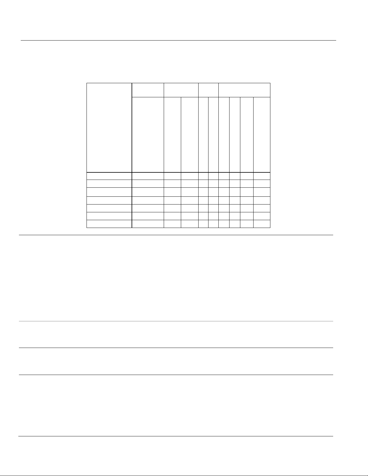
Operating
Voltage
Built-in Control
Options
GEB131.1P
●
– ● ● – – – –
–
GEB131.1U
●
– ● – ● – – –
–
GEB132.1U
●
– ● – ● ● – –
–
GEB136.1U
●
– ● – ● – ● –
–
GEB161.1P
●
● – ● – ● – –
●
GEB161.1U
●
● – – ● ● – –
●
GEB164.1U
●
● – – ● ● ● ●
–
Operating voltage 24 Vac ±20%
Control Signal
Input signal (wires 8-2) GEB16x
Feedback signal
Position output signal (wires 9-2) GEB16x
Function
Running torque 132 lb-in (15 Nm)
Document Number 155-318P25
May 1 9, 2014
Product Numbers
Table 1.
Control Cable
Product
Number
Specifications
Power Supply
24 Vac
24 Vac ±20%
Modulating (0 to 10 Vdc)
Floating
Plenum
Standard
Position Feedback
Dual Auxiliary Switches
Offset and Span
Input Signal Selectable
0 – 10 Vdc or 2-10 Vdc
Frequency 50/60 Hz
Power consumption
Running:
GEB16x 5 VA/4W
GEB13x 3 VA/3W
Holding:
GEB 16x 1 VA/1W
Equipment rating Class 2, in accordance with UL/CSA
Class III per EN 60730
Voltage-input 0 to 10 Vdc (max. 35 Vdc)
Input resistance >100K ohms
Voltage-output 0 to 10 Vdc
Maximum output current ±1 mA
Maximum torque 265 lb-in (30 Nm)
Runtime for 90° opening or closing
60 Hz 125 seconds
50 Hz 150 seconds
Nominal angle of rotation 90°
Maximum angular rotation 95°
Page 2 Siemens Industry, Inc.

OpenAir GEB Non-Spring Return, 24 Vac, 132 lb-in, Rotary Electronic Damper Actuators Technical Instructions
Mounting
Shaft size 1/4 to 3/4-inch (6.4 to 20.5 mm) dia.
Housing
Enclosure NEMA 1
Ambient conditions
Ambient temperature
Agency certification
UL60730 (to replace UL873)
Conformity
Low voltage directive 2006/95/EC
Auxiliary features
Document Number 155-318P25
May 1 9, 2014
1/4 to 1/2-inch (6.4 to 13 mm) square
Minimum shaft length 3/4-inch (20 mm)
IP54 according to EN 60 529
Material Die cast aluminum alloy
Gear lubrication Silicone free
Operation -25°F to 130°F (-32°C to 55°C)
Storage and transport -40°F to 158°F (-40°C to 70°C)
Ambient humidity (non-condensing) 95% rh
cUL certified to Canadian Standard
C22.2 No. 24-93
Product safety: Automatic electrical controls EN 60 730-2-14
for household and similar use (Type 1)
Electromagnetic compatibility (EMC) 2004/108/EC
Immunity for all models, except GEB132.xx EN61000-6-2
Immunity for GEB132.xx EN61000-6-1
Emissions for all models EN61000-6-3
Control signal adjustment
Offset (start point) Between 0 to 5V
Span Between 2 to 30V
Dual auxiliary switches
AC rating 24 to 250 Vac
AC 6A resistive,
AC 2A general purpose
DC rating 12 to 30 Vdc
DC 2A
Switch Range
Switch A 0 to 90° with 5° intervals
Recommended range usage 0 to 45°
Factory setting 5°
Switch B 0 to 90° with 5° intervals
Recommended range usage 45 to 90°
Factory setting 85°
Switching hysteresis 2°
Feedback potentiometer (GEB 132.1U) 0 to 1000 ohm <10 mA
Voltage UL-Class 2 (SELV/PELV for CE)
Siemens Industry, Inc. Page 3
Technical Instructions OpenAir GEB Non-Spring Return, 24 Vac,132 lb-in, Rotary Electronic Damper Actuators
Auxiliary features,
Miscellaneous
Pre-cabled connection 18 AWG
Document Number 155-318P25
May 1 9, 2014
Continued
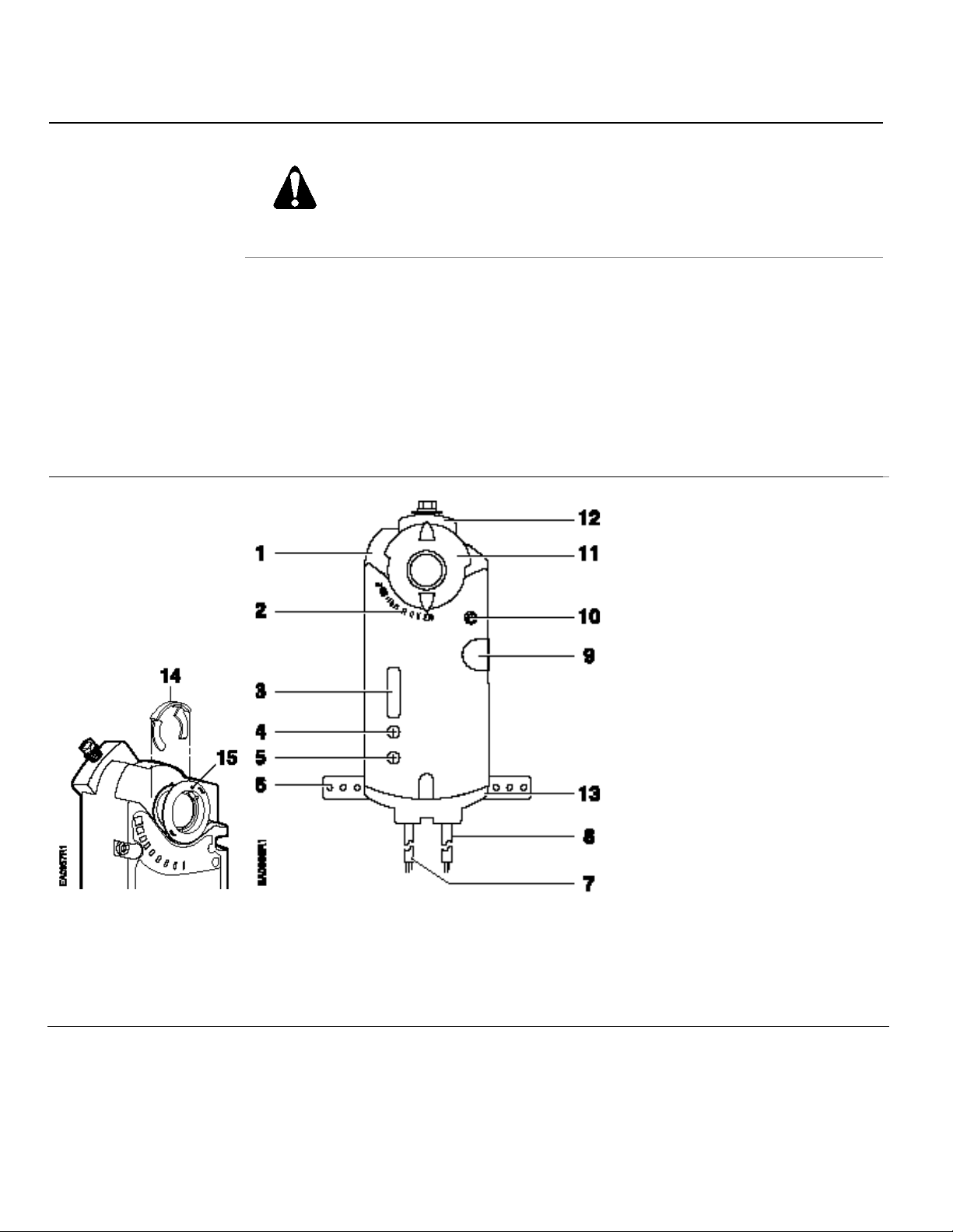
Actuator
Components
WARNING:
Apply only AC line voltage or only UL-Class 2 voltage (SELV for CE conformance) to
the switching outputs of both auxiliary switches A and B. Mixed operation is not
permissible. See Wiring for details.
NOTE: With plenum cables, only UL-Class 2 (SELV for CE) is permitted).
Cable length 3 feet (0.9m) length
Life cycle Designed for over 50,000 full strokes
at rated torque and temperature
Dimensions: Inches (mm) 8-3/8 H × 3-1/4 W × 2-2/3 D
(212 H × 83 W × 68 D)
Weight 2.2 lbs. (1 kg)
Country of Origin USA
Legend
1. Actuator housing
2. Positioning scale for angle of
rotation
3. DIP switches and cover
4. Span adjustment
Figure 1. Non-Spring Return Actuator
Components.
5. Offset (start point) adjustment
6. Mounting bracket
7. Connection cable for power
and control signals
8. Connection cable for auxiliary
switches or feedback
potentiometer
9. Manual override
10. Auxiliary switches A & B
11. Position indicator
12. Self centering shaft adapter
13. 1/2-inch NSPT conduit
connection
14. Shaft adapter locking clip
15. Position indicator adapter
Page 4 Siemens Industry, Inc.
OpenAir GEB Non-Spring Return, 24 Vac, 132 lb-in, Rotary Electronic Damper Actuators Technical Instructions
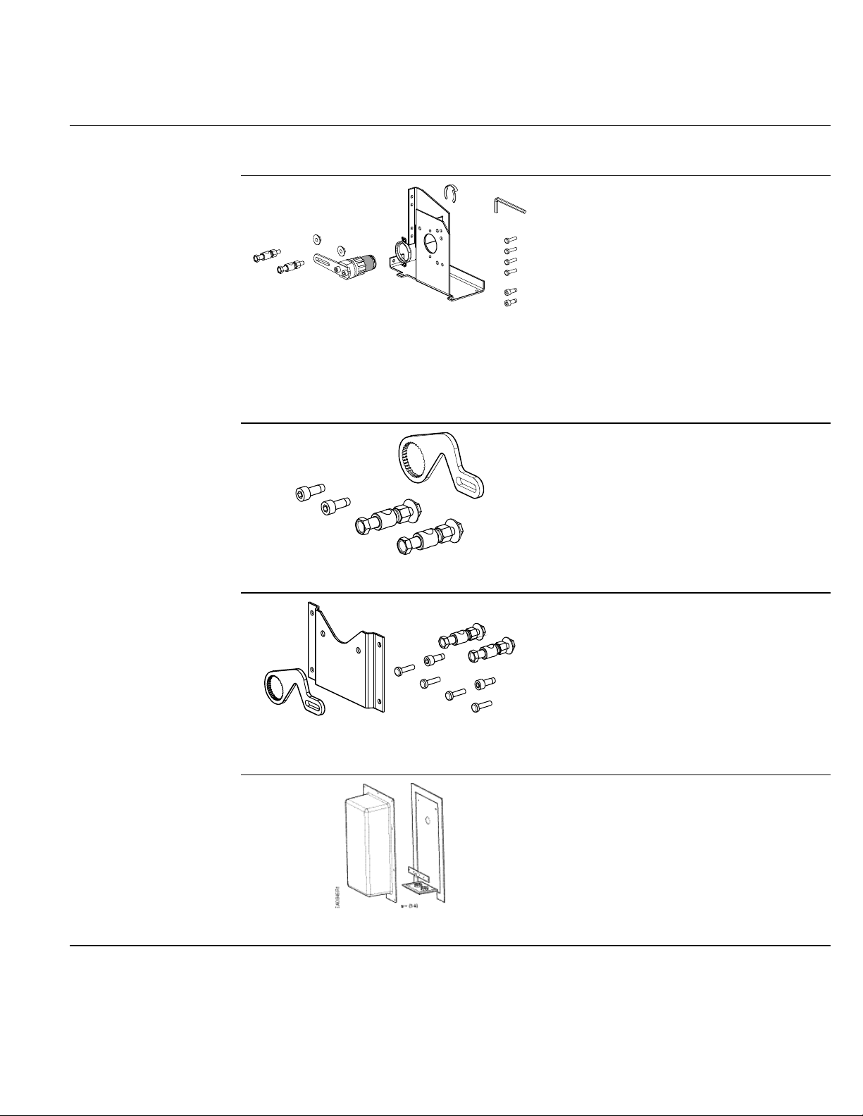
4614Z19
• Required mounting fasteners.
4614Z16
4614Z18
• Required mounting fasteners.
Document Number 155-318P25
May 1 9, 2014
Accessories
NOTE: The auxiliary switches, control signal adjustment, and feedback potentiometer
cannot be added in the field. Order the product number that includes the option(s).
ASK71.11: For in-the-air-stream
applications: Anywhere a foot-mounted
actuator can be mounted. Can also be
directly mounted to a damper frame with
louvers and vents and in applications where
use of the floor mount is not possible.
Kit contains:
• Crank arm to change the angular
Figure 2. Floor /Frame Mount Kit.
rotation into a linear stroke.
• Support bearing ring to minimize side
loading on the actuator’s output
bearing.
• Mounting bracket.
ASK71.13: Allows a direct-coupled actuator
to provide an auxiliary linear drive. Can be
used to simultaneously drive a set of
opposing or adjacent dampers with a single
actuator.
Kit contains:
• Crank arm to attach to the splined
hub of the shaft adapter.
Figure 3. Rotary to Linear Crank Arm Kit.
• Mounting fasteners.
ASK71.14: Allows economical mounting of
an OpenAir actuator to a variety of surfaces.
Should be used in applications where the
actuator can be rigid-surface mounted and a
linear stroke output is required.
Kit contains:
Figure 4. Rotary to Linear Crank Arm Kit
with Mounting Bracket.
• Crank arm to attach to the splined
hub of the shaft adapter.
• Mounting bracket.
ASK75.3U: GEB actuators are UL listed to
meet NEMA 3R requirements (a degree of
protection against rain, sleet, snow, and
damage from external ice formation) when
installed with ASK75.3U Weath er Shie ld and
outdoor-rated conduit fittings in the vertical
position.
Siemens Industry, Inc. Page 5
Figure 5. NEMA 3RWeath er Shield.
 Loading...