

Page 1
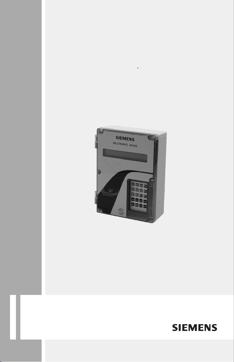
Integrators
Milltronics BW500 and BW500/L
Operating Instructions 12/2010
Milltronics
Page 2

Safety Guidelines: Warning notices must be observed to ensure personal safety as well as that of
others, and to protect the product and the connected equipment. These warning notices are
accompanied by a clarification of the level of caution to be observed.
Qualified Personnel: This device/system may only be set up and operated in conjunction with this
manual. Qualified personnel are only authorized to install and operate this equipment in accordance with
established safety practices and standards.
Unit Repair and Excluded Liability:
• The user is responsible for all changes and repairs made to the device by the user or the user’s
agent.
• All new components are to be provided by Siemens Milltronics Process Instruments.
• Restrict repair to faulty components only.
• Do not reuse faulty components.
Warning: Cardboard shipping package provides limited humidity and moisture protection. This product
can only function properly and safely if it is correctly transported, stored, installed, set up, operated, and
maintained.
This product is intended for use in industrial areas. Operation of this equipment in a residential area
may cause interference to several frequency based communications.
Note: Always use product in accordance with specifications.
Copyright Siemens AG 2010. All Rights
Disclaimer of Liability
Reserved
This document is available in bound version and in
electronic version. We encourage users to purchase
authorized bound manuals, or to view electronic
versions as designed and authored by Siemens
Milltronics Process Instruments. Siemens Milltronics
Process Instruments will not be responsible for the
contents of partial or whole reproductions of either
bound or electronic versions.
While we have verified the contents of this
manual for agreement with the
instrumentation described, variations remain
possible. Thus we cannot guarantee full
agreement. The contents of this manual are
regularly reviewed and corrections are
included in subsequent editions. We welcome
all suggestions for improvement.
Technical data subject to change.
MILLTRONICS®is a registered trademark of Siemens Milltronics Process Instruments.
Contact SMPI Technical Publications European Authorized Representative
at the following address:
Technical Publications Siemens AG
Siemens AG Industry Sector
Siemens Milltronics Process Instruments 76181 Karlsruhe
1954 Technology Drive, P.O. Box 4225 Deutschland
Peterborough, Ontario, Canada, K9J 7B1
Email: [email protected]
• For a selection of Siemens Milltronics level measurement manuals, go to:
www. siemens.com/processautomation. Under Process Instrumentation, select
Measurement
• For a selection of Siemens Milltronics weighing manuals, go to:
www. siemens.com/processautomation. Under Weighing Technology, select
Weighing Systems
and then go to the manual archive listed under the product family.
and then go to the manual archive listed under the product family.
Level
Continuous
© Siemens AG 2010
Page 3

Table of Contents
Safety Notes .............................................................................................................................................1
The Manual ...............................................................................................................................................1
Technical Support ....................................................................................................................................2
Milltronics BW500 and BW500/L ..................................................................................... 3
Milltronics BW500 ...................................................................................................................................3
Milltronics BW500/L ...............................................................................................................................3
Milltronics BW500 and BW500/L features .......................................................................................3
Specifications ......................................................................................................................5
Installation ........................................................................................................................... 9
Dimensions ...............................................................................................................................................9
Layout ......................................................................................................................................................11
Optional Plug-ins ...................................................................................................................................12
SmartLinx7 Module .....................................................................................................................12
mA I/O board .................................................................................................................................12
Interconnection .....................................................................................................................................14
System Diagram .........................................................................................................................14
Scale – One Load Cell ................................................................................................................15
Scale – Two Load Cells ..............................................................................................................16
Scale – Four Load Cells .............................................................................................................17
Scale – Six Load Cells ................................................................................................................18
Scale – LVDT .................................................................................................................................19
Speed .......................................................................................................................................................20
Constant Speed (No Sensor) ....................................................................................................20
Main Speed Sensor ....................................................................................................................20
Auxiliary Speed Sensor .............................................................................................................21
Auxiliary Inputs .....................................................................................................................................22
Auto Zero .................................................................................................................................................22
RS-232 Port 1 ..........................................................................................................................................22
Printers ...........................................................................................................................................22
Computers and Modems ...........................................................................................................23
Remote Totalizer ....................................................................................................................................23
mA Output 1 ............................................................................................................................................23
Relay Output ...........................................................................................................................................24
RS-485 Port 2 ..........................................................................................................................................25
Daisy Chain ...................................................................................................................................25
Terminal Device ............................................................................................................................25
RS-232 Port 3 ..........................................................................................................................................25
Power Connections ..............................................................................................................................26
mA I/O Board connections ........................................................................................................27
Installing/replacing the back-up battery .........................................................................................27
Table of Contents
Start Up ............................................................................................................................... 28
Keypad .....................................................................................................................................................28
PROGRAM Mode ..................................................................................................................................29
i
Page 4

PROGRAM Mode Display .........................................................................................................29
To enter PROGRAM mode: .......................................................................................................29
RUN Mode ....................................................................................................................................31
Initial Start Up ........................................................................................................................................31
Power Up .......................................................................................................................................31
Programming ................................................................................................................................31
Press ..............................................................................................................................................32
Table of C on t en ts
Load Cell Balancing ..............................................................................................................................35
Typical two load cell belt scale ................................................................................................35
Zero Calibration ...........................................................................................................................38
RUN Mode ....................................................................................................................................40
Recalibration .....................................................................................................................41
Belt Speed Compensation ..................................................................................................................41
Material Tests ........................................................................................................................................42
% Change ......................................................................................................................................42
Material Test .................................................................................................................................44
Design Changes .....................................................................................................................................45
Recalibration ...........................................................................................................................................45
Routine Zero .................................................................................................................................45
Initial Zero .....................................................................................................................................46
Direct Zero ....................................................................................................................................47
Auto Zero .......................................................................................................................................47
Routine Span ................................................................................................................................48
Initial Span ....................................................................................................................................49
Direct Span ...................................................................................................................................50
Multispan ......................................................................................................................................50
Online Calibration ..................................................................................................................................53
Factoring .................................................................................................................................................58
Linearization ...........................................................................................................................................59
Operation ............................................................................................................................ 63
Load Sensing ..........................................................................................................................................63
Speed Sensing .......................................................................................................................................63
Differential Speed Detection...............................................................................................................63
Moisture Compensation ......................................................................................................................64
Incline Compensation ..........................................................................................................................65
Modes of Operation ..............................................................................................................................65
Damping ...................................................................................................................................................66
mA I/O (0/4-20 mA) ................................................................................................................................66
Relay Output ...........................................................................................................................................67
Totalization ..............................................................................................................................................68
PID Control .........................................................................................................................71
Hardware .................................................................................................................................................71
Connections ............................................................................................................................................71
Setpoint Controller – Rate Control ..........................................................................................72
Setpoint Controller – Load Control ..........................................................................................72
Setpoint Controller – Master/Slave Control .........................................................................73
Setpoint Controller – Rate and Load Control .......................................................................74
ii
Page 5

Setup and Tuning ...................................................................................................................................74
P
Proportional Control (Gain),
Integral Control (Automatic Reset), I ......................................................................................75
Derivative Control (Pre-Act or Rate), D ..................................................................................76
Feed Forward Control, F ............................................................................................................76
PID Setup and Tuning ...........................................................................................................................77
Initial Start-Up ..............................................................................................................................77
Programming ..........................................................................................................................................80
.................................................................................................. 74
Batching .............................................................................................................................. 83
Connections ............................................................................................................................................84
Typical Ladder Logic ...................................................................................................................84
Programming ..........................................................................................................................................84
Operation .................................................................................................................................................85
Pre-act Function ..........................................................................................................................85
Communications ...............................................................................................................86
BW500 and BW500/L and SmartLinx® ...........................................................................................87
Connection ..............................................................................................................................................87
Wiring Guidelines ........................................................................................................................87
Configuring Communication Ports ....................................................................................................88
P770 Serial protocols ..................................................................................................................88
P771 Protocol address ................................................................................................................89
P772 Baud Rate ............................................................................................................................89
P773 Parity .....................................................................................................................................89
P774 Data bits ...............................................................................................................................90
P775 Stop bits ...............................................................................................................................90
P778 Modem attached ...............................................................................................................90
P779 Modem idle time ...............................................................................................................91
P780 RS-232 Transmission interval .........................................................................................91
P781 Data message ....................................................................................................................92
P799 Communications Control .................................................................................................92
Dolphin Protocol ....................................................................................................................................93
Dolphin Plus Screen Shot ..........................................................................................................93
Modbus RTU/ASCII Protocol ..............................................................................................................94
How Modbus Works ...................................................................................................................94
Modbus RTU vs. ASCII ...............................................................................................................95
Modbus Format ............................................................................................................................95
Modbus Register Map ...............................................................................................................95
Modbus Register Map (cont’d) ................................................................................................98
Modems ...................................................................................................................................... 107
Error Handling ........................................................................................................................... 109
Table of Contents
Parameters ....................................................................................................................... 111
Start Up (P001 to P017) ...................................................................................................................... 111
Relay/Alarm Function (P100 - P117) ................................................................................................116
mA I/O Parameters (P200 - P220) ....................................................................................................119
Calibration Parameters (P295 – P360) ............................................................................................125
Online Calibration Options (P355 to P358) .....................................................................................126
Linearization Parameters (P390 - P392) .........................................................................................129
iii
Page 6

Proportional Integral Derivative (PID) Control Parameters (P400 – P419) ............................130
Batch Control (P560 – P568) ..............................................................................................................134
Totalization (P619 - P648) ...................................................................................................................136
ECal Parameters (P693 – P698) ........................................................................................................141
Communication (P740 - P799) ...........................................................................................................143
SmartLinx Hardware Testing ............................................................................................................143
Test and Diagnostic (P900 - P951) ...................................................................................................145
Troubleshooting ............................................................................................................... 148
Table of C on t en ts
Generally ......................................................................................................................................148
Specifically ..................................................................................................................................148
Certification ..................................................................................................................... 150
Parameters unlocked when certification switch is set: ..................................................150
Certification Printing .................................................................................................................151
Glossary ............................................................................................................................ 152
Appendix I ........................................................................................................................ 155
Memory Backup ..................................................................................................................................155
Software Updates ...............................................................................................................................155
Calibration Criteria ..............................................................................................................................155
Zero ...............................................................................................................................................155
Span ..............................................................................................................................................155
PID Systems ................................................................................................................................155
Appendix II: Software Revision History ..................................................................... 156
Index .................................................................................................................................. 160
iv
Page 7

Safety Notes
Special attention must be paid to warnings and notes highlighted from the rest of the text
by grey boxes.
WARNING means that failure to observe the necessary precautions
can result in death, serious injury, and/or considerable material
damage.
Note: means important information about the product or that part of the operating
manual.
The Manual
Note:
• The Milltronics BW500 and BW500/L are to be used only in the manner outlined in
this instruction manual.
• These products are intended for use in industrial areas. Operation of this
equipment in a residential area may cause interference to several frequency
based communications.
This instruction manual covers the operation, installation, and maintenance of Milltronics
BW500 and BW500/L.
Please refer to this manual for proper installation and operation of your BW500 or
BW500/L belt scale integrator. As BW500 and BW500/L must be connected to a belt
scale, and optionally a speed sensor, refer to their manuals as well.
The manual is designed to help you get the most out of your BW500 and BW500/L, and it
provides information on the following:
• How to install the unit
• How to program the unit
• How to operate the keypad
and read the display
• How to do an initial Start Up
• How to optimize and
maintain accurate operation
of the unit
• Outline diagrams
• Wiring diagrams
• Parameter values
• Parameter uses
• MODBUS® register mapping
• Modem configuration
Introduction
We always welcome suggestions and comments about manual content, design, and
accessibility. Please direct your comments to [email protected].
For the complete library of Siemens Milltronics manuals, go to
www. siemens.com/weighing.
7ML19985DK05Milltronics BW500 and BW500/L - OPERATING INSTRUCTIONS Page 1
Page 8

Technical Support
Support is available 24 hours a day.
To find your local Siemens Automation Office address, phone number and fax number go
to:
www.siemens.com/automation/partner
• Click on the tab Contacts by Product then find your product group (+Process
Automation > +Process Instrumentation > +Level Measuring Instruments).
• Select the team Technical Support. Click on Next.
• Click on the appropriate continent, then select the country followed by the city. Click
on Next.
For online technical support go to:
www.siemens.com/automation/support-request
Introduction
• Enter the device name (SITRANS WW100) or order number, then click on Search,
and select the appropriate product type. Click on Next.
• You will be prompted to enter a keyword describing your issue. Then either browse
the relevant documentation, or click on Next to email a detailed description of your
issue to Siemens Technical Support staff.
Siemens A&D Technical Support Center: phone+49 180 50 50 222
fax +49 180 50 50 223
Page 2 Milltronics BW500 and BW500/L - OPERATING INSTRUCTIONS 7ML19985DK05
Page 9

Milltronics BW500 and BW500/L
Milltronics BW500
The Milltronics BW500 is a full-featured integrator for use with belt scales and
weighfeeders. The speed and load signals from the conveyor and scale, respectively, are
processed to derive rate of material flow, and totalization. The primary values of speed
and load, and the derived values of rate and total are available for display on the local
LCD, or as output in the form of analog mA, alarm relay and remote totalization.
Milltronics BW500/L
The Milltronics BW500/L is an integrator for use in basic belt scale or weighbelt
applications. The speed and load signals from the conveyor and scale, respectively, are
processed to derive rate of material flow, and totalization. The BW500/L does not include
the advanced feature set for control.
Milltronics BW500 and BW500/L features
BW500 and BW500/L support Siemens Milltronics Dolphin Plus software and Modbus
protocol on the two RS-232 ports and the RS-485 port for communication to customer PLC
or computer. BW500 and BW500/L also support Siemens SmartLinx®for popular
industrial communication systems.
Reliable and robust user interface
• multi-field LCD display
• local keypad
Instrumentation I/O
BW500 BW500/L
remote totalizer contacts 2 2
programmable relays 5 2
programmable discrete inputs 5 5
mA input
mA output
a)
The optional mA I/O board is required for 3 outputs: PID control, moisture, and
incline compensation.
3: rate, load, speed or PID
2 for PID
a)
trol
control
a
con-
1: rate, load, speed
Introduction
Popular Windows
• two RS-232 ports
• one RS-485 port
7ML19985DK05Milltronics BW500 and BW500/L - OPERATING INSTRUCTIONS Page 3
®and Industrial communications
Page 10

Individual port configuration for:
• Dolphin Plus
•Modbus ASCII
•Modbus RTU
•Printer
• SmartLinx®compatible
Controls and operation functions
load linearization
BW500 BW500/L
TT
auto zero
PID control
batch control
Introduction
multispan operation
moisture compensation
incline compensation
differential speed detection
a)
a)
a
a
The optional mA I/O board is required for 3 outputs: PID control, moisture, and
incline compensation.
TT
T
T
T
T
T
fixed
fixed
T
Page 4 Milltronics BW500 and BW500/L - OPERATING INSTRUCTIONS 7ML19985DK05
Page 11

Specifications
Power
• 100/115/200/230 V AC ±15%, 50/60 Hz, 31 VA
• fuse, FU1 2AG, Slo Blo, 2 A, 250 V or equivalent
Application
• compatible with Siemens belt scales or equivalent 1, 2, 4, or 6 load cell scales
(1 or 2 load cell scales for BW500/L)
• compatible with LVDT equipped scales, with use of optional interface board
Accuracy
• 0.1% of full scale
Resolution
• 0.02% of full scale
Environmental
location indoor/outdoor
altitude 2000 m max.
ambient temperature -20 to 50 °C (-5 to 122 °F)
relative humidity suitable for outdoor (Type 4X / NEMA 4X /IP 65
enclosure)
installation category II
pollution degree 4
Specifications
Enclosure
• Type 4X / NEMA 4X / IP65
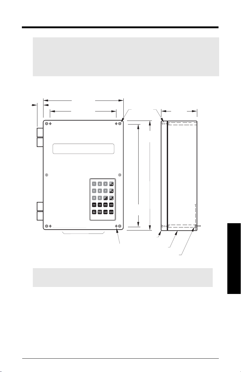
• 285 mm W x 209 mm H x 92 mm D (11.2" W x 8.2" H x 3.6" D)
• polycarbonate
Programming
• via local keypad and/or Dolphin Plus interface
Display
• illuminated 5 x 7 dot matrix liquid crystal display with 2 lines of 40 characters each
7ML19985DK05Milltronics BW500 and BW500/L - OPERATING INSTRUCTIONS Page 5
Page 12

Specifications
Memory
• program and parameters stored in non-volatile FLASH ROM, upgradable via Dolphin
Plus interface
• Runtime totalizers and clock settings
PBD-2020035 or use equivalent 3V Lithium battery (BR 2335), 5 year life
1)
stored in battery backed RAM, battery P/N
Inputs
load cell 0 - 45 mV DC per load cell
speed sensor pulse train 0 V low, 5-15 V high, 1 to 3000 Hz,
or
open collector switch,
or
relay dry contact
auto zero dry contact from external device
mA see optional mA I/O board
auxiliary 5 discrete inputs for external contacts, each
programmable for either display scrolling, totalizer 1
reset, zero, span, multispan, print, batch reset, or
PID function.
1
Outputs
mA
• 1 programmable 0/4 - 20 mA, for rate, load, and speed output
• optically isolated
• 0.1% of 20 mA resolution
•750 load max
• see optional mA I/O board
1
load cell 10 V DC compensated excitation for strain gauge
type, 6 cells max, BW500 has 4 independent inputs,
BW500/L has 2. The maximum load, in either case,
must not exceed 150 mA.
speed sensor 12 V DC, 150 mA max excitation for each speed
sensor
remote totalizer 1
• contact closure 10 - 300 ms duration
• open collector switch rated 30 V DC, 100 mA max
remote totalizer 2
• contact closure 10 - 300 ms duration
• open collector switch rated 240 V AC/DC, 100 mA max
1)
Not available with BW500/L.
Page 6 Milltronics BW500 and BW500/L - OPERATING INSTRUCTIONS 7ML19985DK05
Page 13

relay output
• BW500 5 alarm/control relays, 1 form 'A' SPST relay contact per
relay, rated 5 A at 250 V AC, non-inductive
• BW500/L 2 alarm relays
Communications
•two RS-232 ports
• one RS-485 port
• SmartLinx® compatible (see
Options
below)
Cable
one load cell
• non-sensing Belden 8404, 4 wire shielded, 20 AWG or equivalent, 150 m
(500 ft.) max.
• sensing Belden 9260, 6 wire shielded, 20 AWG or equivalent,
300 m (1000 ft.) max.
two/four/six
• non-sensing Belden 9260, 6 wire shielded, 20 AWG or equivalent,
• sensing Belden 8418, 8 wire shielded, 20 AWG or equivalent,
speed sensor Belden 8770, 3 wire shielded, 18 AWG or equivalent,
auto zero Belden 8760, 1 pair, twisted/shielded, 18 AWG, 300 m
remote total Belden 8760, 1 pair, twisted/shielded, 18 AWG, 300 m
1)
load cells
150 m (500 ft.) max.
300 m (1000 ft.) max.
300m (1000 ft.)
(1000 ft.) max.
(1000 ft.) max.
Specifications
Options
Speed Sensor Siemens MD-36/36A/256 or 2000A, RBSS, TASS,
WS100, or WS300, or compatible
Dolphin Plus Siemens Windows®based software interface (refer
to associated product documentation)
SmartLinx®Modules protocol specific modules for interface with popular
industrial communications systems (refer to
associated product documentation)
1)
For four or six load cell scales, run two separate cables of the two load cell configuration. Four/
six load cells not available with BW500/L.
7ML19985DK05Milltronics BW500 and BW500/L - OPERATING INSTRUCTIONS Page 7
Page 14

mA I/O board
• inputs
•outputs
• output supply isolated 24 V DC at 50 mA, short circuit protected
LVDT interface card for interface with LVDT based scales
1)
- 2 programmable 0/4 – 20 mA for PID, control, incline,
and moisture compensation, and online calibration
- optically isolated
- 0.1% of 20 mA resolution
-200 input impedance
- 2 programmable 0/4 – 20 mA for PID control, rate, load,
and speed output
- optically isolated
- 0.1% of 20 mA resolution
-750 load max
Weight
• 2.6 kg (5.7 lb.)
Approvals
BW500 BW500/L
Specifications
CEa), CSA US/C, C-TICK,
GOST
Legal for Canadian Trade Measurement Canada
approved
Legal for US Trade - NTEP
approved
Legal for European Trade - MID
approved
Legal for International Trade OIML approved
a)
EMC performance available upon request
1)
Not available with BW500/L.
TT
T
T
T
T
Page 8 Milltronics BW500 and BW500/L - OPERATING INSTRUCTIONS 7ML19985DK05
Page 15
Installation
209 mm
(8.2")
172 mm
(6.8")
lid screws
(6 pieces)
92 mm
(3.6")
16 mm (0.6")
285 mm
(11.2")
lid
enclosure
customer
mounting screw
mounting hole
(4 places)
Conduit entry area.
Recommend drilling the enclosure with
a hole saw and the use of suitable cable
glands to maintain ingress rating.
267 mm
(10.5")
Note:
• Installation shall only be performed by qualified personnel and in
accordance with local governing regulations.
• This product is susceptible to electrostatic shock. Follow proper grounding
procedures.
Dimensions
Note: Non metallic enclosure does not provide grounding between connections.
Use grounding type bushings and jumpers.
7ML19985DK05Milltronics BW500 and BW500/L - OPERATING INSTRUCTIONS Page 9
Installation
Page 16

Mounting the Enclosure
mounting holes
1. Remove the lid screws and open the lid to reveal the mounting holes.
2. Mark and drill four holes in the mounting
surface for the four screws (customer supplied).
3. Fasten with a long screwdriver.
Please note:
• Recommended mounting: directly to wall or to
electrical cabinet back panel
• Recommended mounting screws: #6
• If alternate mounting surface is used, it MUST
be able to support four times the weight of the
unit.
Installation
Page 10 Milltronics BW500 and BW500/L - OPERATING INSTRUCTIONS 7ML19985DK05
Page 17
Layout
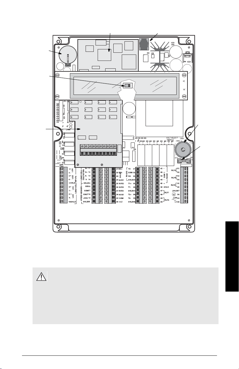
optional
Analog I/O
board
2
certification
switch
1
battery,
memory
back up
optional SmartLinx module
3
port 3 (RJ-11)
power
switch
fuse
FU1
1. Applicable for trade approvals
2. Not available for BW500/L
3. To reduce communication interference, route SmartLinx®cable along right side of
enclosure wall.
WARNING:
• All field wiring must have insulation suitable for at least 250 V.
• DC terminals shall be supplied from SELV source in accordance with IEC
10101-1 Annex H.
• Relay contact terminals are for use with equipment having no accessible live parts
and wiring having insulation suitable for at least 250 V.
• The maximum allowable working voltage between adjacent relay contact shall be
250 V.
Installation
7ML19985DK05Milltronics BW500 and BW500/L - OPERATING INSTRUCTIONS Page 11
Page 18

Optional Plug-ins
SmartLinx7 Module
BW500 and BW500/L is software/hardware ready to accept the optional Siemens
SmartLinx® communications module that provides an interface to one of several popular
industrial communications systems.
BW500 and BW500/L may be shipped to you without a SmartLinx®module, for
installation at a later date.
If you are ready to install your SmartLinx®
the instructions as outlined.
Installation
1. Isolate power and voltages applied to the BW500 and BW500/L
2. Open the lid
3. Install the module by mating the connectors and secure in place using the two
screws provided
4. Route communication cable to SmartLinx®module along the right side of the
enclosure wall. This route will reduce communication
Note: Refer to the SmartLinx® documentation for any required hardware settings
prior to closing the lid.
5. Close the lid.
6. Apply power and voltage to the BW500 and BW500/L.
module, or want to change it, please follow
Refer to:
• SmartLinx®Module in the
P750 – P769 SmartLinx® Module Specific Parameters
•
manual
• the SmartLinx® manual for wiring
mA I/O board
Installation
BW500 is software/hardware ready to accept the optional mA I/O board. The mA I/O
board provides 2 programmable 0/4-20 mA outputs, 2 programmable 0/4-20 mA inputs and
a nominal 24 V DC supply for loop powered devices.
BW500 may be shipped to you without an mA I/O board, for installation at a later date.
If you are ready to install your mA I/O board, please follow the instructions as outlined.
1)
Not available with the BW500/L
Page 12 Milltronics BW500 and BW500/L - OPERATING INSTRUCTIONS 7ML19985DK05
1)
Specifications
section on page 5
on page 143 in this
Page 19
Installation
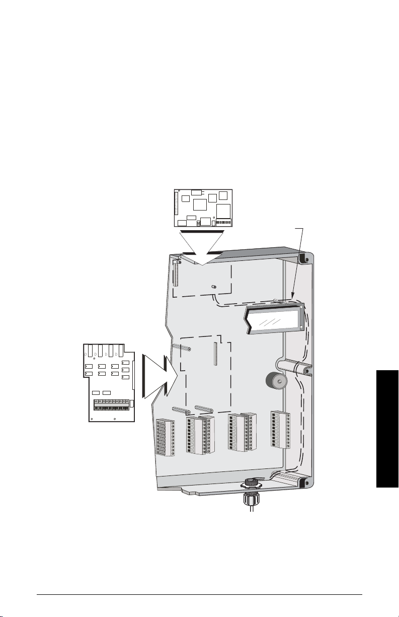
mA I/O board
SmartLinx®
route SmartLinx®
cable along right
hand wall
1. Isolate power and voltages applied to the BW500
2. Open the lid
3. Install the board by mating the connectors and secure the card in place using
4. Close the lid
5. Apply power and voltage to the BW500
Refer to:
•
•
•
•
the three screws provided
Specifications
mA I/O board
on page 8
connections on page 27
mA I/O Parameters (P200 - P220)
mA I/O (0/4-20 mA)
in the
Operation
on page 119
section on page 66
Installation
7ML19985DK05Milltronics BW500 and BW500/L - OPERATING INSTRUCTIONS Page 13
Page 20
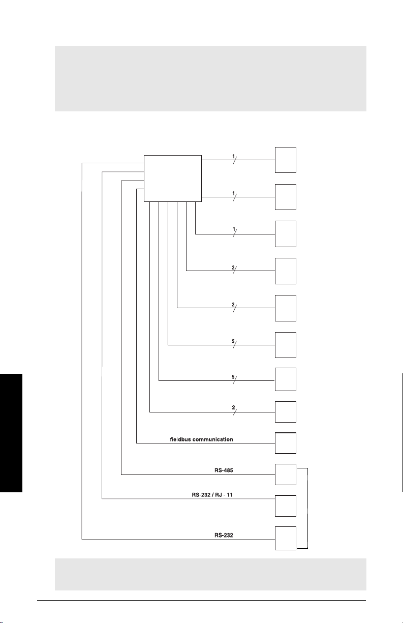
Interconnection
Milltronics
BW500 and BW500/
L
optional SmartLin x®
belt scale, see
Specifications
speed sensor,
optional, see
Specifications
mA output to
customer device
mA input from
customer device
(optional I/O board
required)
relay output, to
customer device
(2 for BW500/L)
auxiliary inputs
customer remote
totalizer
optional fieldbus
connection
(SmartLinx card
required)
mA output to
customer device
(optional I/O board
required)
communication
ports can be
configured for
Siemens
Milltronics Dolphin
Plus, print data, or
Modbus ASCII or
RTU protocol
Note:
• Wiring may be run via common conduit. However, these may not be run in the
same conduit as high voltage contact or power wiring.
• Ground shield at one point only.
• Insulate at junctions to prevent inadvertent grounding.
System Diagram
Installation
Note: Typical system capability. Not all components or their maximum quantity may
be required
Page 14 Milltronics BW500 and BW500/L - OPERATING INSTRUCTIONS 7ML19985DK05
.
Page 21
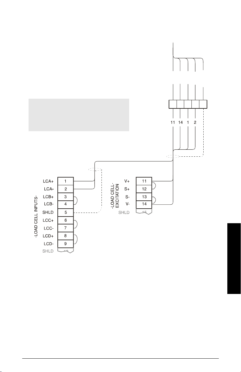
Scale – One Load Cell
Siemens
Belt Scale
load cell
customer
junction box
R
E
D
B
L
K
G
R
N
W
H
T
S
H
L
D
*
Note: Colour code for load cells used on
Siemens weighfeeders may be different than
shown. Please refer to the weighfeeder
wiring diagram.
*Where separation between the BW500 and BW500/L and belt scale exceeds 150 m
(500 ft.), or legal for trade certification:
1. remove jumpers from BW500 and BW500/L terminal 11/12 and 13/14
2. run additional conductors from:
BW500 and BW500/L terminal 12 to scale `red'
BW500 and BW500/L terminal 13 to scale `blk'
If the load cell wiring colours vary from those shown, or if extra wires are provided,
consult Siemens.
7ML19985DK05Milltronics BW500 and BW500/L - OPERATING INSTRUCTIONS Page 15
Installation
Page 22
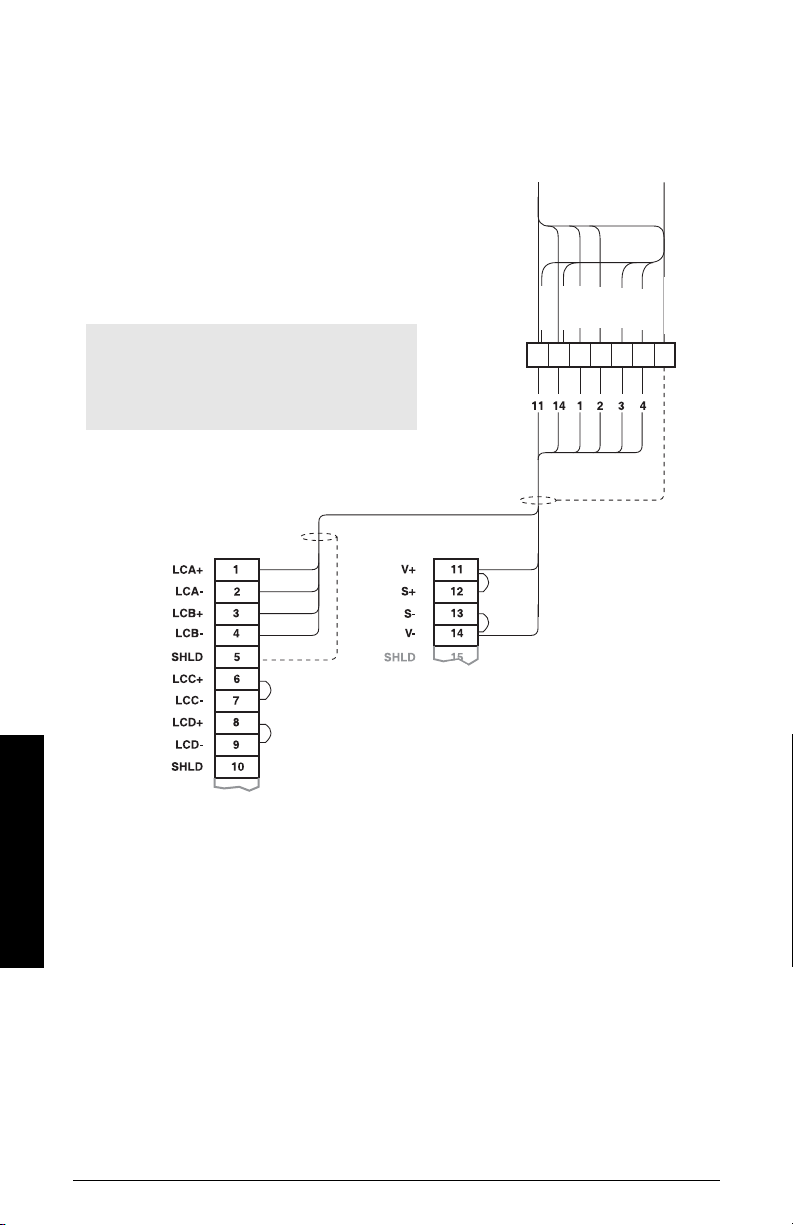
Scale – Two Load Cells
load cell
A
load cell
B
customer
junction box
Siemens
Belt Scale
R
E
D
B
L
K
G
R
N
W
H
T
S
H
L
D
W
H
T
G
R
N
Note: Colour code for load cells used on
Siemens weighfeeders may be different than
shown. Please refer to the weighfeeder
wiring diagram.
- LOAD CELL INPUTS -
- LOAD CELL -
EXCITATION
integrator
Where separation between the BW500 and BW500/L and belt scale exceeds 150 m
Installation
(500 ft.), or legal for trade certification:
1. remove jumpers from BW500 and BW500/L terminal 11/12 and 13/14
2. run additional conductors from:
BW500 and BW500/L terminal 12 to scale `red'
BW500 and BW500/L terminal 13 to scale `blk'
If the load cell wiring colours vary from those shown, or if extra wires are provided,
consult Siemens.
Page 16 Milltronics BW500 and BW500/L - OPERATING INSTRUCTIONS 7ML19985DK05
Page 23
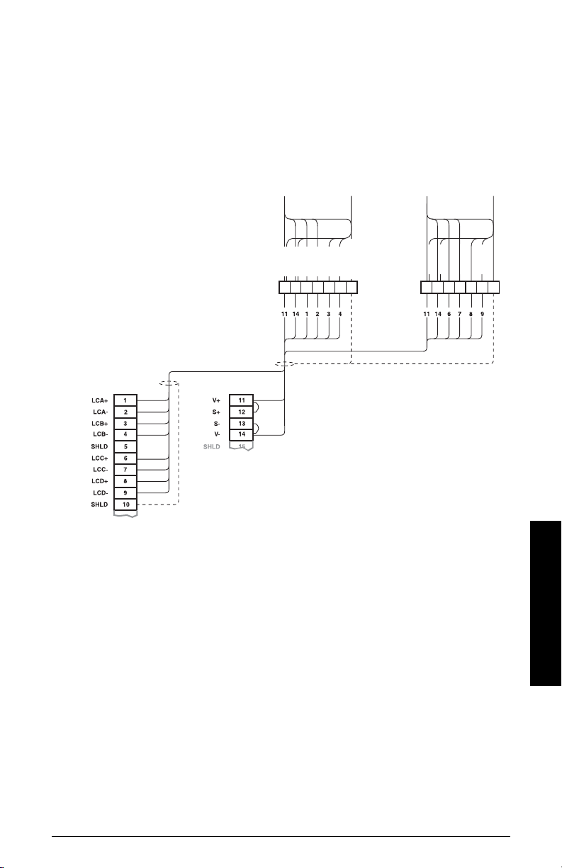
Scale – Four Load Cells
load
cell
A
load
cell
B
load
cell
C
load
cell
D
Siemens
Belt Scale
customer
junction box
integrator
R
E
D
G
R
N
S
H
L
D
W
H
T
G
R
N
B
L
K
W
H
T
R
E
D
G
R
N
S
H
L
D
W
H
T
G
R
N
B
L
K
W
H
T
- LOAD CELL INPUTS -
- LOAD CELL -
EXCITATION
1)
Where separation between the BW500 and belt scale exceeds 150 m (500 ft.), or legal for
trade certification:
1. remove jumpers from BW500 terminal 11/12 and 13/14
2. run additional conductors from:
BW500 terminal 12 to scale `red'
BW500 terminal 13 to scale `blk'
If the load cell wiring colours vary from those shown, or if extra wires are provided,
consult Siemens.
1)
Not available with the BW500/L.
7ML19985DK05Milltronics BW500 and BW500/L - OPERATING INSTRUCTIONS Page 17
Installation
Page 24
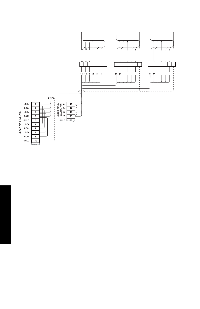
Scale – Six Load Cells
412
3
412
3
load
cell
A
Siemens
Belt Scale
customer
junction box
integrator
load
cell
B
load
cell
D
load
cell
E
load
cell
C
load
cell
F
R
E
D
G
R
N
S
H
L
D
W
H
T
G
R
N
B
L
K
W
H
T
R
E
D
G
R
N
S
H
L
D
W
H
T
G
R
N
B
L
K
W
H
T
R
E
D
G
R
N
S
H
L
D
W
H
T
G
R
N
B
L
K
W
H
T
1)
Where separation between the BW500 and belt scale exceeds 150 m (500 ft.), or legal for
trade certification:
1. remove jumpers from BW500 terminal 11/12 and 13/14
2. run additional conductors from:
Installation
BW500 terminal 12 to scale `red'
BW500 terminal 13 to scale `blk'
If the load cell wiring colours vary from those shown, or if extra wires are provided,
consult Siemens.
1)
Not applicable for the BW500/L.
Page 18 Milltronics BW500 and BW500/L - OPERATING INSTRUCTIONS 7ML19985DK05
Page 25
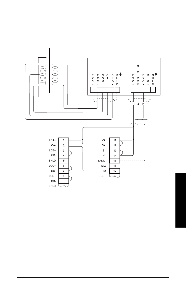
Scale – LVDT
belt scale with
LVDT
Siemens Milltronics LVDT Conditioner
maximum cable run LVDT to Conditioner 300 m (1000 ft)
Siemens Milltronics
BW500 and BW500/L
- LOAD CELL INPUTS -
- LOAD CELL -
EXCITATION
Where separation between the BW500 and BW500/L and LVDT conditioner exceeds 150
m (500 ft):
1. remove jumpers from BW500 and BW500/L terminal 11/12 and 13/14
2. run additional conductors from:
BW500 terminal 12 to integrator terminal block ‘+EXC’
BW500 terminal 13 to integrator terminal block ‘-EXC’
For further connection information on specific LVDTs consult Siemens.
7ML19985DK05Milltronics BW500 and BW500/L - OPERATING INSTRUCTIONS Page 19
Installation
Page 26
Speed
wht
red
blk
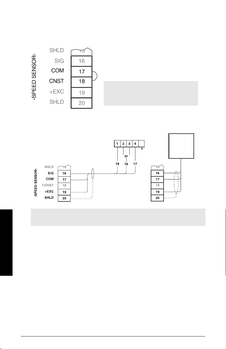
Constant Speed (No Sensor)
If a speed sensor is not used, a jumper or contact
closure must be connected across BW500 and
BW500/L terminals 17 / 18 when the conveyor is
running. If a speed sensor is used, ensure that the
jumper is removed.
Main Speed Sensor
Note: With contact closed or jumpered
when the conveyor is idle, the integrator will
continue totalizing
.
Installation
WS Series
RBSS or ENCODER
Note: Shields are common, but not grounded to chassis. Run cable shields through
SHLD terminals and ground at BW500 and BW500/L only.
Connect BW500 and BW500/L terminal 16 to speed sensor terminal:
• ‘2’ for clockwise speed sensor shaft rotation
• ‘3’ for counter-clockwise speed sensor shaft rotation.
Speed sensor shaft rotation is viewed from the front cover of the speed sensor
enclosure.
Input device in the form of open collector transistor or dry contact across BW500 and
BW500/L terminals 16 / 17 will also serve as a suitable speed signal.
If a speed sensor other than the models shown is supplied, consult with Siemens for
details.
A second speed sensor input can be added using the Auxiliary inputs: the second speed
input allows calculation of Differential Speed. For more information, see
(P270)
on page 122.
Auxiliary Inputs
Page 20 Milltronics BW500 and BW500/L - OPERATING INSTRUCTIONS 7ML19985DK05
Page 27
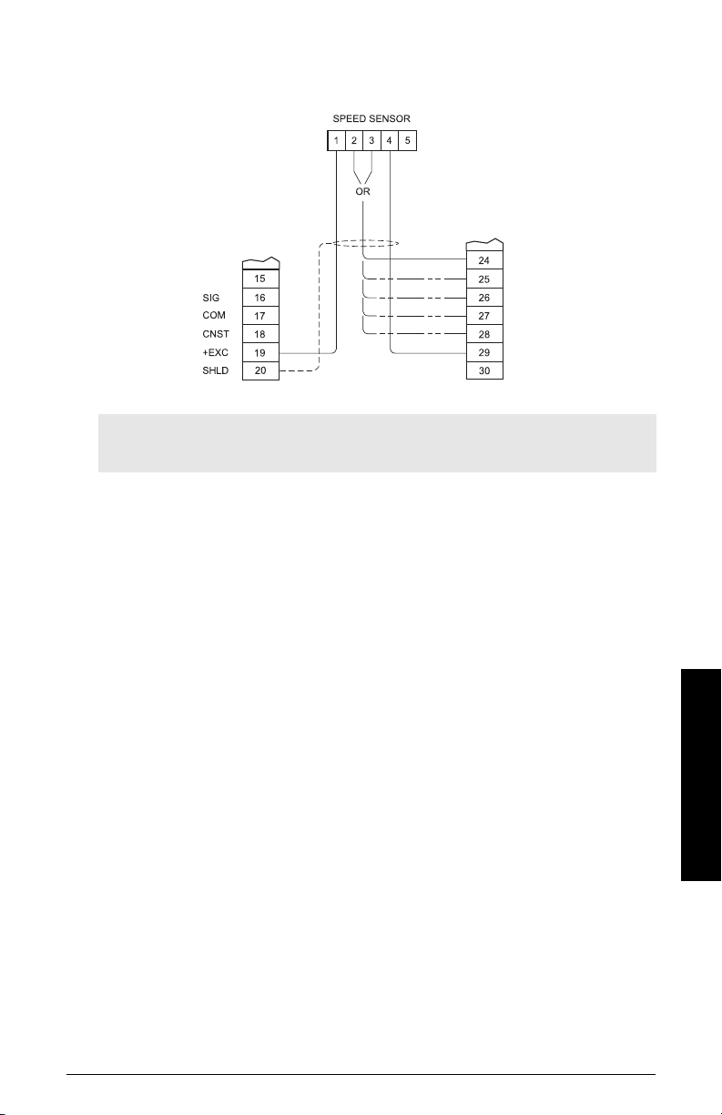
Auxiliary Speed Sensor
1)
Note: Shields are common, but not grounded to chassis. Run cable shields through
SHLD terminals and ground at BW500 only.
Connect BW500 terminal 24-28 to speed sensor terminal:
• ‘2’ for clockwise speed sensor shaft rotation
• ‘3’ for counter-clockwise speed sensor shaft rotation.
Speed sensor shaft rotation is viewed from the front cover of the speed sensor
enclosure.
Input device in the form of open collector transistor or dry contact across BW500
terminals 24-28 will also serve as a suitable speed signal.
If a speed sensor other than the models shown is supplied, consult with Siemens.
1)
Not available for BW500/L.
7ML19985DK05Milltronics BW500 and BW500/L - OPERATING INSTRUCTIONS Page 21
Installation
Page 28
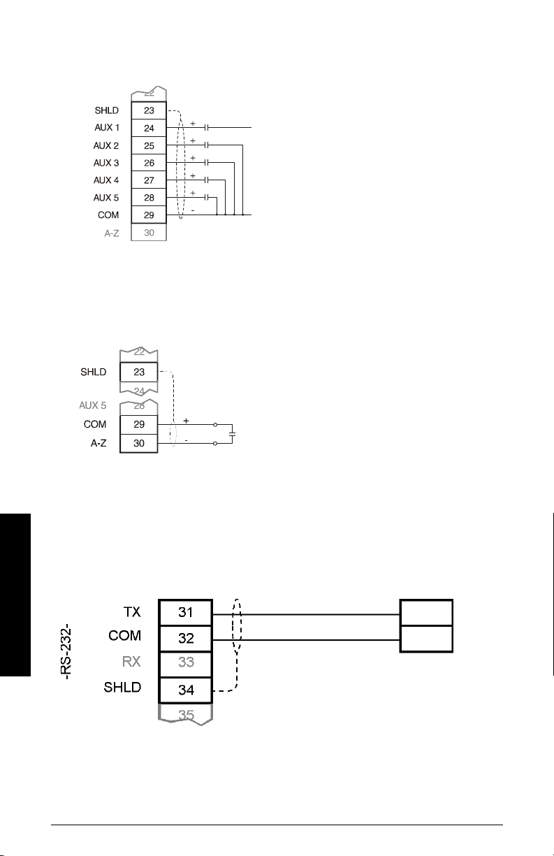
Auxiliary Inputs
receive
common
Print er
Auto Zero
Customer dry contacts, or open
collector transistor output supplied as
required
Refer to
P270
on page 122 for
programming details.
Prefeed activated dry contact
Refer to
Auto Zero
on page 47.
RS-232 Port 1
Printers
Installation
Page 22 Milltronics BW500 and BW500/L - OPERATING INSTRUCTIONS 7ML19985DK05
Page 29
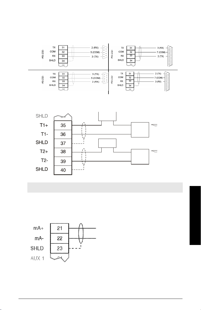
Computers and Modems
supply,
30 V max
supply,
240 V max
remote totalizer 2
remote totalizer 1
For connection to a PC compatible computer or modem, using no flow control, typical
configurations are:
DB-9 DB-25
ComputerModem
Remote Totalizer
Note: External power supply not required on all totalizer models.
mA Output 1
to customer instrumentation,
isolated mA output, 750 maximum
load
7ML19985DK05Milltronics BW500 and BW500/L - OPERATING INSTRUCTIONS Page 23
Installation
Page 30
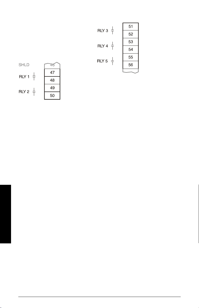
Relay Output
Relays shown in de-energized state, contacts normally open, rated 5 A at 250 V noninductive.
1)
Installation
1)
BW500/L has relay 1 and 2 only
Page 24 Milltronics BW500 and BW500/L - OPERATING INSTRUCTIONS 7ML19985DK05
Page 31
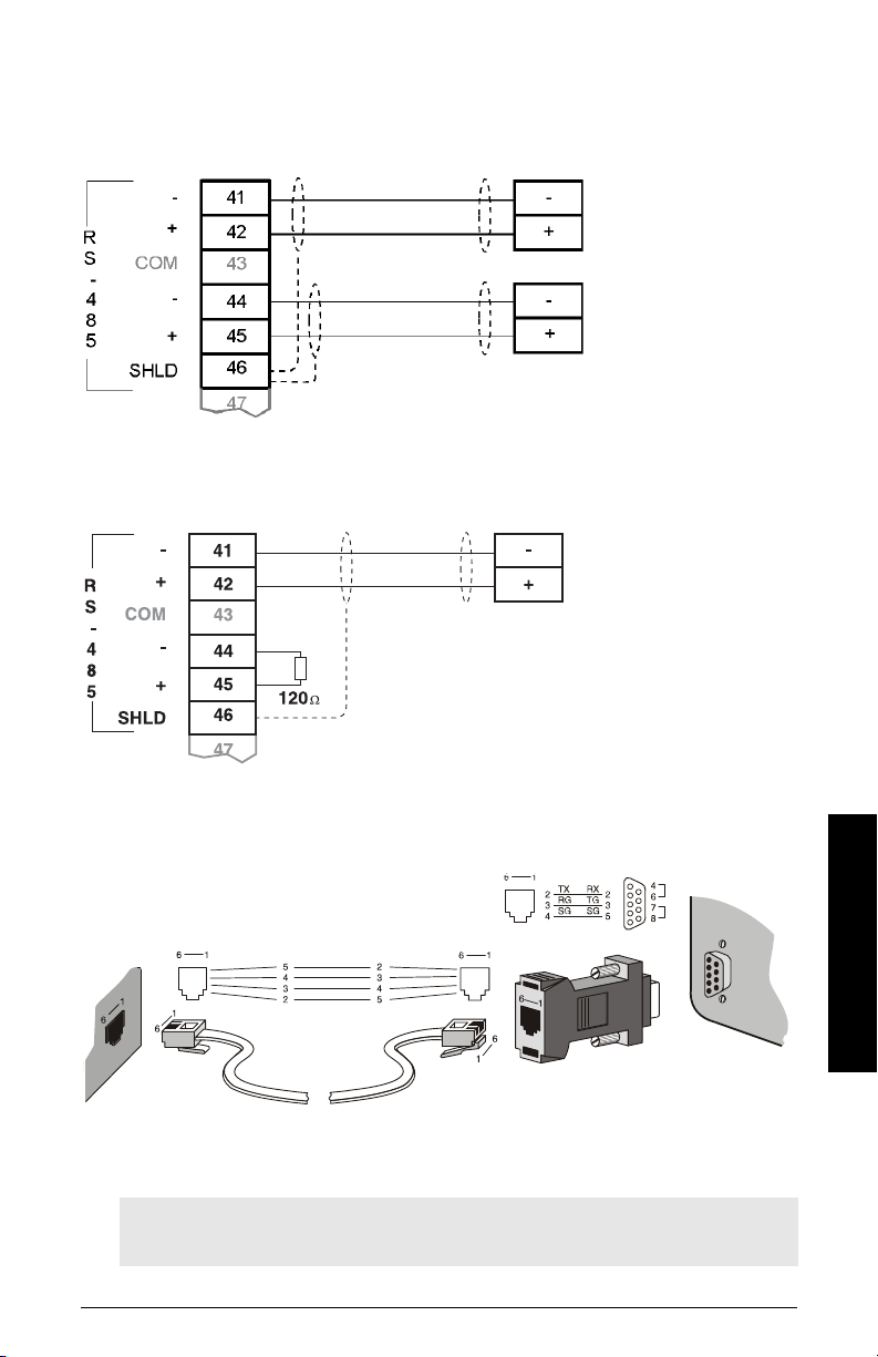
RS-485 Port 2
customer device
customer device
Daisy Chain
Termin al Device
RS-232 Port 3
Note: Jumper pins 4-6 and 7-8 when using hardware flow control. Otherwise, leave
them open.
7ML19985DK05Milltronics BW500 and BW500/L - OPERATING INSTRUCTIONS Page 25
Installation
Page 32
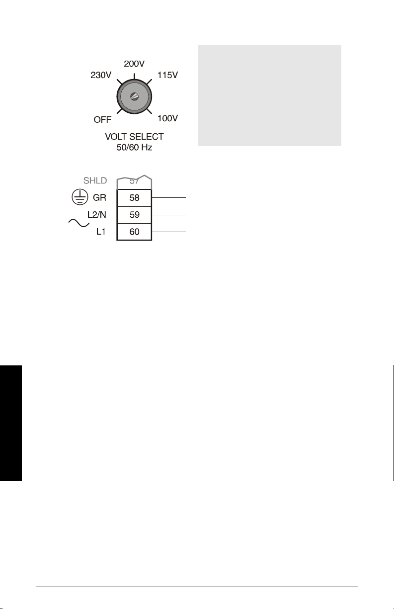
Power Connections
Note:
1. The equipment must be protected
by a 15 A fuse or a circuit breaker
in the building installation.
2. A circuit breaker or switch in the
building installation, marked as the
disconnect switch, shall be in close
proximity to the equipment and
within easy reach of the operator
100 / 115 / 200 / 230 V
50 / 60 Hz
select voltage via switch
Installation
Page 26 Milltronics BW500 and BW500/L - OPERATING INSTRUCTIONS 7ML19985DK05
Page 33
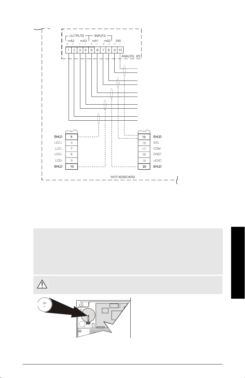
mA I/O Board connections
auxiliary supply output, isolated 24 V DC at
50 mA, short circuit protected
from customer instrumentation, isolated mA
input, 200
from customer instrumentation, isolated mA
input, 200
to customer instrumentation, isolated mA
output, 750 maximum load
to customer instrumentation, isolated mA
output, 750 maximum load
1)
Installing/replacing the back-up battery
The battery (see Specifications, page 5) should be replaced every 5 years to ensure back
up during lengthy power outages. An on board capacitor provides 20 minutes of charge to
preserve the memory while the battery is being changed.
Note:
• Do not install the memory backup battery until the BW500 and BW500/L is
installed, as it begins operation immediately.
• The unit is supplied with one battery (battery P/N PBD-2020035 (BR 2335) or use
equivalent 3V Lithium battery). Insert the battery into the holder as shown in the
following diagram before using the BW500 and BW500/L.
Disconnect power before installing or replacing the battery.
1)
Not available with BW500/L.
7ML19985DK05Milltronics BW500 and BW500/L - OPERATING INSTRUCTIONS Page 27
Installation Steps
1. Open the enclosure lid.
2. Slide the battery into the holder.
Be sure to align the + and –
terminals correctly.
3. Close and secure enclosure lid.
Installation
Page 34
Start Up
Note: For successful start up, ensure that all related system components, such as the
belt scale and speed sensor, are properly installed and connected.
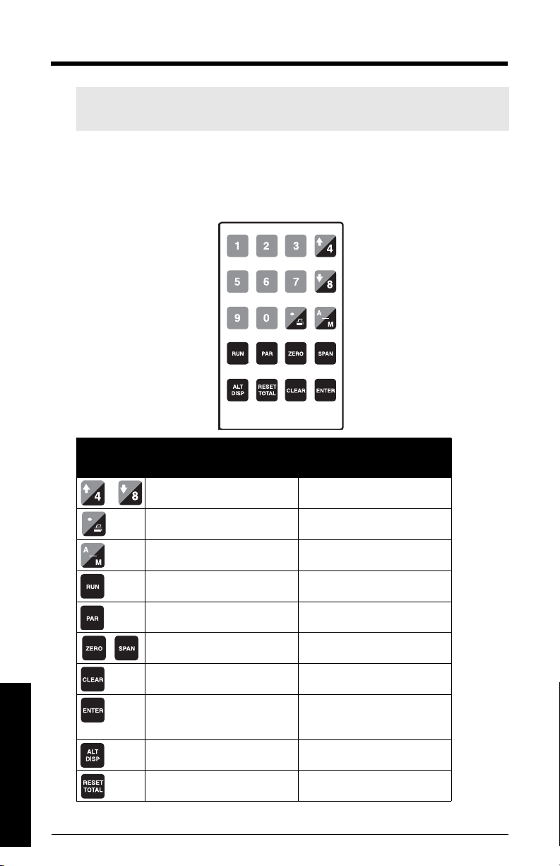
BW500 and BW500/L operates under two modes: RUN and PROGRAM. On initial powerup, the unit starts in the PROGRAM mode.
Keypad
Key Function
PROGRAM mode RUN mode
In view mode: scrolls through
parameter list
decimal key prints
changes PID local setpoint values
minus key switches PID between auto and
manual mode
opens RUN mode
opens parameter direct entry opens PROGRAM mode
initiates calibration initiates calibration
clears entry
toggles between view and edit
modes, confirms parameter values
opens RUN mode changes RUN mode display
Start Up
Page 28 Milltronics BW500 and BW500/L - OPERATING INSTRUCTIONS 7ML19985DK05
starts totalizer 1 reset sequence
Page 35
PROGRAM Mode
The PROGRAM parameters define the calibration and operation of the BW500 and
BW500/L.
In PROGRAM mode, the user can view the parameter values or edit them to suit the
application.
PROGRAM Mode Display
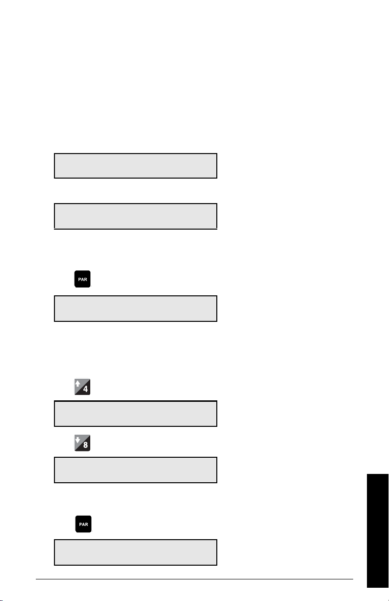
VIEW
P001 Language V
1-Eng 2-Fra 3-Deu 4-Esp
EDIT
P001 Language E
1-Eng 2-Fra 3-Deu 4-Esp 1
To enter PR OGRAM mod e:
Press
1
P001 Language V
1-Eng 2-Fra 3-Deu 4-Esp 1
To select a parameter:
Press to move up,
P002 Test Reference Selection V
1-Weight, 2-Chain, 3-Ecal 1
Press to move down.
P001 Language V
1-Eng 2-FR 3-DEU 4-ESP 1
To access a parameter directly:
Press
View/Edit Parameter
Enter Parameter Number
The default of previous parameter view is
displayed
e.g. P001 is the default parameter for initial
start up
e.g. scrolls up from P001 to P002
e.g. scrolls up from P002 to P001
Start Up
7ML19985DK05Milltronics BW500 and BW500/L - OPERATING INSTRUCTIONS Page 29
Page 36
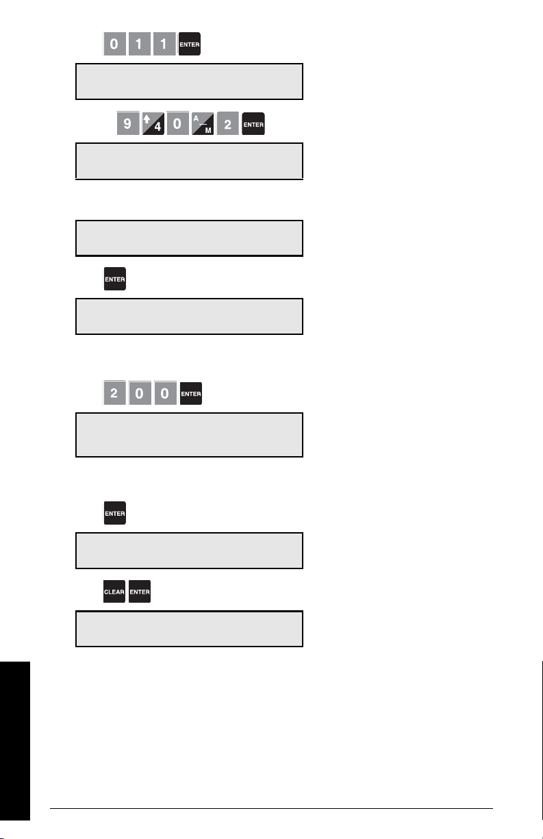
Press
in sequence.
P011 Design Rate: V
Enter Rate 100.00 kg/h
Or press
P940-2 Load Cell mV Signal Test V
mV reading for B 6.78
To change a parameter value
P011 Design Rate: V
Enter Rate 100.00 kg/h
Press
P011 Design Rate: E
Enter Rate 100.00 kg/h
Press Enter the new value
P014 Design Speed V
Enter Speed 0.08 m/S
e.g. access P011, design rate
For direct access to index parameters
e.g. access P940-2, load cell B mV signal
from the view mode
If edit mode is not enabled after pressing
ENTER, security is locked. Refer to
rity Lock (P000)
tions on disabling
For P001 to P017, ENTER effects the
change and scrolls to the next required
parameter.
on page 111 for instruc-
Secu-
To reset a parameter value
Press
P011 Design Rate: E
Enter Rate 100.00 kg/h
Press
P011 Design Rate: V
Enter Rate 0.00 kg/h
Start Up
Page 30 Milltronics BW500 and BW500/L - OPERATING INSTRUCTIONS 7ML19985DK05
From the edit mode
Value is reset to factory value.
e.g. 0.00 kg/h
Page 37
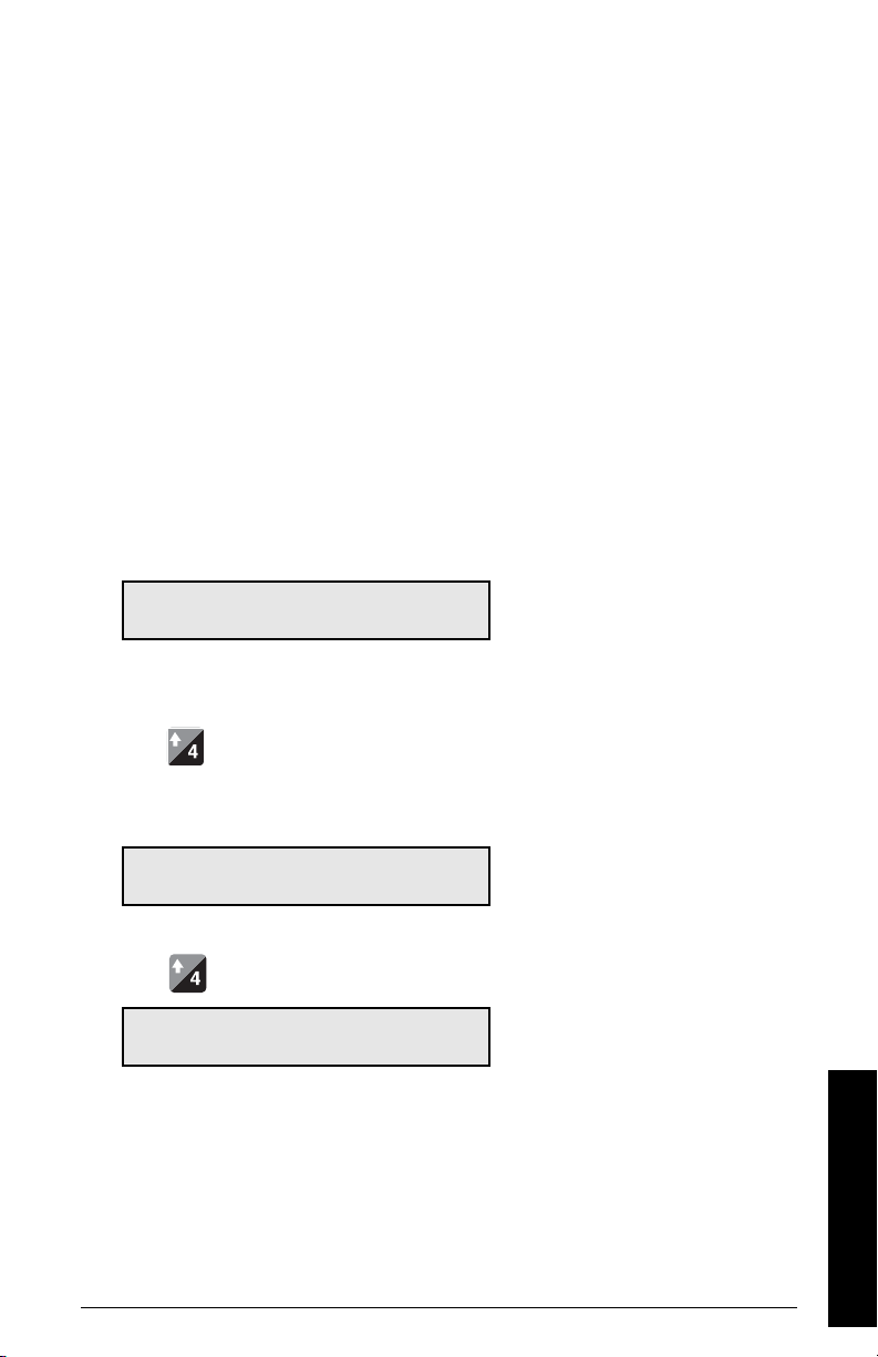
RUN Mode
To operate BW500 and BW500/L in the RUN mode, the unit must undergo an initial
programming to set up the base operating parameters.
Attempting to enter the RUN mode without satisfying the program requirements forces
the program routine to the first missing item.
Initial Start Up
Initial start up of BW500 and BW500/L consists of several stages, and assumes that the
physical and electrical installation of the belt scale and speed sensor, if used, is complete:
• power up
• programming
• load cell balancing
• zero and span calibration
Power Up
Upon initial power up, BW500 and BW500/L displays:
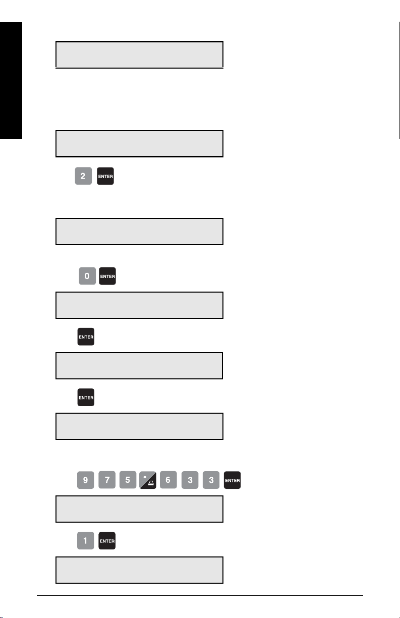
P001 Language V
1-Eng 2-Fra 3-Deu 4-Esp 1
The initial display prompts the user to
select the preferred language.
Programming
Press
BW500 and BW500/L then scrolls sequentially through the start up program as
parameters P001 through P017 are addressed.
P002 Test Reference Selection V
Select 1-Weight, 2-Chain, 3-Ecal 1
Press
P003 Number of Load Cells V
Enter Number of Load Cells 2
e.g. Accept ’weight’ (supplied with scale)
as the test reference.
e.g. Accept ’2’ as the number of load cells.
Start Up
7ML19985DK05Milltronics BW500 and BW500/L - OPERATING INSTRUCTIONS Page 31
Page 38
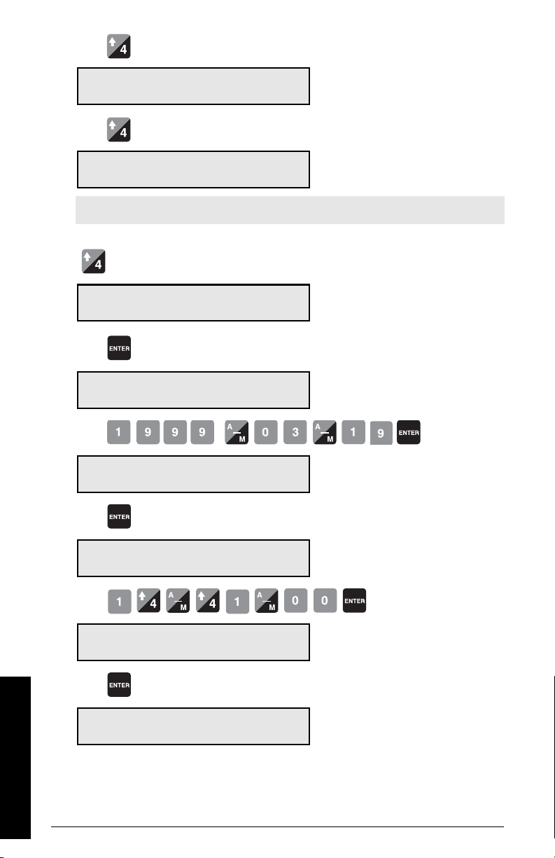
Press
P004 Rate Measurement System V
Select 1-Imperial, 2-Metric 2
Press
P005 Design Rate Units: V
Select: 1-t/h, 2-kg/h, 3-kg/min 1
Note: t/h equals metric tonnes per hour
Press
1)
P008 Date: V
Enter YYYY-MM-DD 1999-03-19
Press
P008 Date: E
Enter YYYY-MM-DD 1999-03-19
Press
P009 Time: V
Enter HH-MM-SS 00-00-00
e.g. Accept ’2’ for measurements in metric.
e.g. Accept ’1’ for units in t/h
default date
e.g. enter current date of March 19, 1999
factory set time 24 hour clock
Press
P009 Time: E
e.g. enter current time of 14:41
Enter HH-MM-SS 00-00-00
Press
P011 Design Rate: V
factory design rate
Enter Rate 0.00 t/h
Press
P011 Design Rate: E
Enter Rate 0.00 t/h
e.g. rate of 100 t/h
Start Up
1)
Not applicable for the BW500/L
Page 32 Milltronics BW500 and BW500/L - OPERATING INSTRUCTIONS 7ML19985DK05
Page 39
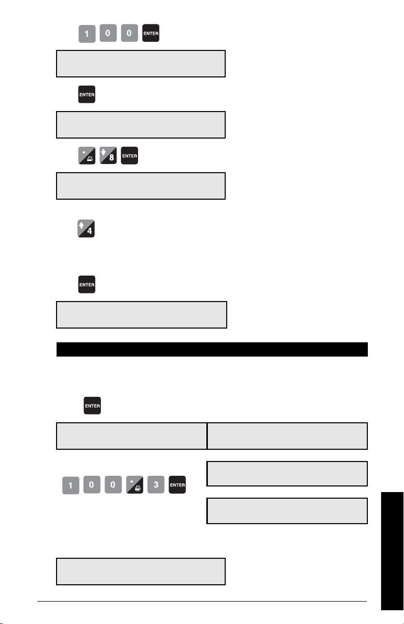
Press
P014 Design Speed V
factory design speed
Enter Speed 0.00 m/s
Press
P014 Design Speed E
Enter Speed 0.00 m/s
Press
e.g.speed of 0.8 m/s
P015-01 Speed Constant V
Pulses/m 0.0000
If the speed input is configured for constant speed, display value reads ‘Jumpered’
press to advance.
If the speed input is connected to a speed sensor, pressing enter at P015 invokes P690 for
data entry.
Press
P690-01 Speed Constant Entry E
1-Calculated, 2-Sensor Data 1
Select: 1 - Calculated Select: 2 - Sensor Data
The program returns to P015. Calculate the
value per Parameter P690.
Press
The program advances through parameters P691
and P692 prompting entry from the sensor nameplate. From this data, the speed constant is calculated and automatically entered into P015.
P015-01 Speed Constant
Pulses/m 0.0000 0.00 mm
Press
e.g. speed constant of 100.3 pulses
per meter
This value is calculated. For manual or automatic calculation, refer to
P691-01 Step 1: Drive Pully Diameter
E
P692-01 Step 2: Pulses per sensor Rev.
Enter Pulses 0.00
P015-01 Speed Constant
Pulses/m 0.0000
P690
on page 140.
V
V
V
To program Differential Speed (P015-02), follow steps above for P015-01.
P016 Belt Length V
Enter Length 0.0 00 m
factory set length
7ML19985DK05Milltronics BW500 and BW500/L - OPERATING INSTRUCTIONS Page 33
Start Up
Page 40
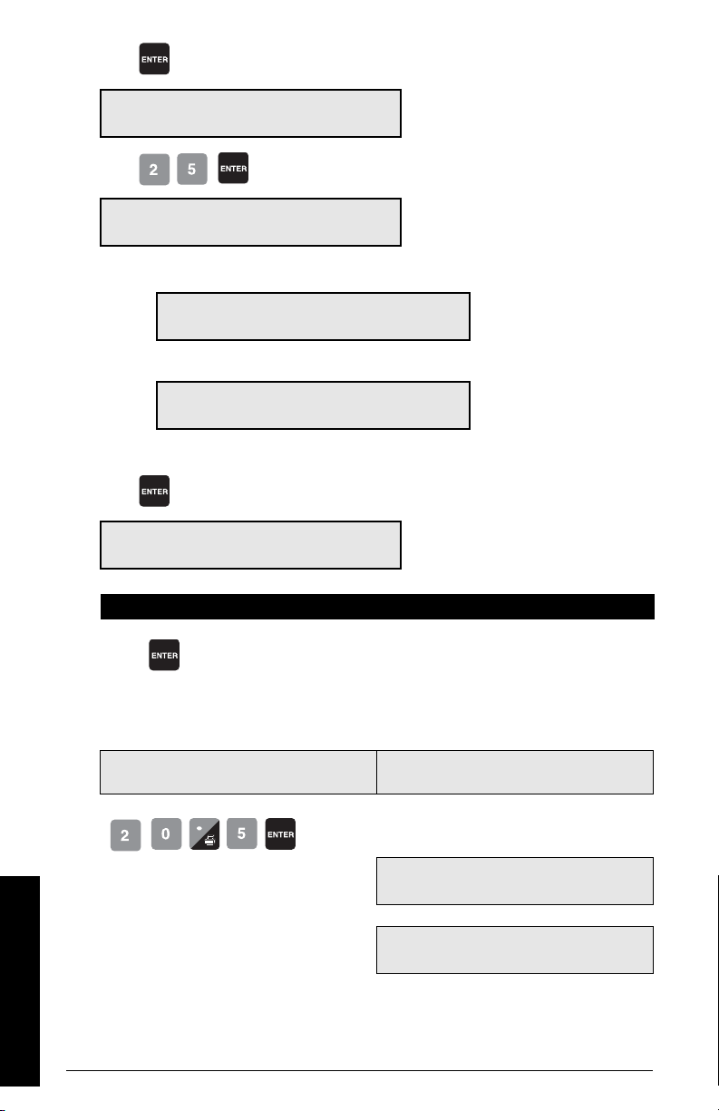
Press
P016 Belt Length E
Enter Length 0.0 00 m
e.g. belt length of 25 m
Press
P017 Test Load: Weight MS 1 V
Enter test load 0.00 kg/m
If P002 Test Load Reference had been set for 2-Chain, the display would read:
P017 Test Load: Chain MS 1 V
Enter test load 0.00 kg/m
or, if 3-ECal refer to ECal parameters (P693 - P699 on page 141)
P017 Test Load: ECal MS 1 V
Enter test load 0.00 kg/m
or, if P002 is set to 1-Weight, pressing enter at P017 invokes P680 for data entry.
Press
P680 Test Load: Weight MS 1 V
1-Enter Value, 2-Enter Data 0
Select: 1 - Enter Value Select: 2 - Enter Data
The program returns to P017.
Press
P017 Test Load: Weight MS 1
Enter test load 00.00 0.00 kg
Press
The program advances through parameters
P681 and P682 prompting entry of the total
mass of all the test weights used for SPAN calibration and the average measured idler space
before and after the scale. From this data the
test load is calculated and automatically
entered into P017
E
P681 Step 1: Total Mass of Test
Weigh ts
Units are selected in P004: metric, imperial.
V
e.g. test load of 20.5 kg/m
P682 Step 2: Average Idler Space
P017 Test Load: Weight MS 1
Enter test load
This value is calculated. For manual or automatic calculation, refer to P680 on page 139.
Start Up
The test load value should be less than the design load (P952). If not, contact Siemens.
Page 34 Milltronics BW500 and BW500/L - OPERATING INSTRUCTIONS 7ML19985DK05
V
0.00 m
V
00.00
Page 41
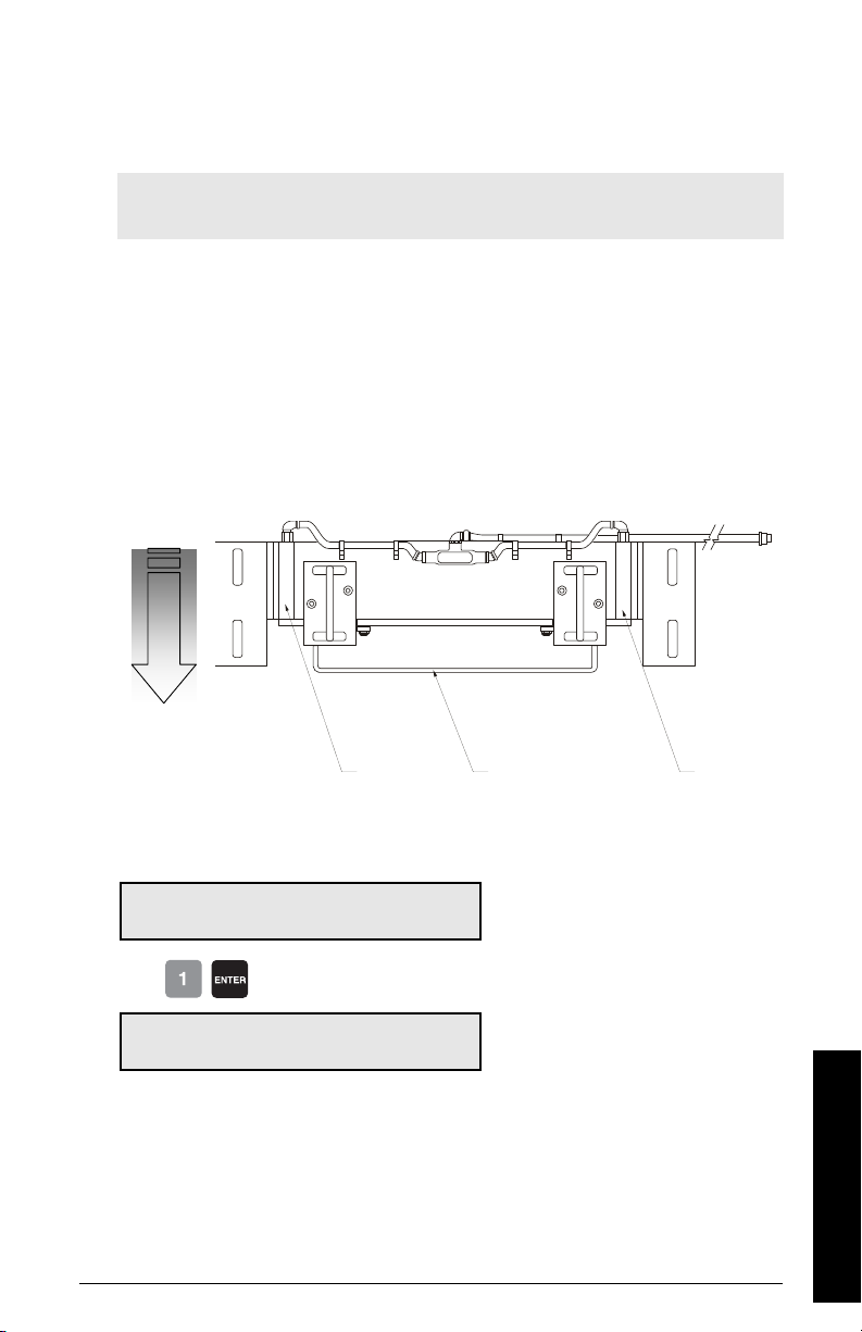
The initial programming requirements are now satisfied. To ensure proper entry of all
Belt
travel
load cell
’B’
test weight bar
load cell
’A’
critical parameter values, return to P002 and review parameters through to P017.
Load Cell Balancing
Note: Load cell balancing is not required if the selected test reference is ECal (P002 =
3). In the case of ECal, the load cells are balanced by the ECal procedure.
If you are operating a two or four1) load cell belt scale, it is recommended that the load
cells be balanced electronically prior to initial programming and calibration, or after either
or both load cells have been reinstalled or replaced.
Unbalanced load cells can adversely affect the performance of your belt conveyor
weighing system.
With the conveyor stopped and locked out, lift the belt off the weighing idlers.
Typical two load cell belt scale
Access P295
P295 Load Cell Balancing: E
Select: 1-A&B, 2-C&D 0
Press
Load Cell Balancing A & B
Place weight at cell B and press ENTER
1)
For six load cell configurations contact your local Siemens representative.
7ML19985DK05Milltronics BW500 and BW500/L - OPERATING INSTRUCTIONS Page 35
option ’2’ enabled only if P0 03, number of
load cells is 4
Start Up
Page 42
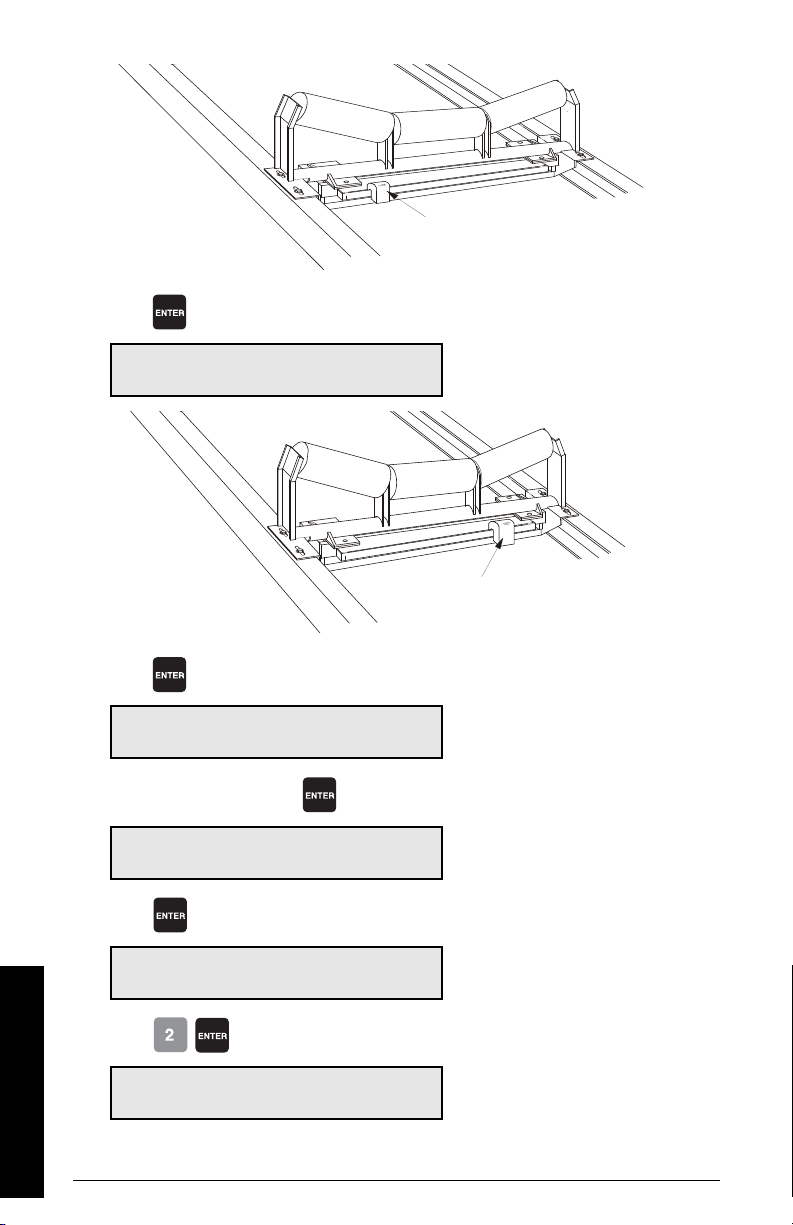
Press
test weight
’A’
’B’
test weight
’A’
’B’
Load Cell Balancing A & B
Place weight at cell A and press ENTER
Press
Load Cell Balancing A & B
Load cells are now balanced.
Balancing the load cells requires a subsequent zero and span calibration
if four load cell scale, press to continue
P295 Load Cell Balancing: V
Select: 1-A&B, 2-C&D 1
Press
P295 Load Cell Balancing: E
Select: 1-A&B, 2-C&D 1
Press
Load Cell Balancing C & D
Start Up
Place weight at cell D and press ENTER.
Page 36 Milltronics BW500 and BW500/L - OPERATING INSTRUCTIONS 7ML19985DK05
Page 43
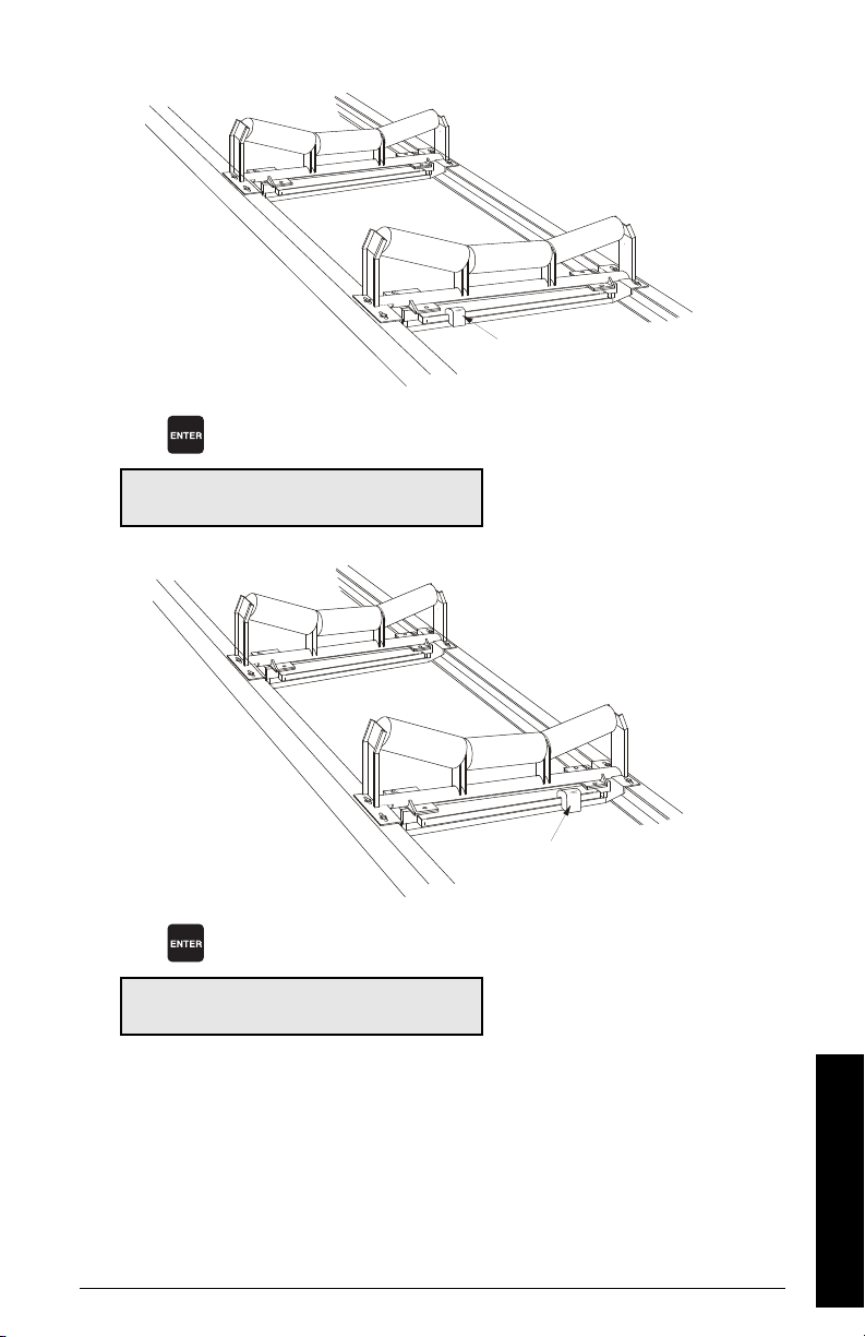
Press
test weight
’A’
’B’
’D’
’C’
test weight
’B’
’A’
’C’
’D’
Load Cell Balancing C & D
Place weight at cell C and press ENTER.
Press
Load Cell Balancing C & D
Load cells are now balanced.
7ML19985DK05Milltronics BW500 and BW500/L - OPERATING INSTRUCTIONS Page 37
Balancing the load cells requires a subsequent zero and span recalibration
Start Up
Page 44
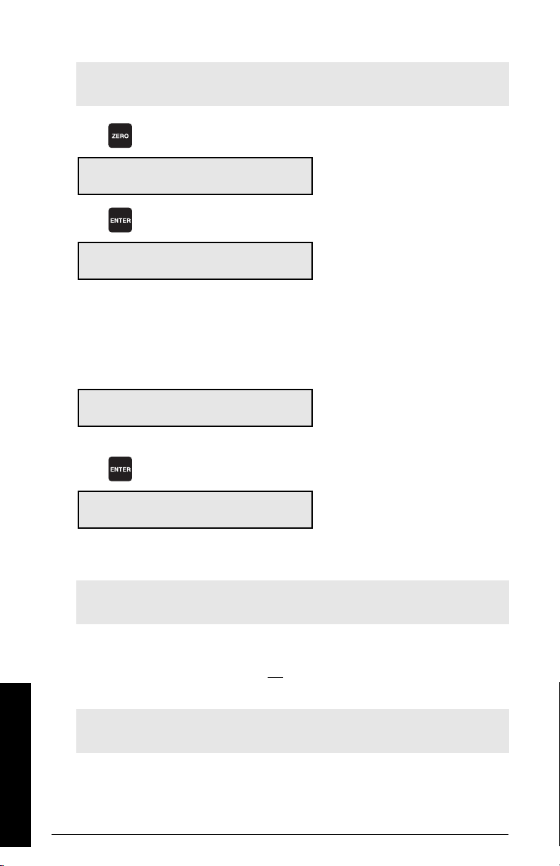
Zero Calibration
Note: To obtain an accurate and successful calibration, ensure that the required
criteria are met. Refer to
Press
Calibration Criteria
on page 155.
Zero Calibration: Current Zero 0
Clear belt. Press ENTER to Start
Press
Initial Zero Calibration. In progress %
Current Reading: #####
The duration of the Zero calibration is dependent on speed (P014), length (P016), and
revolutions (P360) of the belt.
Calibration Complete. Deviation 0.00
Press ENTER to accept value: 551205
Press
Zero Calibration. Current Zero 551205
Clear belt. Press ENTER to Start
Accepting the Zero returns to start of Zero. A new Zero can be performed, or continue to
Span.
the current zero count
the zero count being calculated while calibration is in progress
the deviation from previous zero. For an
initial zero there is no previous zero; hence
the deviation is 0.
e.g. the new zero count, if accepted
Note: The moisture meter is ignored during calibration. If inclinometer is used, then
calibration is adjusted based on incline angle.
Span Calibration
When performing a Span Calibration where the test reference is ECal (P002 = 3), the
supplied test weight or test chain must not
be applied, and the conveyor must be run
empty.
Note: To obtain an accurate and successful calibration, ensure that the required
criteria are met. Refer to
With the conveyor stopped and locked out, apply the test weight or chain to the scale as
Start Up
instructed in the associate manuals; then start the conveyor.
Page 38 Milltronics BW500 and BW500/L - OPERATING INSTRUCTIONS 7ML19985DK05
Calibration Criteria
on page 155.
Page 45
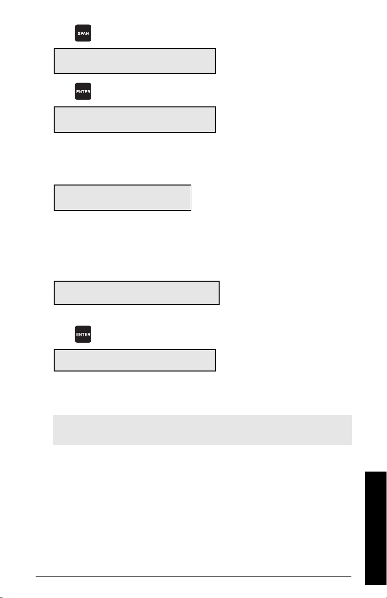
Press
Span Calibration Current Span 0
the current span count
Setup test Press ENTER to Start
Press
Initial Span Calibration in progress %
Current Reading ####
the span count being calculated while calibration is in progress
The duration of the Span calibration is dependent on speed (P014), length (P016), and
revolutions (P360) of the belt.
if
Span Count Too Low
Press CLEAR to continue
Calibration Complete Deviation 0.00
Press ENTER to accept value: 36790
signal from load cell too low, ensure proper test
weight or chain is applied during calibration
check for proper load cell wiring and ensure shipping brackets have been removed.
the deviation from the previous span.
For an initial span, there is no previous
span count; hence the deviation is 0.
e.g. the new span count,
if accepted.
Press
Span Calibration. Current Span 36790
Setup test. Press ENTER to Start
e.g. the current span
count
Accepting the Span returns to start of Span. A new Span can be performed, or enter RUN
mode. If calibrating with a test weight or test chain, remove it from the scale and store in
a secure place before returning to RUN mode.
Note: The moisture meter is ignored during calibration. If the Inclinometer is used,
then calibration is adjusted based on incline angle.
7ML19985DK05Milltronics BW500 and BW500/L - OPERATING INSTRUCTIONS Page 39
Start Up
Page 46

RUN Mode
Proper programming and successful zero and span calibration allow entry into the RUN
mode. Otherwise, entry is denied and the first missing item of programming or calibration
is displayed.
Press
Rate 0.00 t/h
Total 1 0.00 t
Once the initial programming is complete and the BW500 and BW500/L is operating in the
RUN mode, you may now put the belt conveyor into normal service. The BW500 is
functioning under its initial program and calibration, reporting rate of material flow and
totalizing.
e.g. if there is no material on the belt and
the conveyor is running. The current rate is
0 and no material has been totalized.
Start Up
Page 40 Milltronics BW500 and BW500/L - OPERATING INSTRUCTIONS 7ML19985DK05
Page 47
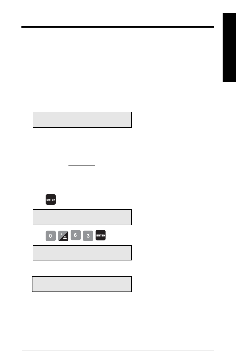
Recalibration
Belt Speed Compensation
To achieve optimum accuracy in the rate computation, the belt speed displayed must
equal that of the actual belt speed. As the speeds are likely to differ, a belt speed
compensation should be performed.
Run the conveyor with the belt empty.
View the belt speed.
Access P018
Recalibration
P018 Speed Adjust V
Enter New Speed 0.60
Stop the conveyor and measure a length of the belt; marking the forward end (start time)
and the back end (stop time). Use the belt scale as the stationary reference.
Run the belt and measure the time for the belt length to pass over the scale.
speed =
Refer to the
changing values.
Press
P018 Speed Adjust E
Enter New Speed 0.60
Press
P015 Speed Constant V
Pulses/m 97.5169
if
P014 Design Speed V
Enter Speed 0.63 m/s
belt length
time
Start Up
section on page 28 for instructions on parameter selection and
m/s or ft/min.
e.g. current speed of 0.6 m/s
e.g. current speed of 0.6 m/s
e.g. enter correct speed of 0.63 m/s
speed sensor constant, adjust for P015
for constant speed (jumper), adjusts P014
The displayed speed (used in the rate computation) now equals the actual speed.
7ML19985DK05Milltronics BW500 and BW500/L - OPERATING INSTRUCTIONS Page 41
Page 48

Material Tests
Perform material tests to verify the accuracy of the span calibration and compensate for
material flow. If the material tests indicate a repeatable deviation exists, perform a
manual span adjust (P019). This procedure automatically alters the span calibration and
adjusts the test load (P017) value, yielding more accurate span recalibrations.
Recalibration
If the span adjust value is within the accuracy requirements of the weighing system, the
material test was successful. Resume normal operation.
If the span adjust value is not acceptable, repeat the material test to verify repeatability. If
the result of the second material test differs considerably, consult Siemens or contact
your local Siemens representative.
If the span adjust values are significant and repeatable, perform a manual span adjust.
Note: Test weights are NOT used during material tests.
There are two methods of executing the manual span adjust:
% Change
and
Te st
•
% Change
material and the weight reported by the BW500 and BW500/L is calculated and
entered into P019 as % change.
Material Test:
•
P019
The method of execution is a matter of preference or convenience, and either way yields
the same result.
: based on the material test, the difference between the actual weight of
based on material test, the actual weight of material is entered into
% Change
To run a %Change material test:
1. Run the belt empty
2. Perform a zero calibration
3. Put the BW500 and BW500/L into RUN mode
4. Record the BW500 and BW500/L total as the start value _ _ _ _ _ _
5. Run material at a minimum of 50% of design rate over the belt scale for a minimum
of 5 minutes
6. Stop the material feed and run the conveyor empty
7. Record the BW500 and BW500/L total as the stop value _ _ _ _ _ _ _
8. Subtract the start value from the stop value to determine the BW500 and BW500/L
total
9. Weigh the material sample if not already known
BW500 and BW500/L total = _ _ _ _ _ _ _
material sample weight = _ _ _ _ _ _ _
_
Material
Calculate the span adjust value:
Page 42 Milltronics BW500 and BW500/L - OPERATING INSTRUCTIONS 7ML19985DK05
Page 49
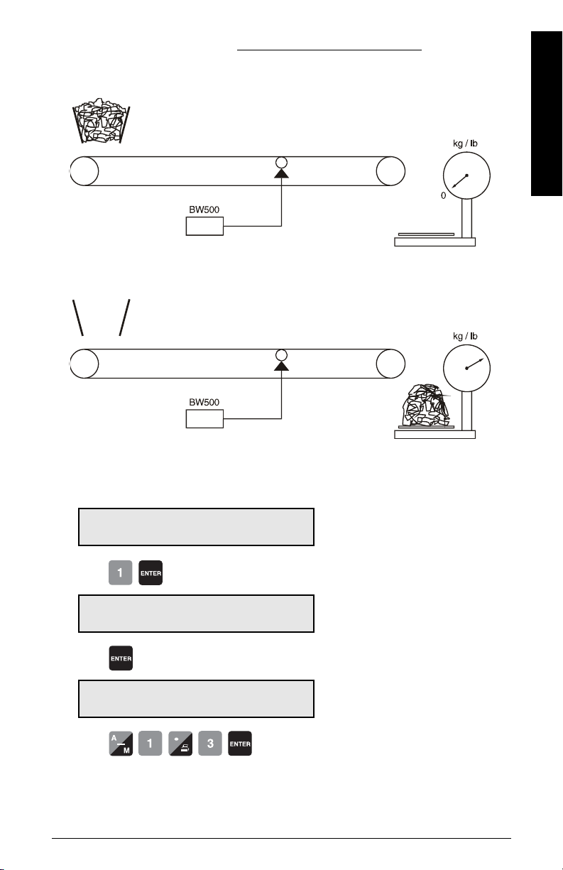
% span adjust =
stop total
start total
scale
scale
(BW500 – material sample weight) x 100
material sample weight
Recalibration
Access P019 and enter EDIT mode
P019 Manual Span Adjust E
Select 1-% Change 2-Material Test 0
Press
P598 Span Adjust Percentage V
Enter Calculated +/- error 0.00
Press
P598 Span Adjust Percentage E
Enter Calculated +/- error 0.00
Press
7ML19985DK05Milltronics BW500 and BW500/L - OPERATING INSTRUCTIONS Page 43
Page 50
if % change is negative, remember to enter the minus sign, e.g. -1.3
Material Test
Recalibration
Access P019 and enter EDIT mode
Press
Press
Press
P017 Test Load Weight: MS1 V
Enter Test Load 56.78
P019 Manual Span Adjust E
Select 1-% Change 2-Material Test 0
Material Test
Add to Totalizer 0-No, 1-Yes
Material Test
Press ENTER to start
e.g. the new test load value is displayed
if yes, the weight of the material test will
be added to the totalizer, if no, material is
added to test totalizer (4) only.
e.g. do not add weight of material test to
totalizer
Material Test tonnes
Press ENTER key to stop #.### t
the totalizer reading as the material test is
run
Press
Material Test 964.032 t
Enter actual amount tonnes
Press
Material Test Deviation -1.19
Accept 0-No, 1-Yes
Press
P017 Test Load Weight: MS1 V
e.g. the weight totalized by the belt scale
and BW500 and BW500/L
e.g. 975.633 kg is the actual weight of the
material test
e.g. the calculated deviation is displayed
as a % of the actual weight
e.g. the new test load value is displayed.
Enter Test Load 56.78
Page 44 Milltronics BW500 and BW500/L - OPERATING INSTRUCTIONS 7ML19985DK05
Page 51
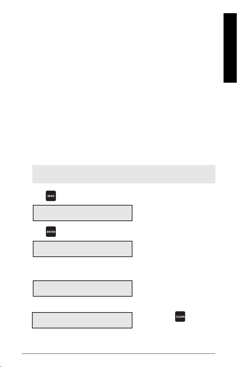
Verify the results of the span adjust by material test or return to normal operation.
Design Changes
Where parameters have been changed with a resultant impact on the calibration, they do
not take effect until a recalibration is done.
If significant changes have been made, an initial zero (P377) and/or initial span (P388)
may be required (see page 128).
Recalibration
To maintain the accuracy of the weighing system, periodic zero and span recalibration is
required. Recalibration requirements are highly dependent upon the severity of the
application. Perform frequent checks initially, then as time and experience dictate, the
frequency of these checks may be reduced. Record deviations for reference.
The displayed deviations are referenced to the previous zero or span calibration.
Deviations are continuously tallied for successive zero and span calibrations, and when
exceed their limit, indicate an error message that the deviation or calibration is out of
range.
Routine Zero
Note: To obtain an accurate and successful calibration, ensure that the required
criteria are met. Refer to
Press
Calibration Criteria
on page 155.
Recalibration
Zero Calibration. Current Zero. 551205
Clear belt. Press ENTER to start
Press
Zero Calibration in progress %
Current Reading: 0.01 kg/m
Calibration complete. Deviation 0.02
Press ENTER to accept value 551418
if
Calibration is out of range
Deviation report: 403.37
This indicates that the mechanical system is errant. P377, initial zero, should be used
judiciously and only after a thorough mechanical investigation.
7ML19985DK05Milltronics BW500 and BW500/L - OPERATING INSTRUCTIONS Page 45
e.g. the current zero count
e.g. the load reported while calibration is
in progress
e.g. the calculated deviation in % of full
span
e.g. the new zero count, if accepted
if unacceptable, press to restart
Page 52
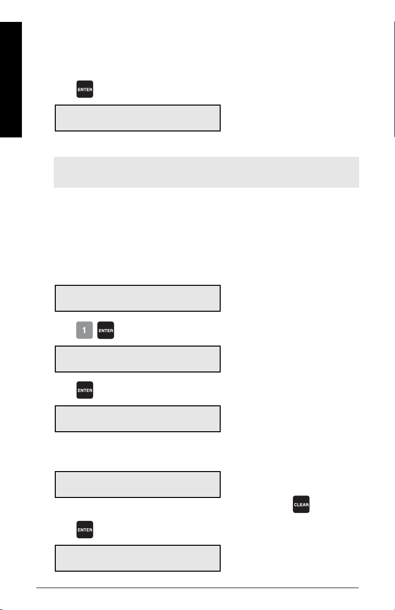
Recalibration
Initial Zero
The cause of the increased deviation must be found and rectified. A zero recalibration as
previously described can then be retried.
If the operator deems this deviation to be acceptable, set P377 to 1 to invoke an initial
zero calibration. Further deviation limits are now based on this new initial zero.
Press
Zero Calibration. Current Zero 551418
Clear belt. Press ENTER to start
e.g. zero calibration is accepted and displayed as the current zero
Note: This is the end of zero calibration. Proceed with zero, or span recalibration, or
return to RUN.
Perform an initial zero if necessary when calibration is out of range message is shown.
During this step the progress of the process will be shown on the display with a progress
indicator in %.
Access P377 and enter EDIT mode
P377 Initial Zero E
Enter 1 to start initial Zero 0
Press
Zero Calibration. Current Zero 530560
e.g. the current zero
Clear belt. Press ENTER to start
Press
Initial Zero Calibration in progress %
Current Reading: #####
Calibration complete. Deviation 0.00
Press ENTER to accept value 551413
the zero count being calculated while calibration is in progress
e.g. the deviation from the previous zero
e.g. the new zero count if accepted
if unacceptable, press to restart
Press
Zero Calibration. Current Zero 551413
e.g. the current zero count
Clear belt. Press ENTER to start
Page 46 Milltronics BW500 and BW500/L - OPERATING INSTRUCTIONS 7ML19985DK05
Page 53
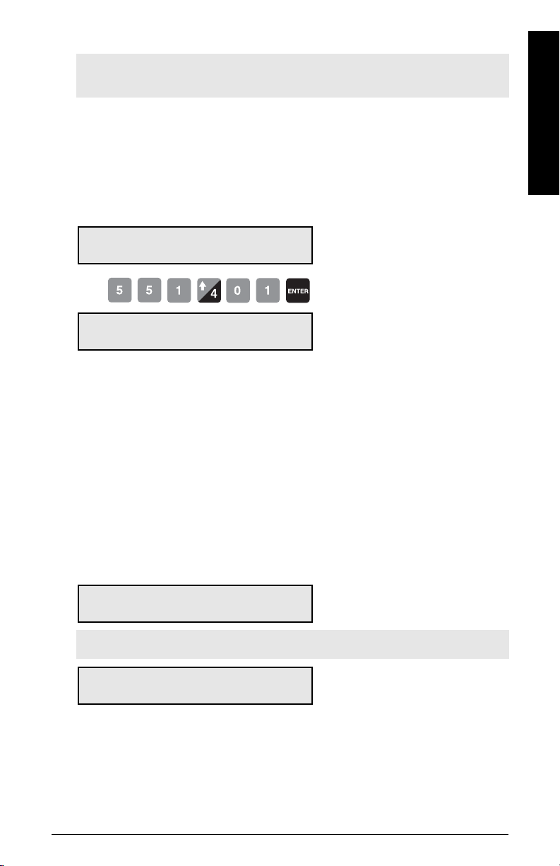
Note: This is the end of zero calibration. Proceed with span recalibration or return to
RUN.
Direct Zero
Use direct zero entry (P367) when replacing software or hardware, if it is not convenient
to perform an initial zero. A record of the last valid zero count is required.
Access P367 and enter EDIT mode
P367 Direct Zero Entry E
Enter Zero Count 0
Recalibration
Press
Zero Calibration. Current Zero V
Enter Zero Count 551401
e.g. the last valid zero count
Auto Zero
The Auto Zero function is useful in outdoor applications where there are fluctuations in
temperature, causing the zero to change throughout the day.
Auto Zero provides automatic zero calibration in the RUN mode under the following
conditions:
• the auto zero input (terminals 29/30) is in a closed state; jumper or remote contact
• the load on the belt is within the programmed percentage (P371) based on the
design load (P952)
• the terminal and load status coincide for at least one belt revolution
The rate display is interrupted by the Auto Zero routine
Rate 0.00 t/h
Total 1: 0.00 tonnes AZ
Note: t/h equals metric tonnes per hour
Calibration Complete. Deviation 0.0
Auto-Zero value 551410
1)
.
(AZ flashes on and off)
e.g. typical zero and deviation values
The duration of the auto zero is one or more belt revolutions (P360). If either condition is
interrupted during that period, the auto zero is aborted and the RUN display is resumed.
After one belt revolution, another auto zero will be attempted if the input and load
conditions are met.
1)
Set Parameter P371 to a value from 1 to 10%, default is 2%. See “P371 Auto Zero
Initiation Upper Limit” on page 128.
7ML19985DK05Milltronics BW500 and BW500/L - OPERATING INSTRUCTIONS Page 47
Page 54
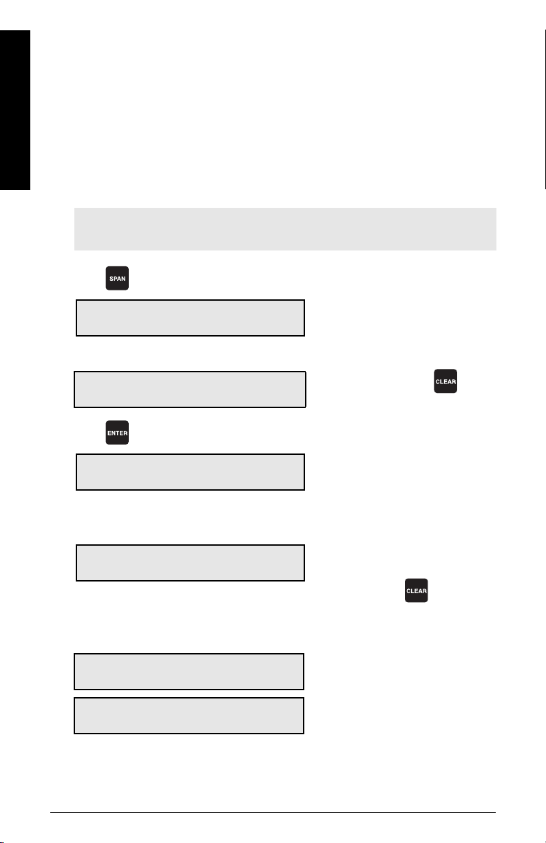
Recalibration
If the resulting zero deviation is less than an accumulated 2% from the last operator
initiated zero, the auto zero is accepted.
If the deviation is greater than an accumulated 2%, an error message is displayed. The
error message is cleared after five seconds, however if a relay is programmed for
diagnostics, it remains in alarm so long as the Auto Zero conditions are being met.
If material feed resumes during an auto zero function and is greater than the maximum
load on the belt (P371), the totalizing function is maintained.
Routine Span
1)
Note: To obtain an accurate and successful calibration, ensure that the required
criteria are met. Refer to
Press
Span Calibration. Current Span 41285
Setup test. Press ENTER to start
if
Zero should be done prior to Span
Setup test. Press ENTER to start.
Press
Span Calibration in progress %
Current Reading: 55.56 kg/m
Calibration complete. Deviation 0.03
Press ENTER to accept value 41440
Calibration Criteria
on page 155.
e.g. the current span count
do a zero calibration or press
the load reported while calibration is
in progress.
e.g. the deviation from the previous span
e.g. the new span count, if accepted
if unacceptable, press to restart
if
Span Count too Low.
Press CLEAR to continue.
Calibration aborted
signal from load cell too low: ensure shipping brackets are removed and proper test
weight or chain is applied during span
e.g. belt speed is <10% of design (P014)
Belt speed is too low:
1)
During this step the progress of the process will be shown on the display with a
progress indicator in %
Page 48 Milltronics BW500 and BW500/L - OPERATING INSTRUCTIONS 7ML19985DK05
Page 55
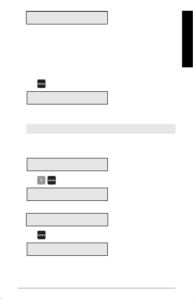
Calibration is out of range
Deviation Error: XX.XX
This indicates that the mechanical system is errant. The use of P388, initial span, should
be used judiciously and only after a thorough mechanical investigation has been
exercised.
Find and rectify the cause of the increased or decreased deviation. Then re-try a span
recalibration.
If this deviation is still unacceptable, set P388 to 1 to invoke an initial span calibration.
Further deviation limits are now based on this new initial span.
Press
Recalibration
Span Calibration. Current Span 41440
Setup test. Press ENTER to start
Initial Span
1)
e.g. span calibration is accepted and
displayed as the current value
Note: Perform an initial span when a calibration out of range message appears.
A zero calibration should be performed prior to performing a span calibration.
Access P388 and enter EDIT mode
P388-01 Initial Span E
Enter 1 to start Initial Span 0
Press
Span Calibration. Current Span 41440
Setup test. Press ENTER to start
If
Zero should be done prior to Span
Setup test. Press ENTER to start
Press
e.g. the current span count
do a zero calibration or clear
Initial Span Calibration in progress
Current Reading: #####
1)
During this step the progress of the process will be shown on the display with a
progress indicator in %.
7ML19985DK05Milltronics BW500 and BW500/L - OPERATING INSTRUCTIONS Page 49
the span count being calculated
while calibration is in progress
Page 56
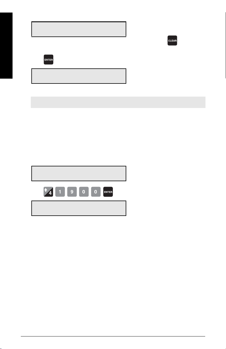
Calibration complete. Deviation 0.00
Press ENTER to accept value 41900
the deviation is reset
e.g. the new span value if accepted
if unacceptable, press to restart
Recalibration
Direct Span
Press
Span Calibration. Current Span 41900
Setup test. Press ENTER to start
e.g. the current span count
Note: End of span calibration. Remove the test weight and return to RUN.
Direct span entry (P368) is intended for use when replacing software or hardware, and
when it is not convenient to perform an initial span. A record of the last valid span count
is required.
Access P368 and enter EDIT mode
P368-01 Direct Span Entry E
Enter Span Count 0
Press
P368-01 Direct Span Entry V
Enter Span Count 41900
e.g. the last valid span count
Multispan
The BW500 offers a multispan function, which allows the BW500 to be calibrated for up
to eight different feed conditions that would produce varying load characteristics.
Different feed conditions are typically related to the running of different materials or
multiple feed locations. The varying load characteristic often has a bearing on the belt
tension, and is observed especially when in close proximity to the scale. To
accommodate such scale applications, a span correction can be made by selecting and
applying the appropriate span.
Since every material has its own unique physical properties, and may load the belt
differently, a span calibration may be required for each material to realize maximum
accuracy.
In the case of different feeder locations, a span calibration may be required to match
each feedpoint or combination of feedpoints.
1)
Page 50 Milltronics BW500 and BW500/L - OPERATING INSTRUCTIONS 7ML19985DK05
1)
Not available with BW500/L.
Page 57
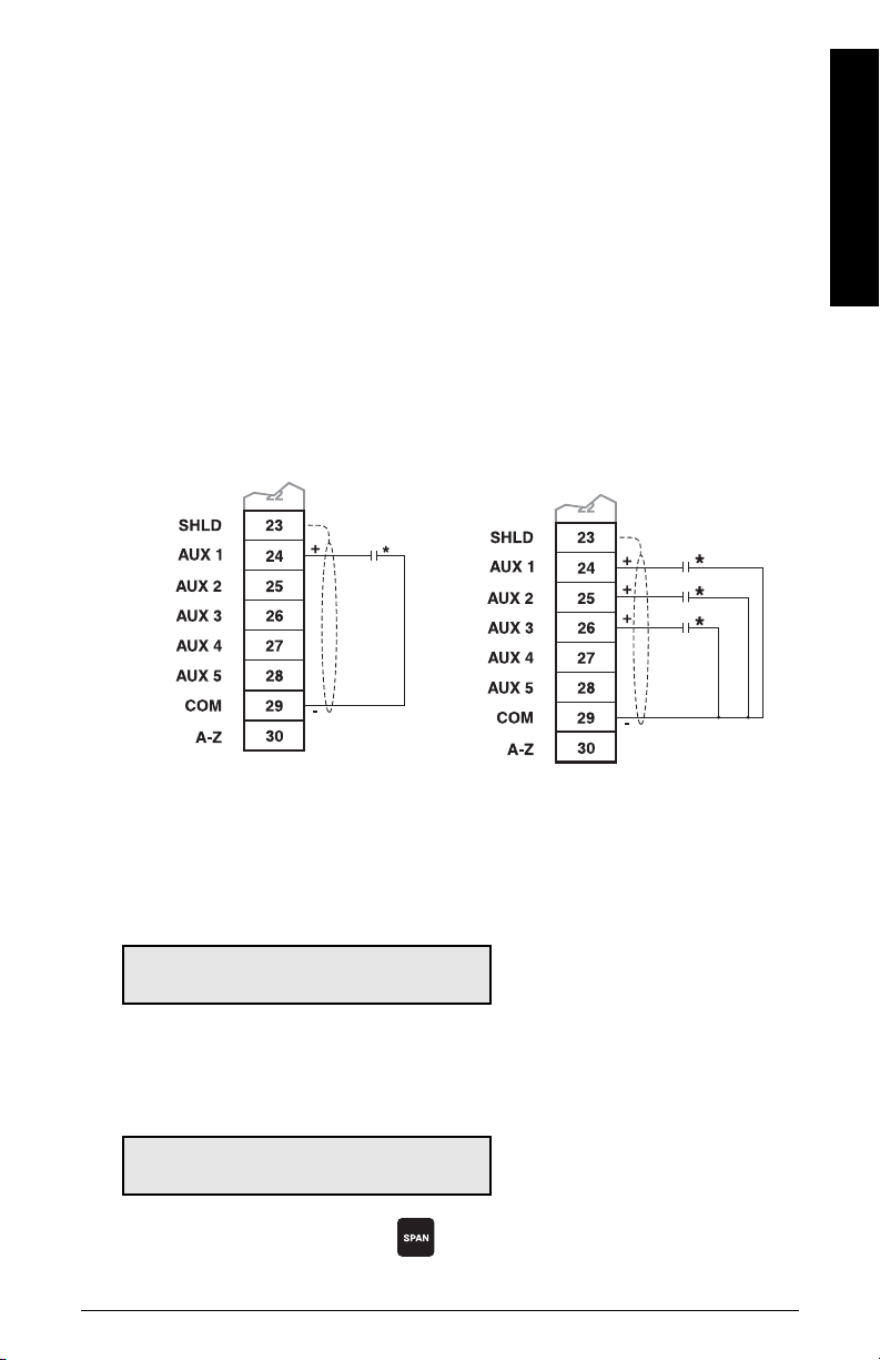
Each time one of the eight conditions is in effect, the corresponding multispan is selected
prior to putting the BW500 into the RUN mode. The selection is made by either changing
the multispan operation number, accessed via P365, or by external contacts connected to
the Auxiliary input, and programmed via P270.
To enable multispan operation, the following must be addressed.
• connections
• programming
• calibration
•operation
Connections
If the span selection is to be done by remote contact, the following connections would
apply. Otherwise, no additional connections to the BW500 are required.
Multispan Selection of Spans 1 and 2 Multispan Selection of Spans 1 to 8
Recalibration
*Remote contact can be from relay, open collector switch, or BCD switch.
Programming
Access P365 and enter EDIT mode
P365 Multispan E
Select [1-8] 0
Span 1 will have already been set as part of the Start Up and initial calibration. Therefore,
select 2.
Access P017 and enter EDIT mode
P017 Test Load: Weight MS2 E
Enter test load 0
Enter the test load value, and press
7ML19985DK05Milltronics BW500 and BW500/L - OPERATING INSTRUCTIONS Page 51
to do a span calibration.
Page 58
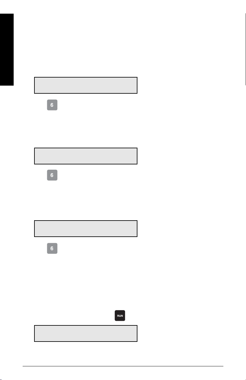
To do a span calibration for another condition, (i.e. span 3 or 4 etc.), access P365 and
repeat these steps for each condition. As with any initial span, follow the span calibration
for each multispan with a material test and factoring.
To use remote span selection, auxilliary Inputs, 1 and/or 2 or 3, are programmed to read
the contact state as the span selection. Remote selection overrides the keypad (or
Dolphin Plus) selection. The auxilliary inputs override the keypad selection.
Recalibration
Access P270 and enter EDIT mode
P270-01 Auxiliary Input Function E
Select Function [0-13] 0
Enter . This programs Auxiliary Input 1 (terminal 24) to read the contact state for
span selections: 1 or 2.
If spans 3 and/or 4 are to be used:
Access P270 and enter EDIT mode (when using spans 3 and/or 4)
P270-02 Auxiliary Input Function E
Select Function [0-13] 0
Enter . This programs Auxiliary Input 2 (terminal 25), in conjunction with Auxiliary
input 1 to read the contact state for span selections 3 and 4.
If spans 5, 6, 7, and/or 8 are to be used:
Access P270 and enter EDIT mode (when using spans 5 to 8)
P270-03 Auxiliary Input Function E
Select Function [0-13] 0
Enter . This programs Auxiliary Input 3 (terminal 26), in conjunction with Auxiliary
input 1 and Auxiliary input 2 to read the contact state for span selections 5, 6, 7, and 8.
Remote selection of a span is not enabled until a span calibration has been done. Initial
span selection must be done via the Multispan parameter, P365.
Initial multispan calibration or span selection is made via the Multispan parameter (P365).
Operation
When span calibration is done, press to revert to the RUN mode.
Rate kg/h 0.00 kg/h MS 2
Total 1: 0.00 kg
Page 52 Milltronics BW500 and BW500/L - OPERATING INSTRUCTIONS 7ML19985DK05
multispan 2
e.g. if there is no material on the belt and
the conveyor is running. The current rate
is 0 and no material has been totalized.
Page 59
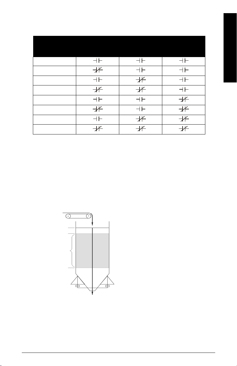
When the material to be run on the belt changes, the multispan is changed to the
feeder
Max. (e.g. 90%)
reference weight:
(the amount of
material held
between High
and Low levels)
10 t
High (e.g. 70%)
Low (e.g. 30%)
corresponding span. This is completed either by changing the span value entered in P365,
or by closing the appropriate contacts connected to the programmed Auxiliary inputs.
Multispan
Selection
Aux 3
Span
1
2
3
4
5
6
7
8
Auxiliary Input
Aux 1
Multispan
Selection Aux 2
It may be required to reset or note the totalizer value, as the process materials being
conveyed change. Refer to
Operation
on page 63.
Linearization applies concurrently to spans.
Recalibration
Online Calibration
The Online Calibration feature may be used to routinely check, and if necessary adjust,
the Span calibration in RUN mode, without interrupting the material flow or process.
1)
Not available with BW500/L.
1)
Install a weigh bin, (bin or silo equipped to
provide a 4 to 20 mA output proportional
to weight), preceding the material infeed.
Connect the weigh bin to one of the mA
inputs on the optional mA I/O board of the
BW500: either mA input 1, terminals 5 and
6; or mA input 2, terminals 7 and 8.
Install a material feed control device,
preceding the weigh bin.
7ML19985DK05Milltronics BW500 and BW500/L - OPERATING INSTRUCTIONS Page 53
Page 60
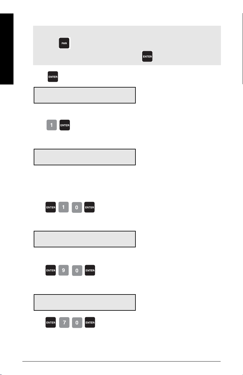
Recalibration
Note:
• Press twice, to enter a parameter number directly.
• Whenever you wish to change a value, press to enable the EDIT mode.
Press
P355 Online Calibration Feature E
EDIT mode: value can be changed
Select: 0-Off, 1-On 0
Select the Online Calibration feature:
Press
Access
P355 Online Calibration Features V
Select: 0-Off, 1-On 1
Enter the weigh bin reference weight, (the amount of material the bin holds between the
high and low levels), in units selected in P005.
Press
Value is accepted
Access
P356 Online Calibration V
Enter Reference Weight 10.000
Enter the max., high, and low limit setpoints as a percentage in P357.
e.g. reference bin weight
Press
Access
P357-01 Online Calibration Limits V
MAX Limit: 90.0
Press
Page 54 Milltronics BW500 and BW500/L - OPERATING INSTRUCTIONS 7ML19985DK05
limit as a percentage
Page 61
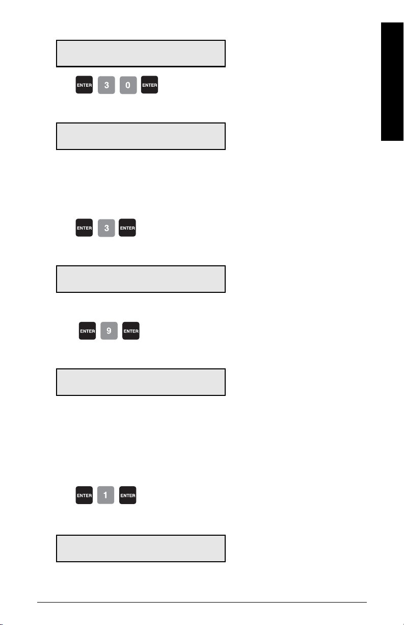
Access
P357-02 Online Calibration Limits V
HIGH Limit: 70.0
Press
Access
P357-03 Online Calibration Limits V
LOW Limit: 30.0
Calibrate the mA inputs on the BW500 to the 4 and 20 mA levels of the weigh bin. 4 mA is
calibrated with the weigh bin empty, using P261-01 or –02. 20 mA is calibrated with the
weigh bin full, using P262-01 and P262-02.
Assign one of the mA inputs for the Online Calibration function.
Press
Access
P255-01 mA Input Function V
Select 0, 1-PID SP, 2-PID FV, 3-OCAL 3
Assign one of the 5 relays, P100-01 to P100-05, to the Online Calibration function.
Press
e.g. mA input 1 set to 3
Recalibration
Access
P100-01 Relay Function V
Select Function [0-9] (see manual) 9
Program the assigned relay using P118, relay logic, so that when you connect the
assigned relay to the weigh bin material feed control device, the weigh bin material feed
stops when the Online relay is energized.
e.g. relay 1 set to 9
Activate Online Calibration
Press
Access
P358 Online Calibration Features V
0-OFF, 1-ACTIVE
7ML19985DK05Milltronics BW500 and BW500/L - OPERATING INSTRUCTIONS Page 55
Page 62

Recalibration
Note: For remote access, Online Calibration can also be activated using one of the
Auxiliary inputs (refer to
When the Online Calibration is activated, normal operation continues until the weigh bin
fills to the maximum level, (90% in the example shown). During the filling stage, the
current level is displayed as a percentage.
Online Calibration - LOW > 19%
Wait for LEVEL > MAX RLY
When the maximum limit is reached, the relay assigned to the Online Calibration function
energizes to stop the weigh bin material feed.
Online Calibration - 94% > MAX
Wait for LEVEL < HIGH RLY 1
Material continues to be discharged from the weigh bin, and when the level drops to the
High limit (70% in the example) the Online totalizer is automatically activated.
P270
on page 122).
current level displayed as percentage
Online Calibration - TOTAL 3.71 tonnes
Calibration in progress RLY 1
When the Low limit (30%) is reached, the totalizer is deactivated and the assigned relay is
de-energized, which reopens the material feed to the weigh bin.
running total
Page 56 Milltronics BW500 and BW500/L - OPERATING INSTRUCTIONS 7ML19985DK05
Page 63
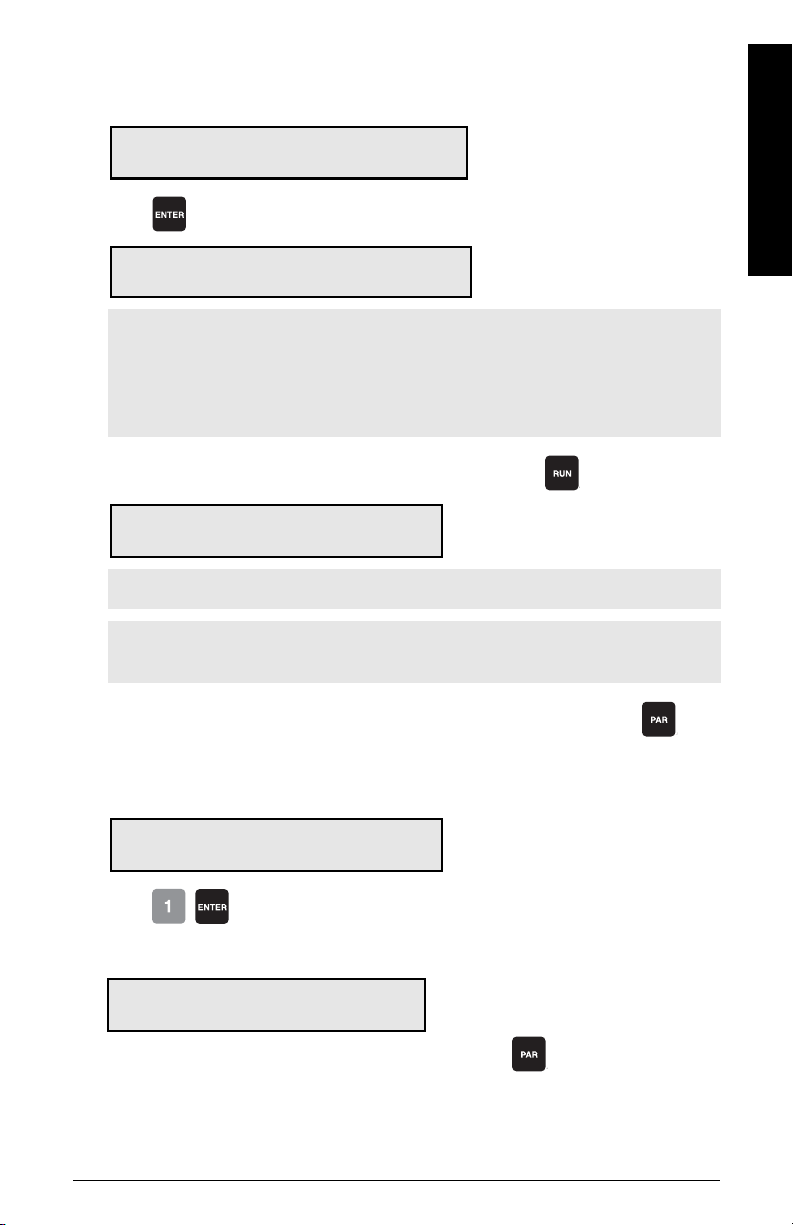
The BW500 Online material total, the amount of material totalized between the High and
Low limits, is compared to the value entered in P356. The deviation percentage between
these values and the new Span count value is displayed.
Recalibration
Online Calibration - Deviation 2.51%
Press ENTER to accept New span 22280
Press
Online Calibration Complete
Press ENTER to accept New span 22280
to accept the results.
deviation percent
new Span count value
Note:
• Deviation must be no greater than 12% of the initial span or it will not be
accepted.
• For remote access, Online Calibration can be accepted using one of the Auxiliary
P270
inputs: refer to
on page 122.
If you want to reject the results and return to RUN mode, press .
Rate 0.00 t/h
Total 1: 10.15 t
Note: t/h equals metric tonnes per hour
Note: For remote access, to return to RUN mode, program one of the Auxiliary inputs:
refer to
P270
on page 122
If you want to reject the results and perform another online calibration, press
to
return to P358.
Access
P358 Online Calibration Features V
0-OFF, 1-ACTIVE 1
Press
If the deviation is greater than 12%:
Calibration is out of range
Deviation Error:
1. Rerun online calibration to verify the deviation: press
2. Verify the mechanics of the belt scale: carry out material tests to ensure the
readings are correct. (See page 42)
3. If the mechanics are functioning correctly, perform an initial span using P388. (See
page 49.)
7ML19985DK05Milltronics BW500 and BW500/L - OPERATING INSTRUCTIONS Page 57
to return to P358.
Page 64
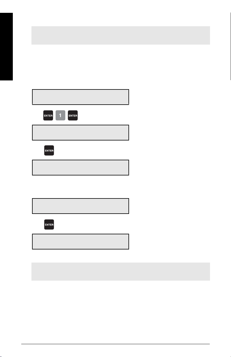
Factoring
Recalibration
Note: For optimum accuracy in the factoring results, a routine zero calibration is
recommended.
To calculate the value of a new or unknown test weight to the current span, the factoring
procedure is used.
With the belt empty, the test weight in place, and the conveyor running:
Access P359 in VIEW mode
P359 Factoring V
Select 1-Weight, 2-Chain
Press
Factoring Weight
Place weight and press ENTER.
Press
Factoring Weight
Factoring in progress ##.## kg/m
Factoring Weight
Press ENTER to accept value 45.25
Press
P017 Test Load Weight: V
Enter Test Load 45.25
Factoring is complete. Remove test weight and return to RUN mode if desired.
e.g. factor the test weight
the load reported while factoring is in
progress
e.g. the new factor, if accepted
e.g. the current test load value
Note: If multispan function is used, the test load value is stored for the current
multispan only.
Page 58 Milltronics BW500 and BW500/L - OPERATING INSTRUCTIONS 7ML19985DK05
Page 65

Linearization
Conveyor applications where the ideal belt scale location has been compromised, or
where there is a high degree of variation in belt tension, typically cause the belt scale to
report load non-linearly. The BW500 and BW500/L provides a linearizing function (P390 P392) to correct for the deficiency in the weighing system and to provide an accurate
report of the actual process.
To verify that the cause of the non-linearity is not mechanical:
• Run the conveyor belt empty and stop it.
• Lift the belt off of the scale and suspend various test weights to the scale.
If the load reported by the BW500 and BW500/L is non-linear, a mechanical problem
is indicated. Refer to the belt scale manual to resolve the non-linearity by improved
installation or repair.
If it is determined that the non-linearity is due to the weighing application,
and not the actual belt scale, apply linearization by performing the
following:
• zero calibration
• span calibration at 90 to 100% of design rate
• material tests at 90 to 100% of design rate
• manual span adjust if required
• material tests at 1 to 5 intermediary flow rates where compensation is required.
Note: Compensation points must be at least 10% of the design load apart.
• calculate the percentage compensation for each flow rate tested.
% compensation = actual weight - totalized weight x 100
totalized weight
Recalibration
where:
actual weight = material test
totalized weight = BW500 and BW500/L total
Note:
• After the compensation has been programmed into the BW500 and BW500/L, a
material test should be run to verify the effect of linearization.
• If additional compensation is required, it must be based on new material tests
performed with the linearization turned off (P390 = 0).
7ML19985DK05Milltronics BW500 and BW500/L - OPERATING INSTRUCTIONS Page 59
Page 66
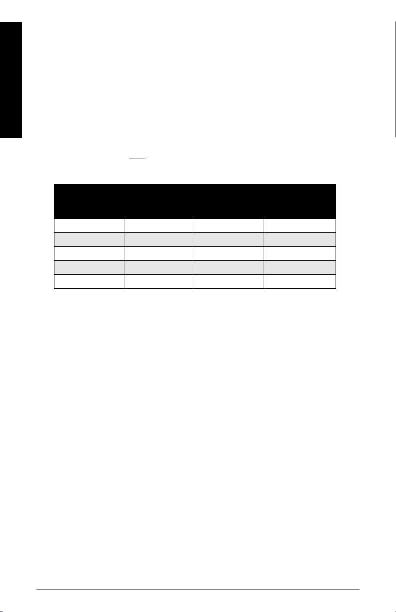
Recalibration
Example:
A non-linearity with respect to the ideal response exists in a belt scale application with
design rate of 200 t/h. It is decided to do material tests at 15, 30, 45, 60 and 75% of the
design load. After performing a zero and a span calibration at 100% of the design load,
followed by material tests and manual span adjust, five material tests were performed at
30, 60, 90, 120 and 150 t/h, as indicated by the BW500. The following data was tabulated.
(This example is exaggerated for emphasis).
The material tests should be run at same belt speed, representative of normal operation;
in this case 1.2 m/s. For each rate, record the corresponding load value by scrolling to the
BW500 load display during running conditions or by calculation.
load = rate
speed
BW500 load material test BW500 total
kg/m tonnes tonnes %
6.94 2.5 2.8 -10.7
13.89 5.0 4.5 11.1
20.83 7.5 7.9 -5.1
27.78 10.0 9.2 8.7
34.72 12.5 13.3 -6.0
a)
calculation example: % compensation = [(2.5 – 2.8) x 100]/2.8
compensation
a)
Page 60 Milltronics BW500 and BW500/L - OPERATING INSTRUCTIONS 7ML19985DK05
Page 67
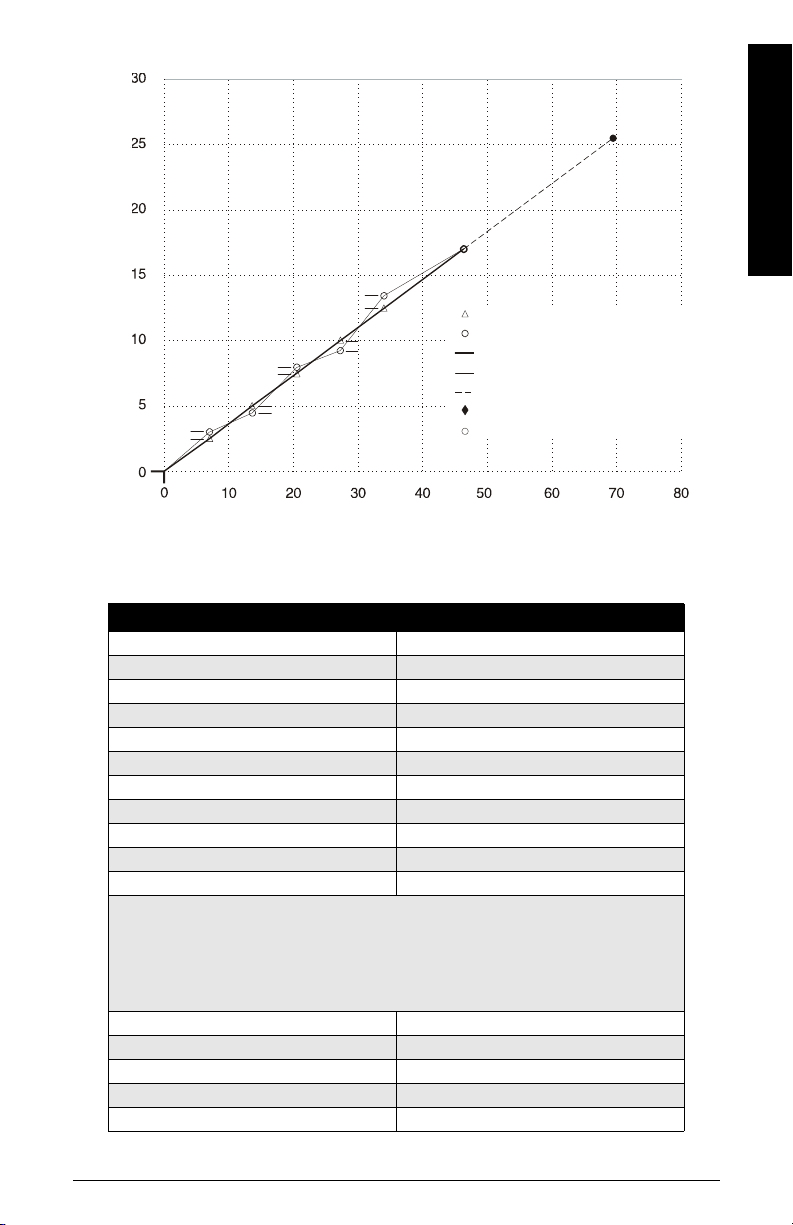
= - 10.7
Weight = Tonnes
actual weight per material test
totalized weight by BW500
belt scale response
linearized BW500 response
internal response 100% - 150% of span
% compensation
span (100%)
-5.1
-6.0
-10.7
8.7
11.1
Load - kg/m
Recalibration
Program the BW500 as follows:
Parameter Function
P390 = 1 linearization – on
P391-01 = 6.94 point 1, load
P391-02 = 13.89 point 2, load
P391-03 = 20.83 point 3, load
P391-04 = 27.78 point 4, load
P391-05 = 34.72 point 5, load
P392-01 = - 10.7 point 1, compensation
P392-02 = 11.1 point 2, compensation
P392-03 = - 5.1 point 3, compensation
P392-04 = 8.7 point 4, compensation
P392-05 = -6.0 point 5, compensation
Note: Often only one point of compensation is required, usually at a low load
value. In the prior example, if compensation was only required at 6.94 kg/m, the
programming could be as follows. Compensation is optimized by establishing the
next load value that agrees with the material test, hence where compensation is
zero and entering it as the next compensation point.
P390 = 1 linearization on
P391-01 = 6.94 point 1, load
P391-02 = 20.00 point 2, load
P392-01 = -10.7 point 1, compensation
P392-02 = 0 point 2, compensation
7ML19985DK05Milltronics BW500 and BW500/L - OPERATING INSTRUCTIONS Page 61
Page 68
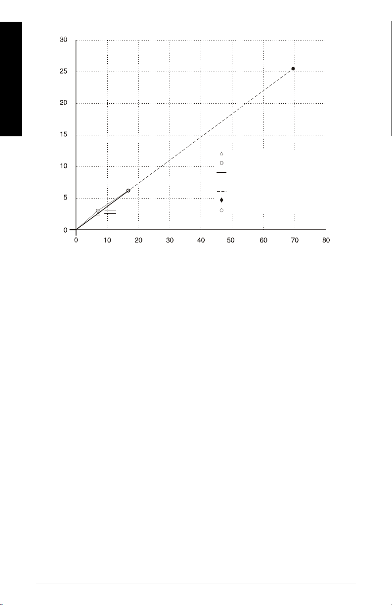
Recalibration
Weight = Tonnes
actual weight per material test
totalized weight by BW500
belt scale response
linearized BW500 response
internal response 100% - 150% of span
% compensation
span (100%)
-10.7
Load - kg/m
For Parameter reference, go to Parameters on page 111.
Page 62 Milltronics BW500 and BW500/L - OPERATING INSTRUCTIONS 7ML19985DK05
Page 69

Operation
Load Sensing
For the BW500 and BW500/L to calculate rate and totalize material flow along the belt
conveyor, a load signal representative of weight of material on the belt is required. The
load signal is provided by the belt scale. The BW500 and BW500/L is compatible with belt
scales fitted with 1, 2, 4, or 6
sensors, an optional LVDT conditioning card is required.
Specifications
Refer to
and connection.
Speed Sensing
For the BW500 and BW500/L to calculate rate and totalize material flow along the belt
conveyor, a speed signal representative of belt speed is required. For optimum accuracy
of the weighing system, and both constant and variable speed applications, a speed
sensor is required. The design speed (P014) and speed constant (P015) need to be
programmed.
In constant speed applications (no speed sensor), the BW500 can be programmed to
provide an internal speed signal. This is achieved by entering the design speed (P014) and
providing a contact closure across speed input terminals (17/18). The speed constant
(P015) defaults to ‘jumpered’. This contact should change to open when the conveyor is
idle to prevent errant totalization.
In applications with two speed sensors, the BW500 can be programmed to provide
differential speed. % slip can be calculated, using the difference between the two speed
signals with reference to the first speed.
Refer to
Specifications
requirements and connection.
1)
strain gauge type load cells. To function with LVDT type
on page 5, and
on page 5 and
Installation
2)
Installation
on page 9 for belt scale requirements
on page 9 for speed sensor
Operation
Differential Speed Detection
Dual point speed sensing is used for monitoring speed at two points in the system where
a difference in speed can be detrimental to the equipment or its operation. The two speed
sensors are typically applied on belt conveyors to give an alarm if excessive slip between
the head pulley and tail pulley is detected. The secondary speed sensor is especially
useful on variable speed conveyors, and may also be used to detect a malfunction in the
primary speed sensor.
The BW500 provides a 12 V DC, 150 mA maximum, regulated power supply for both
speed sensors. The primary speed sensor is used for all "Run" display integration, and is
the reference value for differential speed detection. The primary speed sensor is
generally reserved for the driven device (tail pulley). The second speed sensor is
1)
Not available with BW500/L
2)
Differential speed detection is not available on the BW500/L
7ML19985DK05Milltronics BW500 and BW500/L - OPERATING INSTRUCTIONS Page 63
2)
Page 70

Operation
generally reserved for the driving device (head pulley), and is used for comparison to the
primary speed sensor, for differential speed detection only.
The second speed signal is compared to the primary speed signal, and will initiate an
alarm condition if the second speed signal is outside the programmed high and low alarm
setpoints.
Connect the second speed sensor as shown in the Installation section (refer to
Speed Sensor
following steps:
1. Program one of the Auxiliary Inputs as a Speed Sensor input P270-01 to 05 = 16
2. Program second speed sensors speed constant P015-02 = pulses per meter or foot
3. Program one of the alarms for Differential Speed Detection alarm P100-01 to 05 = 10
4. Program the High Alarm setpoint P101-01 to 05 = 110% (default).
5. Program the Low Alarm setpoint P102-01 to 05 = 90% (default).
on page 21), and program the second speed sensor as described in the
(Speed Sensor).
Start Up
(Refer to
(Speed Differential).
on page 28, for speed sensor programming).
Auxiliary
Moisture Compensation
Moisture Compensation is used to compensate for the moisture component of the
material being weighed. It factors out the moisture component of load, rate and total for
all multispans selected. The factored value is meant to report the dry mean values of the
material being conveyed.
The BW500 receives the static load cell signal, and adjusts the value of the load being
displayed and integrated by the moisture percentage. The mA I/O card is required to
accept the mA signal from the Moisture Meter. This mA signal can represent 0 to 100%
moisture. The moisture percentage is displayed in P398-01. Using P398-02, the moisture
percentage can be represented as a percentage of mass to be deducted from the total
1)
.
mass
1)
1)
The BW500/L allows for a fixed moisture content to be entered. See “P398-01
Moisture Content” on page 129.
Page 64 Milltronics BW500 and BW500/L - OPERATING INSTRUCTIONS 7ML19985DK05
Page 71

Example:
Setting P398-02 = 30% will allow the 4 - 20 mA input to correspond to 0 - 30% moisture.
The Zero and Span calibration is not affected by the presence of a moisture meter. It is
understood that the calibrations are performed using dry static weights.
The Moisture Meter must be connected to the appropriate mA input and programmed as
described in the following steps:
1. Enable mA input function for moisture compensation P255-01 or 02 = 4 (moisture
compensation).
2. Set appropriate mA input range P250-01 or 02 = 2 (default is 4 - 20 mA).
3. Set mA input moisture ratio P398-02 = 100% (default).
4. Observe moisture percentage using P398-01.
Incline Compensation
Incline compensation is used to compensate for the varying vertical force component
applied to the belt scale due to varying inclination of the conveyor. The BW500 and
BW500/L receives the static load cell signal, and adjusts the load displayed and
integrated, by a factor of COSINE of the angle of incline.
The Inclinometer should be mounted to the conveyor stringer, parallel to the center of the
belt scale. The mA I/O card is required to accept the mA signal from the Inclinometer. This
mA signal must represent -30 to 30°. The incline angle is displayed in P399.
The dynamic load cell signal will vary with the incline of the conveyor. The BW500 and
BW500/L load display and integration values will remain constant for the given load on
the belt scale through the specified range of inclination.
The Zero and Span calibrations of the BW500 and BW500/L will be adjusted based on the
angle of incline of the conveyor. The Zero and Span calibration can be performed at any
angle. However, if incline compensation will be used, it must be enabled for all Zero and
Span calibrations
1)
.
1)
Operation
The Inclinometer must be connected to the appropriate mA input and programmed as
described in the following steps:
1. Enable mA input function for incline compensation P255-01 or 02 = 5 (Incline
compensation).
2. Set appropriate mA input range P250-01 or 02 = 2 (default is 4 - 20 mA).
3. Observe incline angle using P399.
Modes of Operation
RUN is the normal or reference mode of operation. It continuously processes the load
and speed signals from the belt scale to produce internal load, speed and rate signals,
which are in turn used as the basis for totalization, mA output, relay control, and
communication data. The RUN display is programmed (P081) to scroll through rate,
1)
The BW500/L allows for a fixed inclined angle to be entered. See “P399 Incline
Sensing” on page 130.
7ML19985DK05Milltronics BW500 and BW500/L - OPERATING INSTRUCTIONS Page 65
Page 72

Operation
Damping
totalization (P647), load and speed; either manually by pressing the enter key, or
automatically.
Rate Rate Load
Total 1 To t al 2 Speed
If the BW500 is programmed for batch control, the batch display is added to the display
scroll. Refer to
From the RUN mode, access to the PROGRAM mode, and zero and span calibration is
made.
The PROGRAM mode allows viewing and, with security permission (P000), editing
parameter values. During PROGRAM, RUN mode functions are still active, i.e.: rate, relay,
mA output and totalization.
If the PROGRAM mode is left idle for a period of ten minutes, it automatically reverts to
RUN mode.
Zero and span calibrations effectively halt the RUN mode while they are in progress.
During this time, totalization ceases, and all mA outputs, except for PID, fall to zero.
Damping (P080) provides control over the speed at which the displayed readings and
output functions respond to changes in their respective input function: load, speed and
the internal rate signals. Changes in the displayed rate of material flow, material loading
and belt speed are controlled by the damping. Relay alarm functions based on input
functions of rate, load and speed, respond to the damped value.
Damping consists of a first order filter applied to the signal (reading or output value).
If mA damping (P220) is enabled (value other than 0), then the damping (P080), as it
pertains to the mA function, is overridden, and responds independently at the specified
mA output damping rate (P220).
Batch Control
on page 134 for more information.
Note: Damping (P080 or P220) is not applicable to the mA output when programmed
for PID function (P201 = 4).
mA I/O (0/4-20 mA)
Output
The standard BW500 and BW500/L provides one isolated mA output. The output can be
assigned (P201) to represent rate, load or speed. The output range can be set to 0 - 20 mA
or 4 - 20 mA (P200). The 0 or 4 mA value corresponds to empty or zero condition, whereas
the 20 mA value corresponds to the associated design value: rate (P011), load (P952), or
speed (P014). The mA output can be limited for over range levels of 0 mA minimum and
22 mA maximum (P212 and P213 respectively). The output 4 and 20 mA levels can also be
trimmed (P214 and P215 respectively) to agree with a milliammeter or other external mA
device.
Page 66 Milltronics BW500 and BW500/L - OPERATING INSTRUCTIONS 7ML19985DK05
Page 73

The mA output value can be tested to output a prescribed value using parameter P911.
P911
Refer to
The optional mA I/O board provides two additional mA outputs
on page 145.
1)
, programmable as
outputs 2 and 3, using the same parameters as the standard output (1). If programmed for
PID control, output 2 is assigned to PID control loop 1 and output 3 is assigned to PID
control loop 2.
1)
Input
The optional mA I/O board provides two mA inputs, programmable as inputs 1 and 2. If
programmed for PID control, generally, input 1 is assigned to PID control loop 1 and input
2 is assigned to PID control loop 2.
The input range can be set to 0-20 mA or 4-20 mA (P250), and assigned a function (P255),
e.g. PID setpoint. The 4 and 20 mA levels can be trimmed (P261 and P262) to agree with an
external device. The external device could be a moisture sensor, or an inclinometer.
Relay Output
The BW500 offers five single pole single throw (SPST) relays that can be assigned (P100)
to one of the following alarm functions, the BW500/L offers two relays of the same type:
• rate: relay alarms on high and/or low material flow rate.
• load: relay alarms on high and/or low belt load.
• speed: relay alarms on high and/or low belt speed.
• differential speed
alarm setpoints.
•diagnostic
1) 2)
•PID
: PID control setpoint deviation
• batch pre-warn
• batch setpoint
1)
:relay alarms if second speed signal outside high and/or low
1) 2)
: relay alarms on any error condition as it is reported. See
“Troubleshooting” on page 148.
1)
1)
Operation
For rate, load, and speed alarm functions, the high and low alarm setpoints (P101 and
P102 respectively) are required and must be entered in the appropriate units. The high
alarm setpoint acts as the setpoint deviation alarm for relays programmed for PID
setpoint deviation.
The on/off actuation at both high and low setpoints is buffered by the damping (P080) and
the programmable dead band (P117), to prevent relay chatter due to fluctuations. The
relay is normally energized; holding the normally open (n.o.) contact closed (can be
programmed for reverse operation, P118). Upon an alarm condition, the relay is deenergized and the relay contact is opened. Once in alarm, the relay remains in alarm
state until the alarm condition is removed.
1)
Not available with BW500/L
2)
Is offered only if the PID system (P400) is enabled.
7ML19985DK05Milltronics BW500 and BW500/L - OPERATING INSTRUCTIONS Page 67
Page 74
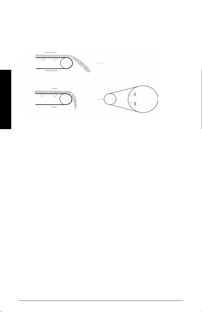
Example:
2 m/s
0.4 m/s
high
100%
low
20%
2 %
actual low
alarm
’off’ = 22%
’on’ = 20%
P014 = 2m/s, design speed
P100 = 3, belt speed
P101 = 100% (2 m/s)
P102 = 20% (0.4 m/s)
P117 = 2% (0.04 m/s)
Operation
alarm ‘on’ is with relay de-energized
Totalization
The totalization function is based on the internal rate (mass per unit time) signal
proportional to belt speed and load on the associated belt scale. It is not affected by the
damping function (P080). The rate signal is sampled several times a second to accurately
count the mass of material conveyed. The count is held in the master totalizer used to
increment the internal totalizers and to produce a pulse signal for the remote totalizers.
The BW500 provides several separate totalizer functions:
Internal totalizers
• local display (totalizers 1 and 2)
• verification totalizer (totalizer 3)
• material test totalizer (totalizer 4)
• batch total (totalizer 5)
External totalizers
• totalizer outputs (remote totalizers 1 and 2)
To avoid totalizing material at flow rates below the low flow rate limit, the totalizer drop
out limit (P619) is set to a percentage of the design load. Below this limit, totalization
stops. When material flow returns to a rate above the drop out limit, totalization resumes.
Totalizer resolution or count value is set by the respective internal (P631) and external
(P638) totalizer
1)
If the resolution selected causes the totalizer to lag behind the count rate, the
1)
resolution parameters.
next possible resolution is automatically entered.
Page 68 Milltronics BW500 and BW500/L - OPERATING INSTRUCTIONS 7ML19985DK05
Page 75

Example:
Internal totalizer 1
External totalizer 1
Given: P005 = 1 (t/h)
P631 = 4
Then: totalizer count increments by 10 for each 10 metric tonnes registered
Given: P005 = 1 (t/h)
P638 = 5
Then: contact closure occurs once for every 10 metric tonnes registered
For remote totalization, the contact closure duration (P643) is automatically calculated
upon entry of the design rate (P011) and remote totalizer (P638) parameters, so that the
duration of contact closure allows the relay response to track the total up to 150% of the
design rate. The value can be changed to suit specific contact closure requirements, such
as in the case of programmable logic controllers. If the duration selected is inappropriate,
the next possible duration is automatically entered.
External Totalizer Calculation Example:
Design Rate = 50 t/h (P011)
External Totalizer Resolution Selected = 0.001 (P638 = 1)
External Totalizer Contact Closure Time selected = 30 msec (P643 = 30)
External Totalizer Cycle Time = 60 msec (External Totalizer Contact Closure Time X 2)
1. Calculate the maximum number of pulses per second for the Contact Closure Time
selected (P643).
Maximum Number of pulses per second
= 1 / External Totalizer Cycle Time
= 1 / 0.060
= 16.6 (which is rounded to a whole number of 16 in the BW500)
2. Calculate the pulses per second required for the External Totalizer Resolution
selected (P638).
Pulses Per Second = Design Rate X 150%
External Totalizer Resolution X 3600
= 50 t/h X 150%
0.001 X 3600
Operation
= 20.83
Because the required 20.83 pulses per second is greater than the maximum 16 pulses per
second, the External Totalizer Resolution of 0.001 will not allow the External Totalizer to
track up to 150% of the design rate. The External Totalizer Resolution will have to be
increased to 0.01 or the External Totalizer Contact Closure Time will have to be
decreased.
7ML19985DK05Milltronics BW500 and BW500/L - OPERATING INSTRUCTIONS Page 69
Page 76

Operation
The totalizers are reset through the master reset (P999), the totalizer reset (P648), or
through the keypad.
• master reset: the reset of all totalizer functions is included in the master reset.
• totalizer reset: totalizer reset can be used to reset internal totalizers 1 and 2, or
totalizer 2 independently. Resetting the internal totalizers 1 and 2
resets the internal registers for external totalizers 1 and 2.
• keypad: pressing while in the RUN mode resets internal totalizer 1
Placing the internal totalizers on to the display scroll of the RUN mode is controlled by the
totalizer display parameter (P647); displaying either one or both totalizers.
Page 70 Milltronics BW500 and BW500/L - OPERATING INSTRUCTIONS 7ML19985DK05
Page 77

PID Control
1)
The PID control algorithm in the BW500 is designed specifically to work for feed rate
control applications. It is based on motor control type algorithms and includes several
anti-wind up provisions.
One way to prevent wind up is to monitor the input speed frequency from the
weighfeeder. If the input frequency drops below 5 Hz, the PID control output freezes at its
current value. Otherwise, the output winds up to 100% if the feeder is shut off while there
is still a set point greater than zero. When the feeder is turned back on, there would be a
surge of product flow until the system regains stability. With anti-wind up, the feeder can
be stopped and started with minimal disruption to the controlled flow rate.
To operate the BW500 as a controller, address the following:
• hardware
• connections
• setup and tuning
• programming
Hardware
For the BW500 to operate as a controller, install the optional mA I/O board. Refer to
Installation
on page 9.
Connections
Connections to process instruments, in addition to standard operating connections, must
be made.
Refer to:
Installation
•
Relay Output
•
mA I/O board
•
•
Auxiliary Inputs
Connect the BW500 as either a:
1. setpoint controller – load control
2. setpoint controller – rate control
3. setpoint controller – rate and load control
4. setpoint controller – external process variable with or without rate and load control
1)
Not available on the BW500/L.
on page 9, specifically:
on page 24, for relay connections
on page 12, for mA input and output connections
on page 22, for optional remote control
PID loop mA output
1 21 & 215 & 6
2 33 & 427 & 8
terminals
(mA I/O)
mA input
terminal
(mA I/O)
PID Control
7ML19985DK05Milltronics BW500 and BW500/L - OPERATING INSTRUCTIONS Page 71
Page 78
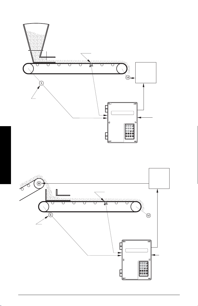
Setpoint Controller – Rate Control
shearing weighfeeder
belt scale
speed
sensor
speed
load
control output
(P201-02 = 4)
optoinal remote
setpoint - rate
(P255-01 = 1)
motor
speed
controller
PID 1 process value source - rate (P402-01 = 1)
belt scale
speed
sensor
speed
load
control output
(P201-02 = 4)
optoinal remote
setpoint - rate
(P255-01 = 1)
PID 1 process value source - load (P402-01 = 2)
motor
speed
controller
Setpoint Controller – Load Control
PID Control
Page 72 Milltronics BW500 and BW500/L - OPERATING INSTRUCTIONS 7ML19985DK05
Page 79
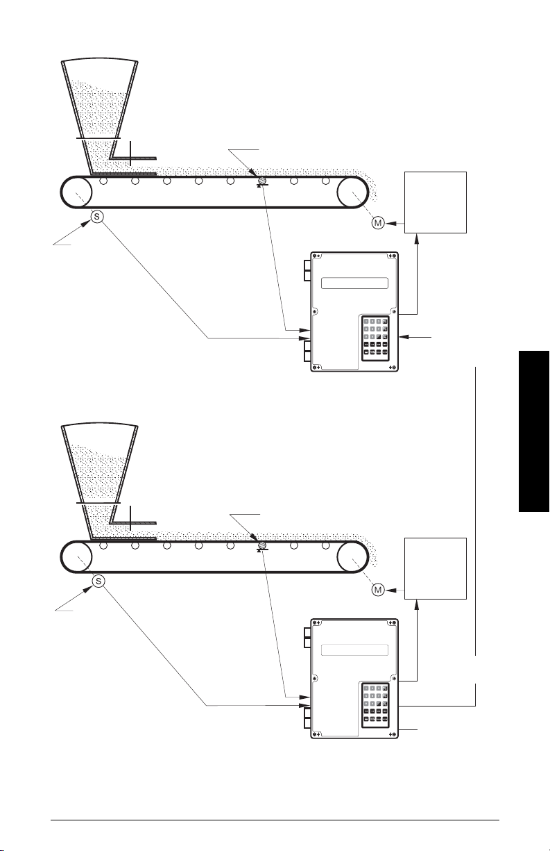
Setpoint Controller – Master/Slave Control
belt scale
speed
sensor
speed
load
PID 1 process value source - rate (P402-01 = 1)
belt scale
speed
sensor
speed
load
PID 1 process value source - load (P402-01 = 1)
motor
speed
controller
motor
speed
controller
control output rate
(P201-02 = 4)
remote ratio
setpoint rate
(P255-01 = 1
P418-01 to suit)
control
output
(P201-02 = 4)
rate*
(P201-01 = 1)
MASTER
remote setpoint rate
(P255 - 01 = 1)
SLAVE
*P201-03 = 1 also applicable
7ML19985DK05Milltronics BW500 and BW500/L - OPERATING INSTRUCTIONS Page 73
PID Control
Page 80
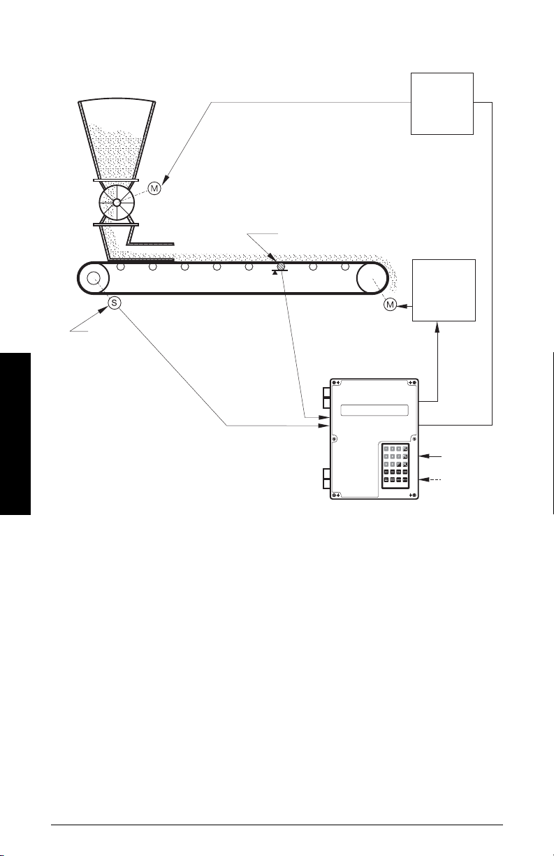
Setpoint Controller – Rate and Load Control
belt scale
speed
sensor
speed
load
motor
speed
controller
- load
motor
speed
controller
- rate
PID 1 process value source - load (P402-01 = 2)
PID 2 process value source - rate (P402-02 = 1)
PID 1 control
output,
(P201-02 = 4)
PID 2
control output,
(P201-03 = 4)
PID 1 remote
setpoint - load
(P255-01 = 1)
PID 2 remote
setpoint - rate
(P255-02 = 1)
PID Control
Setup and Tuning
Before proceeding, it would be beneficial to qualify and quantify the terms you will
encounter in the setup and tuning of the control system.
Proportional Control (Gain),
The P term on the BW500 adjusts the control output based on the difference between the
set point and the measured flow rate. A higher
P
P
term makes the BW500 more sensitive
and faster to react to changes or disturbances. If set too high, the BW500 becomes less
stable, and more susceptible to oscillations in the control output.
• allowable input range: 0.00 0 to 2.000
• typical operating range: 0.300 to 0.600
• default value: 0.400
Page 74 Milltronics BW500 and BW500/L - OPERATING INSTRUCTIONS 7ML19985DK05
Page 81

The control output cannot reach the setpoint using only the P term. Since the P term acts
on the difference between the setpoint and process variable, a small difference between
P
these two always exist and the difference is never zero. A small
process very close to set point, but it would take a very long time. At the very least, an I
P
term is required to eliminate the offset created by the
term.
term can get the
Integral Control (Automatic Reset), I
The I term on the BW500 is used to increase or reduce the amount of control output to
P
eliminate the offset caused by the
error over small increments of time. As the process reaches setpoint and the error
becomes small, the effect of the I term decreases. A higher I term makes the BW500
faster to react to changes, but can also make it less stable.
• allowable input range: 0.00 0 to 2.000
• typical operating range: 0.100 to 0.300
• default value: 0.200
P
and I terms together can make a suitable control algorithm and for many
The
applications, they work fine. However, if faster response to changes is desired, it is
P
necessary to use larger
unstable. A derivative term is needed to influence the control output as the process
variable approaches the set point.
and I terms. Unfortunately, larger terms can make the system
term. The I term acts on the
accumulation
of the
PID Control
7ML19985DK05Milltronics BW500 and BW500/L - OPERATING INSTRUCTIONS Page 75
Page 82
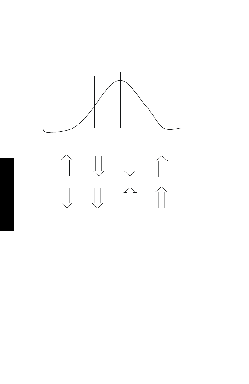
Derivative Control (Pre-Act or Rate),
Error
+
-
Setpoint
The D term on the BW500 influences the control output based on changes in the
magnitude and direction of the change in error. If there is a constant error, the
no effect. As the error gets larger, the D term combines with the P term to make the
BW500 control output respond faster. When the error is getting smaller, the D term acts to
reduce the amount of control output to help prevent overshooting the set point. In
P
general, a higher
term will require a larger D term.
D
D
term has
Decreasing
Error
Direction of
Proportional
Action
Direction of
Derivative
Action
PID Control
• allowable input range: 0.00 0 to 1.000
• typical operating range: 0.010 to 0.100
• default value: 0.050
The result of the derivative action is that it can make a system more responsive and more
stable at the same time.
Feed Forward Control,
On the BW500, the F term is used to adjust the control output based on a setpoint change.
The use of this term can make the system reach the new setpoint faster. If the term is not
used, the system responds using the
new setpoint and the process variable is the error and the control algorithm responds to
eliminate this new error.
F
term is used and a new setpoint is entered, a proportion of the difference
P, I
When the
between the new setpoint and the process variable is automatically added on to the
control output. This shifts the process variable closer to the new setpoint faster than
using the
• allowable input range: 0.00 0 to 1.000
• typical operating range: 0.250 to 0.550
• default value: 0.300
Increasing
Error
Decreasing
Error
Increasing
Error
F
P
, I and
D
terms only. The difference between the
and D terms alone. This is done on a one time basis.
Page 76 Milltronics BW500 and BW500/L - OPERATING INSTRUCTIONS 7ML19985DK05
Page 83

The PID control function of the BW500 can be configured to operate in several modes.
P term is too high SETPOINT
• controller output: direct acting
• feedback: rate, load, or external
• control: local or remote (ratio) setpoint
PID Setup and Tuning
Proper tuning of the control PID terms is essential to system operation and optimum
performance from the feeder. The recommended procedures for tuning the PID control
terms at initial start-up are described in this section.
Initial Start-Up
Although the default values of the P, I, D, and F terms will suit the majority of applications,
shearing weigh feeders in particular, some tuning will be necessary nonetheless.
There are several techniques and procedures for tuning conventional PID controllers,
some work better depending upon the application. We recommend using "closed-loop
cycling" for the BW500 integrator/controller for feed rate control. This technique focuses
on tuning the P term first while disabling the I and D terms. This is followed by adding and
tuning the I term, then the D term. To outline this procedure:
1. With the P term set to its default value of 0.400, disable the I, D, and F terms by
setting them to 0.000.
2. Enter a feed rate setpoint that is 30% of the designed maximum flow rate.
3. Having applied the test weights or chain provided, start the feeder and observe the
time it takes the feeder to reach setpoint, also observe the oscillation around
setpoint.
4. Adjust the P term accordingly for consistent oscillation and error. Progressively
decrease the P term value if there is too much oscillation and error. Likewise,
increase the value if the error is not consistent and oscillating around the setpoint.
Refer to figures 1, 2, and 3 below.
PID Control
Figure 1
7ML19985DK05Milltronics BW500 and BW500/L - OPERATING INSTRUCTIONS Page 77
Page 84
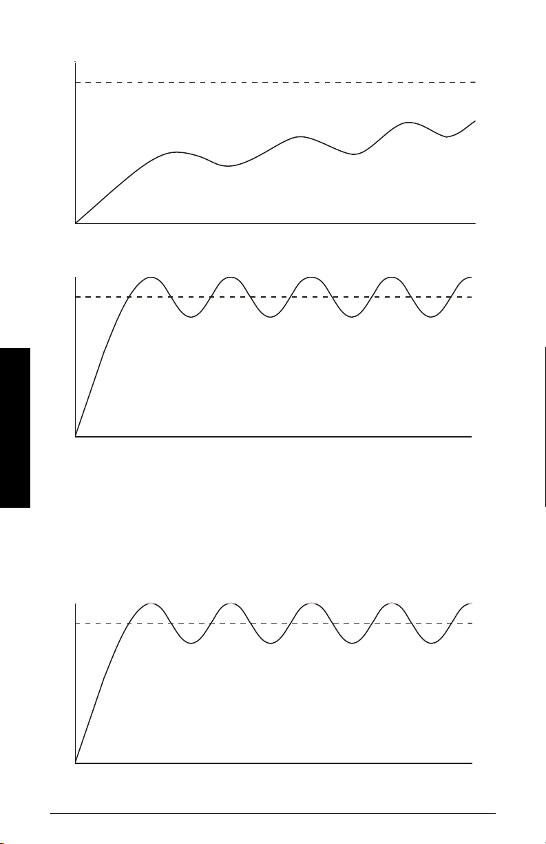
Figure 2
SETPOINT
P term is too low
SETPOINT
P term is correctly set
SETPOINT
I term is too high
Figure 3
PID Control
5. Once the P term value is set to give the control output of the BW500 consistent
oscillation and the error is at its minimum, turn the feeder off.
6. The I term value can now be set. Begin by entering the default value of 0.2.
7. Restart the feeder (test weights or chains still applied) and feed rate setpoint
entered.
8. Again observe the oscillation of the control output. Compare results to the figures 4,5
and 6 below.
Figure 4
Page 78 Milltronics BW500 and BW500/L - OPERATING INSTRUCTIONS 7ML19985DK05
Page 85
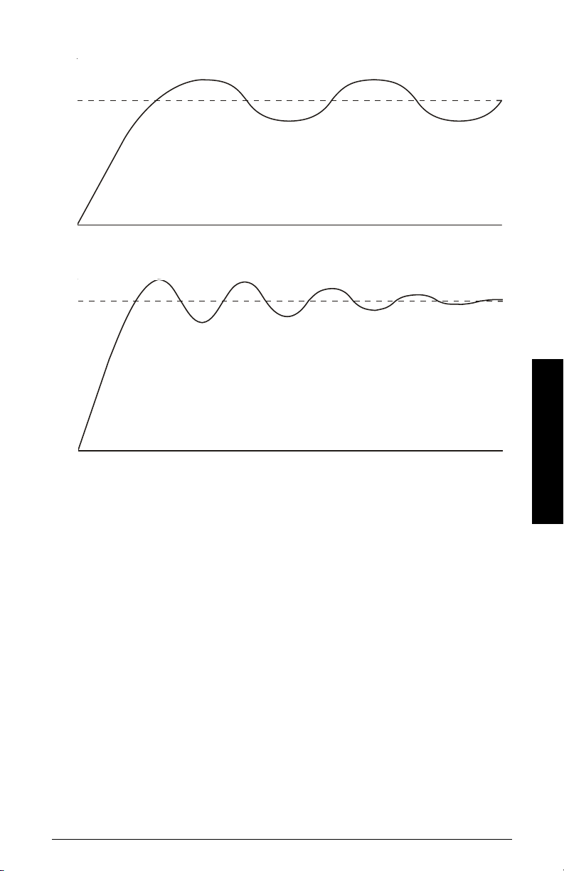
Figure 5
SETPOINT
I term is too low
SETPOINT
I term is correctly set
Figure 6
PID Control
9. The D term is not critical in typical shearing type weigh feeder applications. The
purpose of the D term is to anticipate where the process is heading by looking at the
D
time, rate, and direction of change of the process variable. The
term becomes very
useful in applications where the material control point is far away from the
measuring point. An example of this would be a weigh belt or conveyor with a belt
scale (constant speed) being fed from a pre-feeder some distance or more than a
few seconds process time from the scale.
D
A properly set
in figure 6. A
D
term, or set too low, shows no effect on the system.
the
term will make the initial oscillations around the setpoint smaller, as
D
term set too high induces high oscillations, as in figure 4. Omission of
10. The above closed loop cycling procedure allows ease in start up, but final
adjustments may be necessary in actual process operation.
7ML19985DK05Milltronics BW500 and BW500/L - OPERATING INSTRUCTIONS Page 79
Page 86
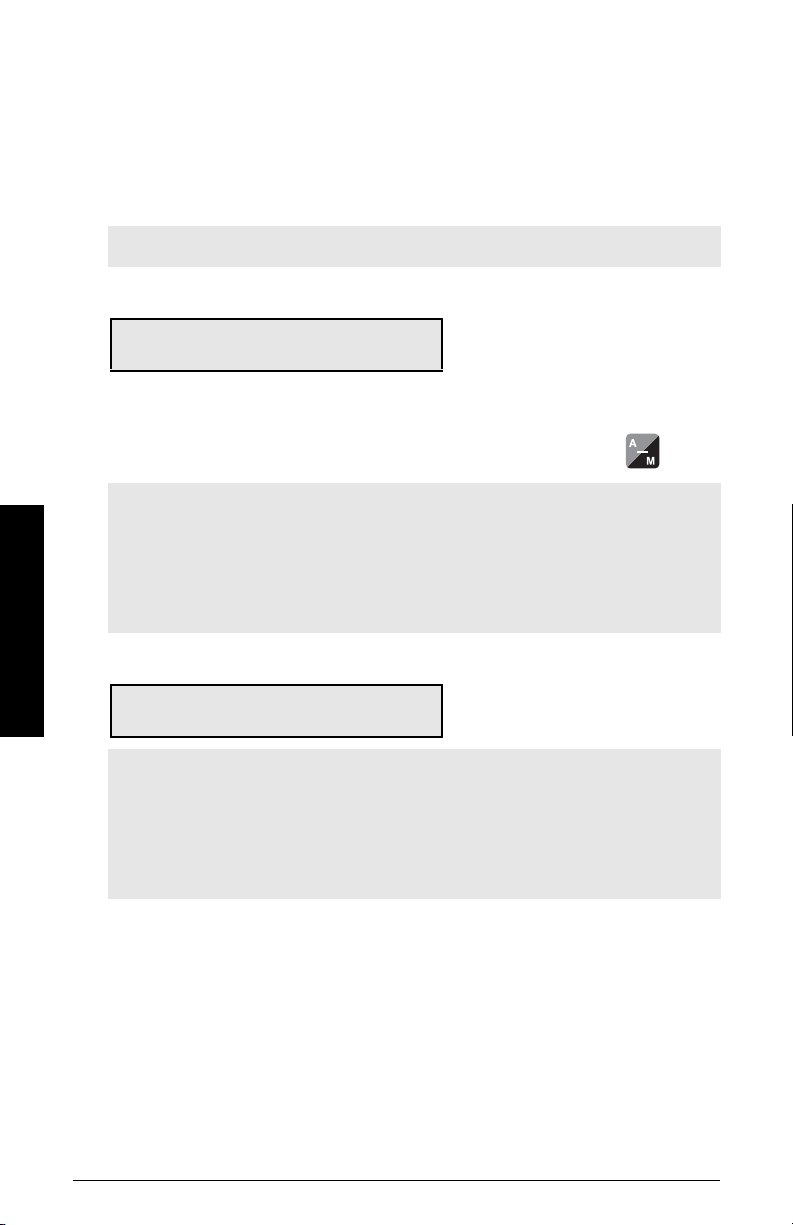
Programming
The BW500 is software ready, however the controller function must be specifically
programmed in addition to programming of parameters P001 through P017.
The BW500 offers programming for two separate PID controls, 1 and 2. The controller
being programmed is identified by the suffix to the parameter number. e.g. P400-01
indicates that PID for control system 1 is accessed.
Note: All programming should be done in the PID manual mode.
Access
P400-01 PID System E
Select: 0-Off, 1-Manual, 2-Auto 0
Off disables the PID parameter set, P401 to P418. They are not accessible.
Manual: the control output is the manual output P410.
Auto: engages the PID controller function. This can also be done using the key.
select 1-manual to program PID parameters
Note:
For the mA output:
• mA output 2 (P201-02) is normally reserved for controller 1. The signal is
output at terminals 1 and 2 on the mA I/O board.
• mA output 3 (P201-03) is normally reserved for controller 2. The signal is
output at terminals 3 and 4 on the mA I/O board.
PID Control
P201-02 mA Output Function E
Select: 1-Rate, 2-Load, 3-Speed, 4-PID 1
select the PID function
Note:
For the mA input:
• mA input 1 is an external signal normally reserved for controller 1. The
signal is input at terminals 5 and 6 on the mA I/O board.
• mA input 2 is an external signal normally reserved for controller 2. The
signal is input at terminals 7 and 8 on the mA I/O board.
Page 80 Milltronics BW500 and BW500/L - OPERATING INSTRUCTIONS 7ML19985DK05
Page 87
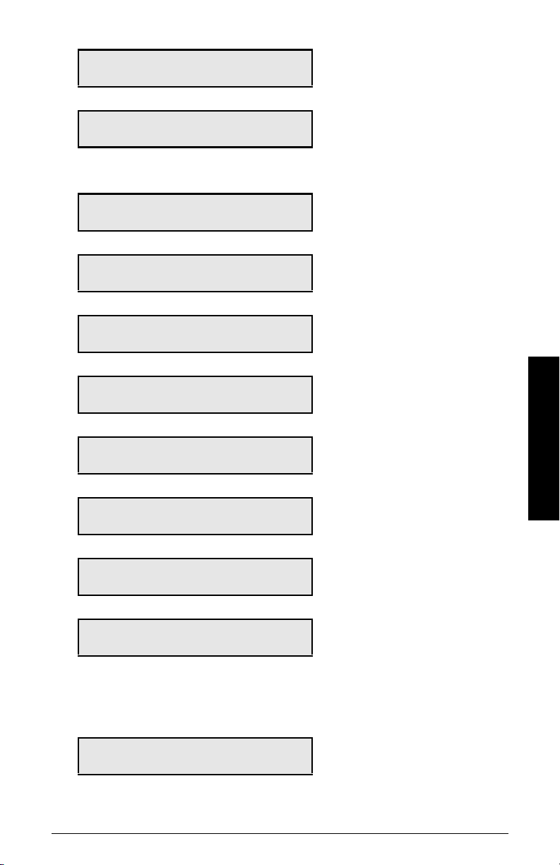
P250-01 mA Input Range E
Select 1- 0 to 20, 2-4 to 20 2
select the appropriate range for the mA
input signal
P255-01 mA Input Function E
Select: 0, 1-PID SP, 2-PID PV 0
P401-01 PID Update Time E
Readings between PID Updates 1
P402 Process Variable Source E
1-Rate, 2-Load, 3-mA In
P405-01 Proportional Term E
Enter 0.40
P406-01 Integral Term E
Select 1- 0 to 20, 2-4 to 20 0.2
P407-01 Derivative Term E
Enter 0.05
P408-01 Feed Forward Term E
Enter 0.3
assign either:
1: PID setpoint, or
2: process variable as the function of the
mA input
enter the value, e.g. nominal value of 1
select the source. Rate and load are internal values.
enter the value for the proportional term,
e.g. nominal value of 0.4
enter the value for the integral term, e.g.
nominal value of 0.2
enter the value for the derivative term, e.g.
nominal value of 0.05
enter the value for the feed forward term,
e.g. nominal value of 0.3
PID Control
P410-01 Manual Mode Output E
Current Output Value 0
P414-01 Setpoint Configuration E
0-Local, 1mA In 0
% value of output during manual operation, P400 = 1
selection of setpoint source:
0 = local (keypad or Dolphin Plus)
1 = mA input
Local: the setpoint is the value entered into P415
mA Input 1: the setpoint is the mA value on input 1, terminals 5 and 6 on the mA I/O board
mA Input 2: the setpoint is the mA value on input 2, terminals 7 and 8 on the mA I/O board
P415-01 Local Setpoint Value E
Enter Setpoint 0
enter the setpoint value in engineering
units.
Not applicable if P414 = 1
7ML19985DK05Milltronics BW500 and BW500/L - OPERATING INSTRUCTIONS Page 81
Page 88
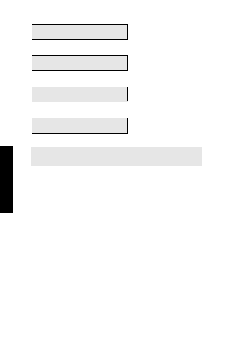
P416-01 External Setpoint E
Setpoint 0
current setpoint value in engineering units,
obtained from the mA input
P418-01 Remote Setpoint Ratio V
Enter % of Master Output 100.000
P250-01 mA Input Range E
Select 1- 0 to 20, 2-4 to 20 2
P255-01 mA Input Function E
Select 0, 1-PID SP, 2-PID PV 0
increase or decrease to scale input setpoint, if desired.
select the appropriate range for the mA
input signal
assign either:
1: PID setpoint, or
2: process variable as the function of the
mA input
Note: The PID setpoint can be modified while in RUN mode using the up/down
arrow keys.
PID Control
Page 82 Milltronics BW500 and BW500/L - OPERATING INSTRUCTIONS 7ML19985DK05
Page 89

Batching
1)
The batching process, as it relates to the BW500 operation, can be defined as the transfer
of a predetermined quantity of material.
The process supports a count up operation (P560), in that the total (totalizer 5) begins at
zero and increments up to the programmed setpoint (P564). A relay (RL1 through 5)
programmed as the batch setpoint function (P100 = 8) is actuated when the material total
reaches the setpoint. The relay contact acts as an interlock to the material feed to end
the batch.
Another relay can be programmed as a pre-warn alarm (P100 = 7), to alert the process
that batch end is near. The relay is actuated when the material total reaches the prewarn setpoint (P567) at some practical value below the batch setpoint. The pre-warn
function is enabled/disabled from the batch process through P566.
For batch operations, the following must be addressed:
• connections
• programming
•operation
1)
Not available on the BW500/L
7ML19985DK05Milltronics BW500 and BW500/L - OPERATING INSTRUCTIONS Page 83
Batching
Page 90
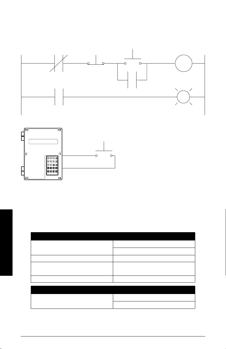
Connections
BW500 / RL1*
batch stop
47 48
49
50
24
29
stop
start
motor contactor /
MC1
alarm
MC1
BW500 / RL2*
pre-warm
BW500/
aux 1
batch reset
* Typical relay assignment. Relays 1-5 are
available for batch setpoint or pre-warm alarm
function.
Typical auxiliary input assignment. Inputs 1- 5
are available for batch reset.
Typical Ladder Logic
Programming
The pre-warn function is optional.
The setpoint associated with the pre-warn relay is entered in P564, batch setpoint.
The setpoint associated with the batch relay is entered in P567, batch pre-warn setpoint.
Batch Operation
Batching
access P100, relay function
Access P560 Batch Mode Control select 1, enable batch operation
if batch pre-warn is selected
select relay (1 – 5)
select function 7, pre-warn
enter the pre-warn total
access P567, batch pre-warn setpoint
Access P568 Batch Pre-act set to OFF (0) or AUTO (1) or manual (2)
Relays
Access P100, Relay Function
Page 84 Milltronics BW500 and BW500/L - OPERATING INSTRUCTIONS 7ML19985DK05
select relay (1 – 5)
select function 7, Pre-Warn
Page 91
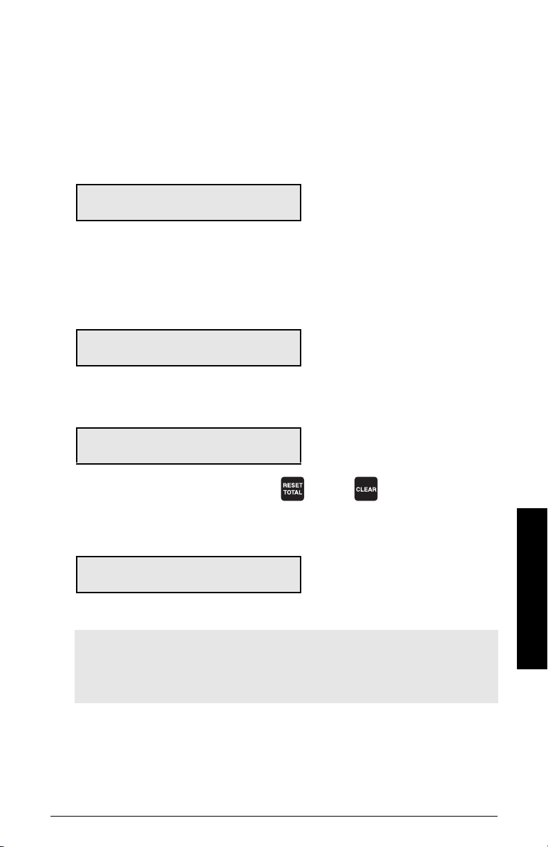
Operation
Once the BW500 relays are connected to the process logic, and it is programmed, the
BW500 is ready for totalizing the batch and stopping the process when the batch setpoint
is reached. The batch operation: start, pause, resume, and cancel are controlled
externally by the process control (e.g. PLC)
Place the unit in the RUN mode.
Press ALT DISP until the batch screen is displayed.
Rate 0.00 kg/h SP: 20.000
Batch 0.00 kg
Start running the batch.
The display will show the rate of material flow and the batch total, as well as the batch
setpoint. If pre-warn is used, relay contact is open.
When the batch total reaches the pre-warn setpoint, if programmed, the alarm event is
removed and the assigned relay contact is closed.
Rate 123.4 kg/h SP: 20.000
Batch 17.00 kg ALM 1
The process continues, and when the batch total reaches the batch setpoint, the alarm
event is displayed and the assigned relay is actuated (contact opened). Typically the relay
contact would be integrated into the batch control logic to end the process.
Rate 123.4 kg/h
Batch 20.00 kg ALM 12
When the next batch is to be run, pressing
providing a momentary contact closure across an auxiliary input (programmed as batch
reset, P270 = 8), sets the alarm display and resets the batch total to zero, and the relay
contact to its closed state.
Rate 0.00 kg/h SP: 20.000
Batch 0.00 kg
e.g relay 1 is programmed for pre-warn,
P100-1=7
e.g. relay 2 is programmed for batch setpoint, P100-2=8
and then on the local keypad, or
Batching
Note:
• The batch totalizer can be viewed as a read-only parameter (931-05), using single
Parameter access through any programmed communication port.
• The batch setpoint can be modified in RUN mode using the up/down arrow keys.
Pre-act Function
If repetitive batches are being run, the pre-act function (P568) can be enabled to
automatically trip the setpoint relay before or after the batch setpoint is reached to
assure best batch accuracy.
7ML19985DK05Milltronics BW500 and BW500/L - OPERATING INSTRUCTIONS Page 85
Page 92
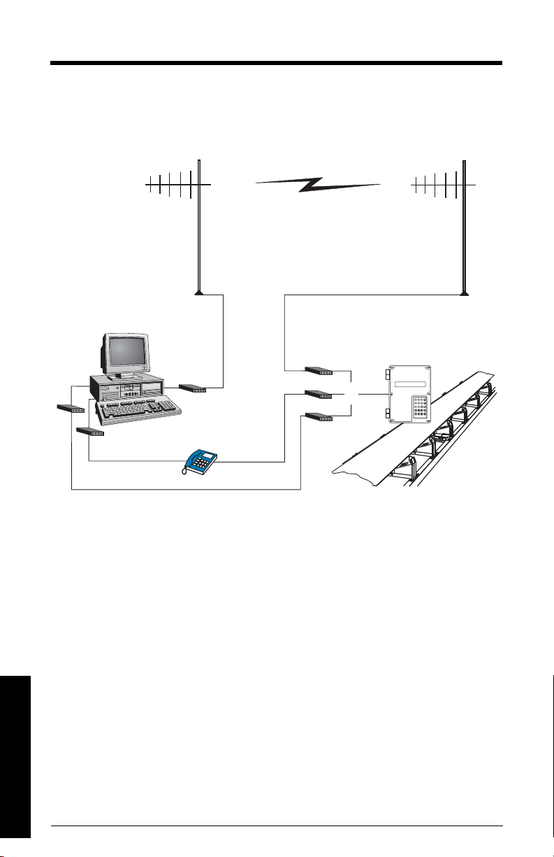
Communications
radio modem
or
dial-up modem
leased line modem
The BW500 and BW500/L is an sophisticated belt scale integrator that can communicate
status back to a SCADA system using a serial device such as radio modems, leased lines,
or dial up modems.
The BW500 and BW500/L supports two protocols: Dolphin and Modbus. Dolphin is a
proprietary Siemens Milltronics protocol designed to be used with Dolphin Plus. Modbus
is an industry standard protocol used by popular SCADA and HMI systems.
Communications
Page 86 Milltronics BW500 and BW500/L - OPERATING INSTRUCTIONS 7ML19985DK05
Page 93
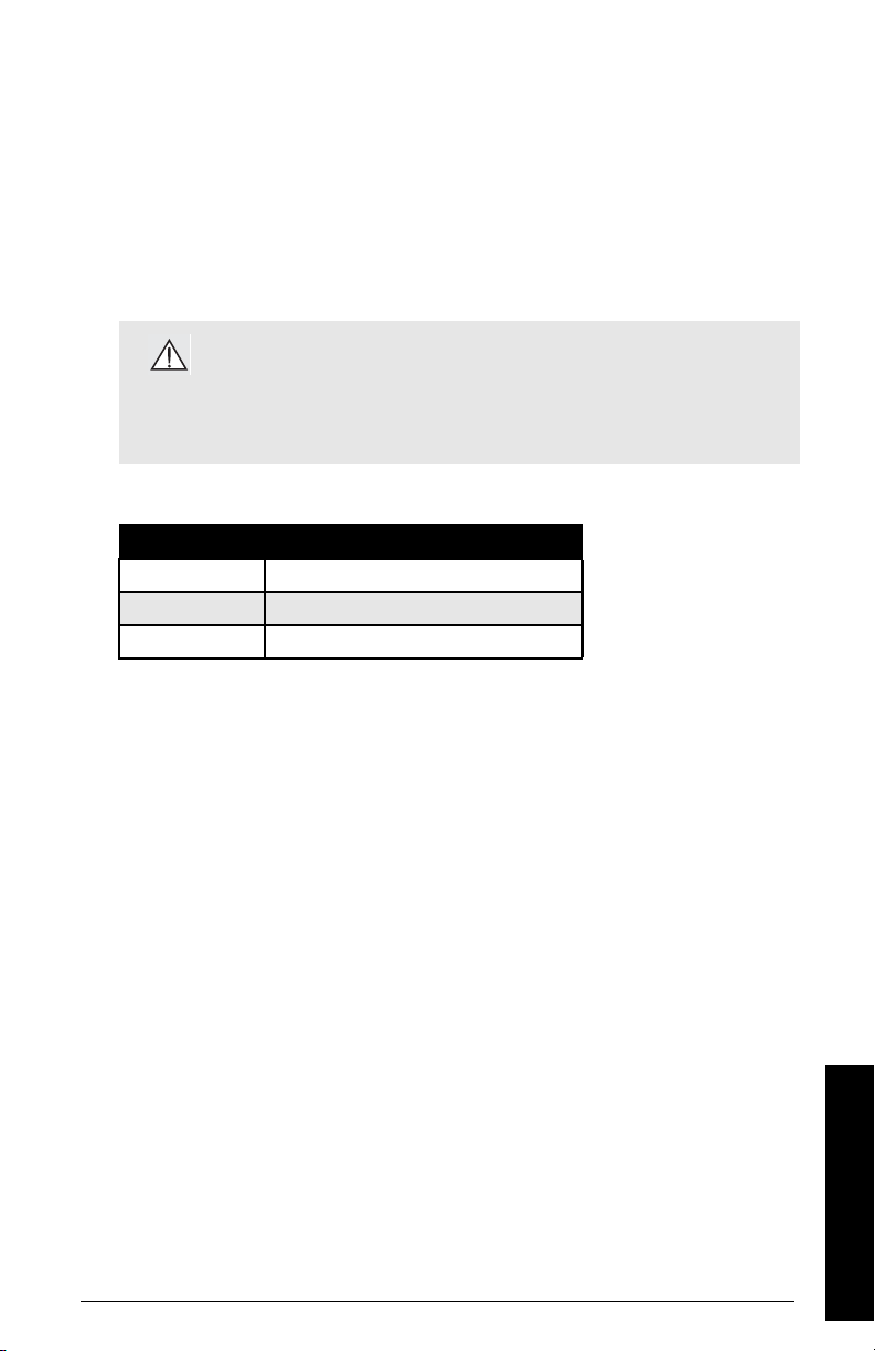
BW500 and BW500/L and SmartLinx®
In addition to three onboard communication ports, the BW500 and BW500/L is compatible
with Siemens’ SmartLinx®
popular industrial communication systems.
This section only describes the onboard communications. For more information on
SmartLinx®, please consult the appropriate SmartLinx® manual.
communication modules which provide an interface to
Connection
WARNING: When a SmartLinx® card is installed and P799 = 1,
the parameters that the SmartLinx® card is writing to the BW500
and BW500/L will be continuously updated. Therefore, if you
connect a SmartLinx®
write anything to the SmartLinx® card, your setpoints will be 0.
There are three serial communication ports on the BW500 and BW500/L:
Port Description
1
2
3
Refer to the
RS-232, Terminals 31 to 34
RS-485, terminals 41 to 46
RS-232, RJ-11 modular telephone jack
Installation
on page 9 for wiring diagrams specific to each port.
Wiring Guidelines
card to the BW500, set P799 = 1 and not
Improper wiring and choice of cables are the most common sources of communication
problems. Listed below are some suggested guidelines:
• 15 meters (50 feet) for RS-232
• 1200 meters (4000 feet) for RS-485
• Ensure that communication cable is run separately from power and control cables
(i.e. do not tie wrap your RS-232 cable to the power cable or have them in the same
conduit).
• cable is shielded and connected to ground at one end only
• 24 AWG (minimum)
• follow proper grounding guidelines for all devices on the bus
• use good quality communication grade (shielded twisted pairs) cable that is
recommended for RS-232.
7ML19985DK05Milltronics BW500 and BW500/L - OPERATING INSTRUCTIONS Page 87
Communications
Page 94
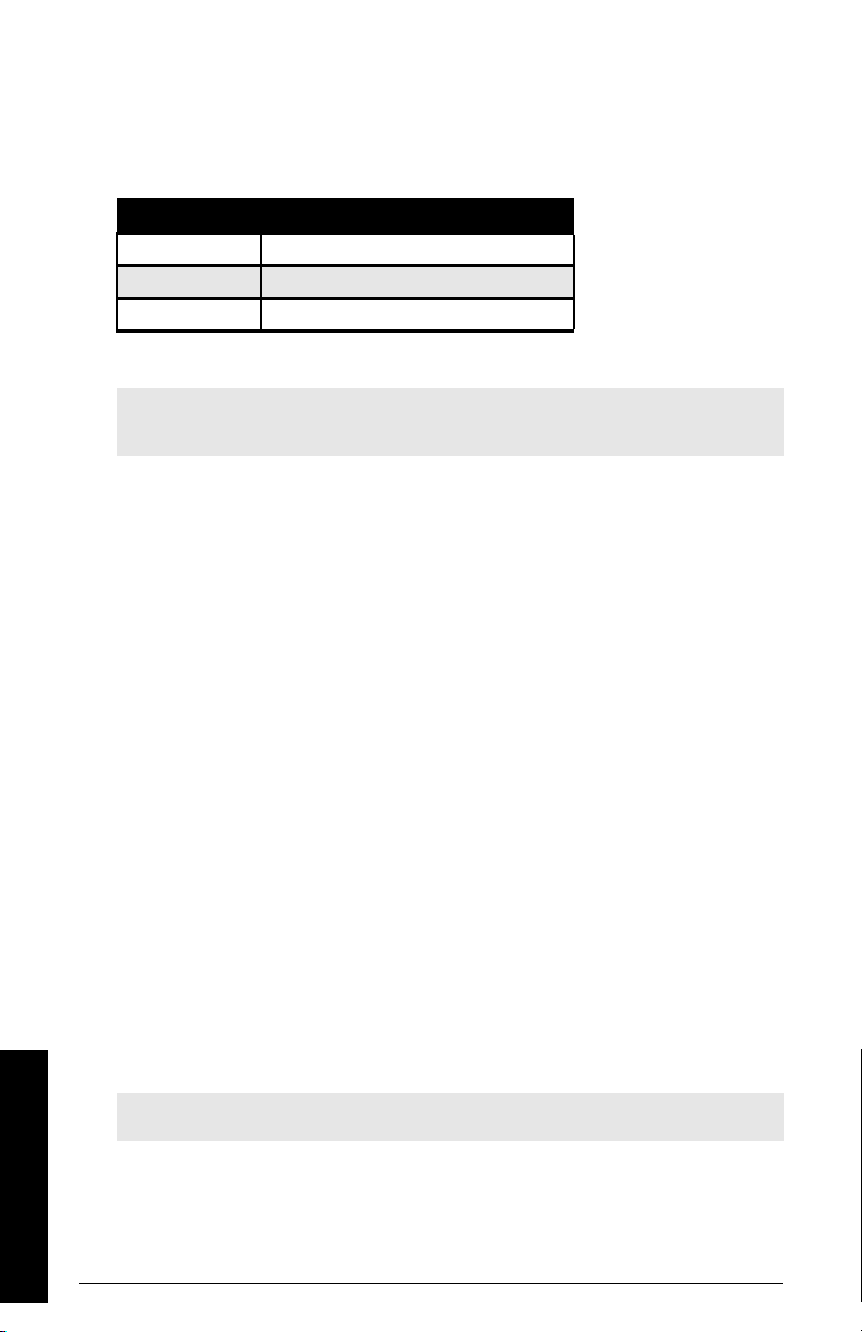
Configuring Communication Ports
The BW500 and BW500/L communications ports are setup by a series of parameters
(P770 – P789) which are indexed by port.
The communication parameters are indexed to the following:
Port Description
1
2
3
f
indicates the factory setting.
Note: Changes to these parameters are not effected until the power to the unit is
turned off and then back on.
P770 Serial protocols
The communications protocol used between the BW500 and BW500/L and other devices
for the selected port, ports 1 to 3 (P770-01 to –03).
The BW500 and BW500/L supports Siemens Milltronics’ proprietary “Dolphin” data
format, as well as the internationally recognized Modbus standard in both ASCII and RTU
formats. It also supports direct connection of a printer.
The Siemens protocol is compatible with the Dolphin Plus configuration program. See the
Siemens web site for information on this PC product
(http://www.siemens.com/processautomation).
The Modbus protocol is an open standard developed by AEG Schneider Automation Inc.
Specifications are available from their web site (http://www.modicon.com/).
Other protocols are available with optional SmartLinx®
Val ues
f (01 and 02)
0
f (03)
1
2 Modbus ASCII slave serial protocol
3 Modbus RTU slave serial protocol
4printer
RS-232, Terminals 31 to 33
RS-485, terminals 41 to 45
RS-232, RJ-11 modular telephone
communications disabled
Siemens Milltronics "Dolphin" protocol
cards.
Note: BW500 and BW500/L must be in RUN mode to allow for the print operation.
Communications
Page 88 Milltronics BW500 and BW500/L - OPERATING INSTRUCTIONS 7ML19985DK05
Page 95

P771 Protocol address
Note: Applicable only to ports programmed for Modbus RTU or Modbus ASCII (P770).
The unique identifier of the BW500 and BW500/L on the network for the selected port,
ports 1 to 3 (P771-01 to -03).
For devices connected with the Siemens Milltronics protocol this parameter is ignored.
For devices connected with a serial Modbus protocol this parameter is a number from 1-
247. It is up to the network administrator to ensure that all devices on the network have
unique addresses.
Do not use the value “0” for Modbus communications as this is the broadcast address
and is inappropriate for a slave device.
Values
0 to 9999 (f = 1)
P772 Baud Rate
The communication rate with the master device for the selected port, ports 1 to 3 (P77201 to –03).
The baud rate chosen should reflect the speed of the connected hardware and protocol
used.
Values
f (01 and 02)
1
2 9600 baud
f (03)
3
4800 baud
19,200 baud
P773 Parity
The serial port parity for the selected port, ports 1 to 3 (P773-01 to –03).
Ensure that the communications parameters are identical between the BW500 and
BW500/L and all connected devices.
For example many modems default to N-8-1 which is: No parity, 8 data bits, and 1 stop bit.
Values
f
0
none
1even
2odd
7ML19985DK05Milltronics BW500 and BW500/L - OPERATING INSTRUCTIONS Page 89
Communications
Page 96

P774 Data bits
The number of data bits per character for the selected port, ports 1 to 3 (P774-01 to –03).:
Protocol P744 Value
Modbus RTU
Modbus ASCII
Dolphin Plus
8
7 or 8
7 or 8
Note: If using port 2, 8 data bits must be used.
Values
5 to 8 (f = 8)
P775 Stop bits
The number of bits between the data bits for the selected port, ports 1 to 3
P775-01 to -03).
Values
1 or 2 (f = 1)
P778 Modem attached
Sets port 1 (P778-01) to use an external modem.
Any connected modem must be set up to auto-answer incoming calls. The BW500 and
BW500/L does not automatically configure the modem.
Autobaud (enabled by P778=1)
When the BW500 and BW500/L is powered up or the P779 Modem Inactivity Timeout
expires three carriage returns are sent to the modem to allow it to set its serial
connection to P772 Baud Rate.
If a connection is made with the modem at a different baud rate the BW500 and BW500/L
will attempt to use that rate instead of the P772 value. For troubleshooting purposes the
baud rate on the modem can be hard-coded to the rate set on the BW500 and BW500/L.
See your modem documentation for information on fixing the baud rate.
Values
f
no modem connected
0
1 modem connected
Communications
Page 90 Milltronics BW500 and BW500/L - OPERATING INSTRUCTIONS 7ML19985DK05
Page 97

P779 Modem idle time
Sets the time in seconds that the BW500 and BW500/L will keep the modem connected
even though no activity is happening.
To use this parameter ensure that P778=1.
This parameter allows for reconnection to the BW500 and BW500/L unit after an
unexpected disconnect. Ensure that the value is low enough to avoid unnecessary delays
when an unexpected disconnect occurs but long enough to avoid timeout while you are
still legitimately connected.
Hanging Up
If the line is idle and the P779 Modem Inactivity Timeout expires then the modem is
directed to hang up the line. This is done with the Hayes commands:
• two second delay
• +++
• two second delay
•ATH
Ensure that P779 is set longer than the standard polling time of the connected master
device.
0 disables the inactivity timer.
Values
0-9999: 0 (f = 1)
P780 RS-232 Transmission interval
Note: Applicable only to ports programmed for printer communication
(P770).
Sets the interval between transmissions to be applied to the selected port, ports 1 to 3
(P780-01 to –03).
Enter the period in minutes (
7ML19985DK05Milltronics BW500 and BW500/L - OPERATING INSTRUCTIONS Page 91
f
= 0)
Communications
Page 98

P781 Data message
Note: Applicable only to ports programmed for printer communication (P770).
Sets the data message to be delivered via the selected port, ports 1 to 3 (P781-01 to -03).
All messages and printouts include time and date.
Entry:
0f = no message
1 = rate
1)
2 = total
3 = load
4 = speed
5 = rate, total
6 = rate and total
7 = batching
8 = rate and speed
9 = quick start parameters (P001 – P017)
10 = all parameters
1)
, load and speed
1)
2)
P799 Communications Control
Assigns programming control either locally through the keypad or Dolphin Plus (P770 = 1),
or remotely through Modbus protocol (P770 = 2 or 3) or SmartLinx®
.
Entry:
0 = local
1 = remote
WARNING: When a SmartLinx® card is installed and P799 = 1,
the parameters that the SmarlLinx® card is writing to the BW500
and BW500/L will be continuously updated. Therefore, if you
connect a SmartLinx® card to the BW500 and BW500/L, set P799
= 1 and not write anything to the SmarLinx® card, your setpoints
will be 0.
1)
Totalizer 1 and/or 2 as set by P647, Totalizer Display.
Communications
2)
Not available with BW500/L
Page 92 Milltronics BW500 and BW500/L - OPERATING INSTRUCTIONS 7ML19985DK05
Page 99
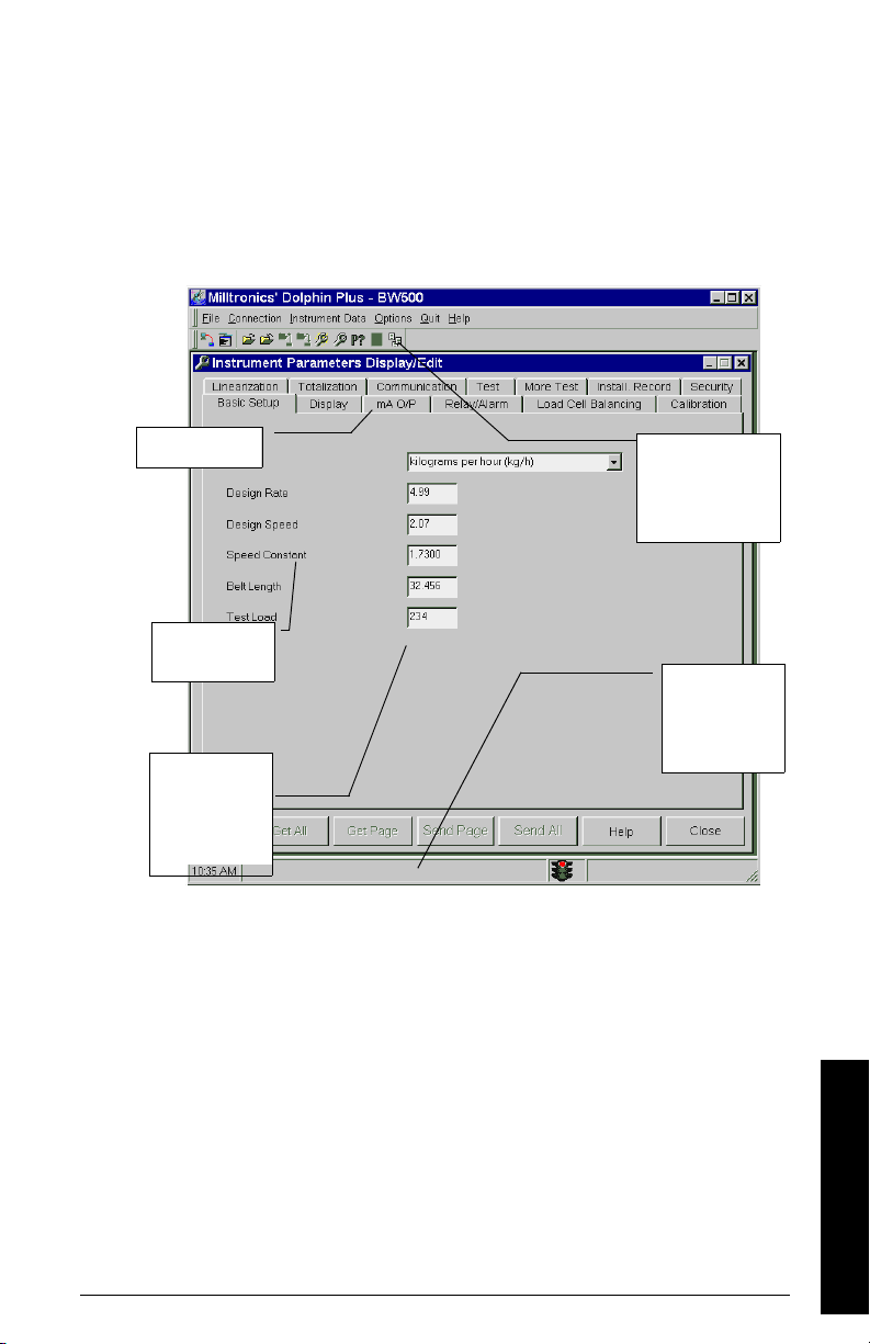
Dolphin Protocol
Tabs show groups
of parameters
Param ete rs ca n
be tracked while
the BW500 and
BW500/L is
running
The status bar
informs you of
program actions
and data transfer
status
The attached device
can be programmed,
debugged, and
monitored from
Dolphin Plus
Param ete rs have
roll-overs which
show number
The protocol is available on all communications ports on all units. This protocol is not
available for third party use.
The primary use of this protocol is to connect the BW500 and BW500/L to Siemens
Milltronics’ Dolphin Plus configuration software.
Dolphin Plus Screen Shot
7ML19985DK05Milltronics BW500 and BW500/L - OPERATING INSTRUCTIONS Page 93
Communications
Page 100

Modbus RTU/ASCII Protocol
Modbus is an industry standard protocol owned by Schneider Automation Inc.1) and is
used throughout process control industries for communication between devices. Modbus
RTU and Modbus ASCII are both master-slave type protocols. BW500 and BW500/L’s
Modbus is a slave unit.
BW500 and BW500/L supports both the RTU and ASCII version of Modbus and attempts
to automatically detect the type when a connection is made.
Note:
• host should wait at least 500 ms between a message polls to the BW500 and
BW500/L
• for Modbus RTU, the host should wait at least 1000 ms for a response from the
BW500 and BW500/L. In Modbus ASCII mode the suggested timeout is 1500 ms.
A brief description of Modbus RTU and Modbus ASCII is given in this manual. For a full
description of the Modbus protocol, contact your local Schneider representative. Also
you may try their web site at:
http://www.modicon.com
At the time of publication of this manual, the Modbus Protocol was located under
products / technical publications / communications products / Modbus protocol.
Note: Siemens does not own the Modbus RTU protocol. All information regarding
that protocol is subject to change without notice.
How Modbus Works
As mentioned above, Modbus is a master-slave type protocol. This can also be referred to
as a query-response protocol. What both of these terms mean is that on the network,
there is one master which requests information from multiple slave devices. The slave
devices are not permitted to talk unless they have been asked for information. When
responding, the slaves will either give the information that the master has requested or
give an error code consisting of why it can not give the information or that it did not
understand the request. Refer to
All BW500 and BW500/L information is mapped into the Modbus holding registers so that
Modbus function code 03 can read from them and Modbus function code 06 and 16 can
write to them.
Communications
1)
Modicon is a registered trademark of Groupe Schneider.
Page 94 Milltronics BW500 and BW500/L - OPERATING INSTRUCTIONS 7ML19985DK05
Error Handling
on page 109.
 Loading...