

Page 1
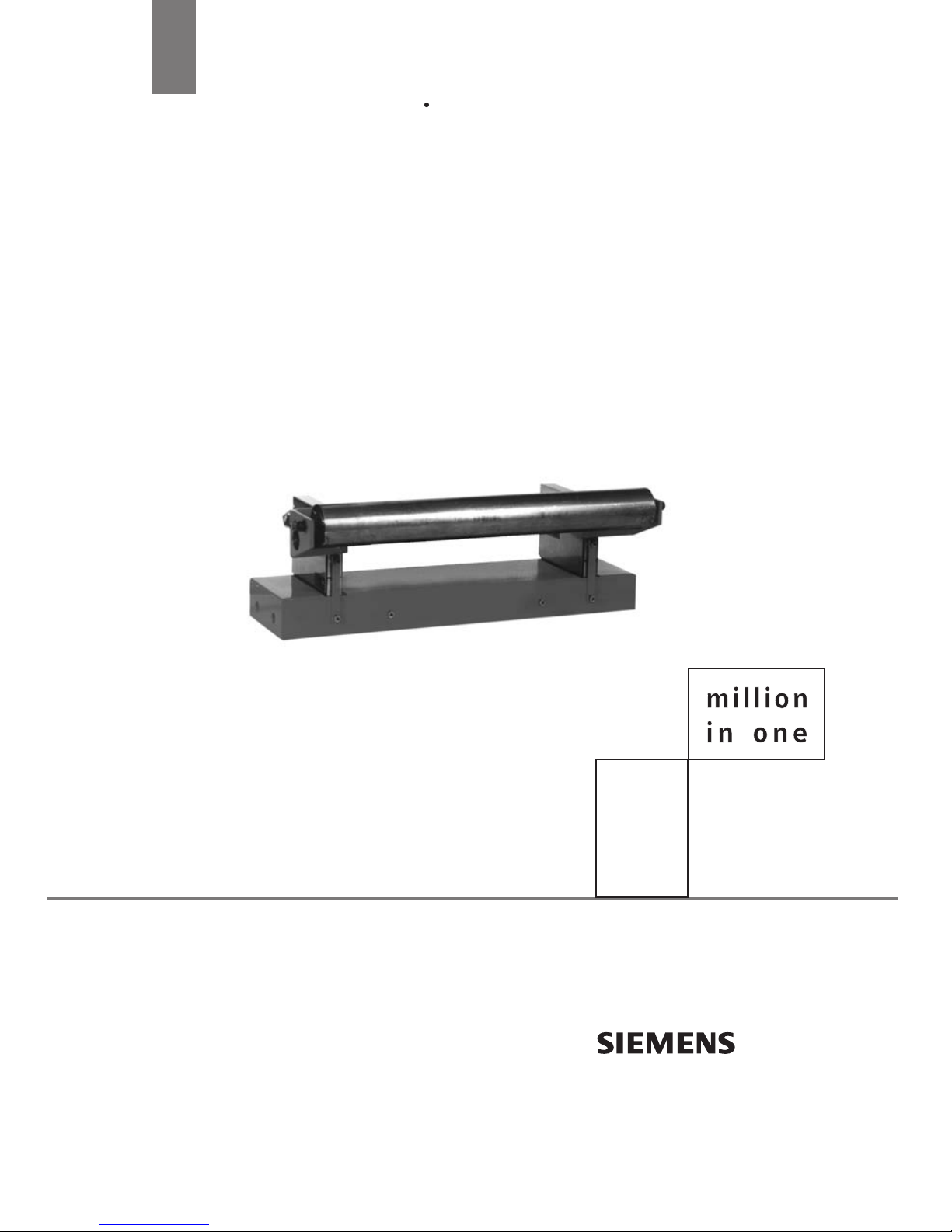
Instruction Manual May 2008
milltronics
MLC BELT SCALE
Page 2

Safety Guidelines: Warning notices must be observed to ensure personal safety as well as that of
others, and to protect the product and the connected equipment. These warning notices are
accompanied by a clarification of the level of caution to be observed.
Qualified Personnel: This device/system may only be set up and operated in conjunction with this
manual. Qualified personnel are only authorized to install and operate this equipment in accordance with
established safety practices and standards.
Unit Repair and Excluded Liability:
• The user is responsible for all changes and repairs made to the device by the user or the user’s
agent.
• All new components are to be provided by Siemens Milltronics Process Instruments Inc.
• Restrict repair to faulty components only.
• Do not reuse faulty components.
Warning: This product can only function properly and safely if it is correctly transported, stored,
installed, set up, operated, and maintained.
This product is intended for use in industrial areas. Operation of this equipment in a residential area
may cause interference to several frequency based communications.
Note: Always use product in accordance with specifications.
Copyright Siemens Milltronics Process
Disclaimer of Liability
Instruments Inc. 2008. All Rights Reserved
This document is available in bound version and in
electronic version. We encourage users to purchase
authorized bound manuals, or to view electronic versions
as designed and authored by Siemens Milltronics Process
Instruments Inc. Siemens Milltronics Process Instruments
Inc. will not be responsible for the contents of partial or
whole reproductions of either bound or electronic
versions.
While we have verified the contents of this
manual for agreement with the
instrumentation described, variations
remain possible. Thus we cannot
guarantee full agreement. The contents of
this manual are regularly reviewed and
corrections are included in subsequent
editions. We welcome all suggestions for
improvement.
Technical data subject to change.
MILLTRONICS®is a registered trademark of Siemens Milltronics Process Instruments Inc.
Contact SMPI Technical Publications European Authorized Representative
at the following address:
Technical Publications Siemens AG
Siemens Milltronics Process Instruments Inc. Industry Sector
1954 Technology Drive, P.O. Box 4225 76181 Karlsruhe
Peterborough, Ontario, Canada, K9J 7B1 Deutschland
Email: [email protected]
• For a selection of Siemens Milltronics level measurement manuals, go to:
www. siemens.com/processautomation. Under Process Instrumentation, select
Measurement
• For a selection of Siemens Milltronics weighing manuals, go to:
www. siemens.com/processautomation. Under Weighing Technology, select
Weighing Systems
and then go to the manual archive listed under the product family.
and then go to the manual archive listed under the product family.
Level
Continuous
© Siemens Milltronics Process Instruments Inc. 2008
Page 3

Table of Contents
Introduction ..........................................................................................................................1
The Manual ...............................................................................................................................................1
Milltronics MLC Belt Scale ...................................................................................................................1
Specifications ......................................................................................................................2
Operation ..............................................................................................................................3
Installation ........................................................................................................................... 3
Welding ......................................................................................................................................................4
Load Cell Handling ..................................................................................................................................4
Installation Precautions .........................................................................................................................4
Installation Procedure ............................................................................................................................5
Idler Alignment .........................................................................................................................................6
Alignment Procedure ....................................................................................................................6
Calibration ............................................................................................................................8
General .......................................................................................................................................................8
Test Load ...................................................................................................................................................8
Zero .............................................................................................................................................................8
Span ............................................................................................................................................................8
Maintenance ........................................................................................................................9
Spare Parts ...............................................................................................................................................9
Wiring ..................................................................................................................................10
Dimensions ........................................................................................................................11
Installation .....................................................................................................................................11
i
Page 4

ii
Page 5

Introduction
The Manual
Note:
• Please follow the installation and operating procedures for a quick, trouble-free
installation, and to ensure the maximum accuracy and reliability of your Siemens
Milltronics weighing system.
• The MLC is to be used only in the manner outlined in this manual or protection
provided to the equipment may be impaired.
• This product is intended for use in industrial areas. Operation of this equipment in
a residential area may cause interference to several frequency based
communications.
The Milltronics MLC belt scale is used in conjunction with the selected integrator and
speed sensor. This manual covers only MLC installation and operating procedures.
Integrator and speed sensor instruction manuals can be downloaded from
www. siemens.com/continuous-weighing
.
This manual will help you set up your MLC for optimum performance. We always
welcome suggestions and comments about manual content, design, and accessibility.
Please direct your comments to [email protected]
.
Milltronics MLC Belt Scale
Milltronics MLC belt scale is a low-capacity scale for light belt loading. It is designed to
be inserted into either a flat roll idler (non-troughing) belt conveyor or a flat pan slider belt
conveyor for continuous weighing of dry bulk solids. The MLC is suitable for monitoring
such products as fertilizer, tobacco, animal feed pellets, and sugar.
The MLC belt scale consists of the following:
• a static beam (125 mm [5"] steel channel support frame)
• two precision load cells (Each cell lead wire is run in flexible conduit, with
approximately 1 m [3.28 ft] extending beyond the static beam)
• a flat roll idler
• a calibrating test rod, 22 mm (7/8") diameter
• a 25.4 mm (1") OD tube (to house the calibrating test rod)
• two mounting brackets (supports the idler, tube, and rod on the load cells)
• two shipping stops
The MLC load cells output an electrical signal proportional to load, which is applied to the
selected Siemens Milltronics belt scale integrator. Thus, weighing is accomplished
without interrupting the process and without affecting the process material.
Important: The MLC belt scale is an accurate and repeatable force sensor. Its
performance is ultimately dependent upon the conveyor system and the quality of the
installation and accuracy of the alignment.
7ML19985FF01 Milltronics MLC Belt Scale – INSTRUCTION MANUAL Page 1
Page 6

Specifications
Accuracy
• ±1.0% of totalization over 5 to 1 operating range
Belt Width
• metric: 450 to 1200 mm
• imperial: 18 to 48"
Belt Speed
• 2.0 m/s (400 fpm) maximum
Capacity
• up to 50 t/h (depending on loading and belt speed parameters)
Conveyor Incline
• ±20º from horizontal, fixed incline
• up to ±30º with reduced accuracy
Conveyor Idler Profile
•horizontal
Idler Diameter
• metric: 50 or 60 mm
• imperial: 1.90"
Idler Spacing
• 0.5 to 1.5 m (1.5 to 5 ft)
Loading
• Minimum 1.0 kg/m (0.6 lbs/ft)
• Maximum 30 kg/m (20 lbs/ft)
Load Cell
• excitation: 10 V DC nominal, 15 V DC maximum
• output: 2 mV/V excitation at rated load cell capacity
• non-linearity: 0.03% of rated output
• hysteresis: 0.05% of rated output
• non-repeatability: 0.03% of rated output
• capacity: 10 or 20 lbs.
• overload: safe 150% of rated capacity, ultimate 300% of rated capacity
•temperature:
-40 to 85ºC (-40 to 185ºF) operating range
-10 to 60ºC (14 to 140ºF) compensated
• stainless steel construction
• mounting dimensions: identical for all capacities
Hazardous Locations
• with the use of approved intrinsically safe barrier strips
Approvals
1
•CE
1.
EMC performance available upon request.
Page 2 Milltronics MLC Belt Scale – INSTRUCTION MANUAL 7ML19985FF01
Page 7

Operation
The MLC belt scale works with an existing light-duty flat belt conveyor (handling lightdensity materials) and the selected Siemens Milltronics integrator. As material moving
along the conveyor belt travels over the belt scale, it exerts a force proportional to the
material load through the suspended idler to the load cells.
The MLC reacts only to the vertical component of the applied force. The resulting
movement in each load cell is sensed by its strain gauges. When the strain gauges are
excited by voltage from the electronic integrator, they produce an electrical signal
proportional to weight, which is then applied to the integrator. The vertical movement of
the load cells is limited by the positive overload stop incorporated into the design of the
load cell.
Installation
The MLC belt scale is shipped from the factory as a single unit in a heavy-duty shipping
container. The container is packed to separate each item and to provide protection during
shipment. Each item should be inspected as it is removed from the container.
Notes: Be sure the conveyor design meets the installation requirements for the
Siemens Milltronics MLC belt scale.
• Adjust conveyor stringers to be rigid, straight, parallel to, and square with
the belt line in the area of the scale installation.
• Adjust pulleys to ensure that the conveyor belt tracks straight and centrally
from the head to the tail pulley.
To limit the weight and dimensions of the idler on the scale, Siemens Milltronics provides
an idler built to definite specifications as part of the scale. If a substitute or a replacement
is required, please contact Siemens. Substituting or replacing this idler with a non-spec
idler could result in damage to the scale due to overloading or improper fit.
To avoid potential scale installation problems, please compare the site conditions with
the MLC installation drawings available on www.siemens.com/continuous-weighing
you have any questions, please contact your Siemens representative.
. If
7ML19985FF01 Milltronics MLC Belt Scale – INSTRUCTION MANUAL Page 3
Page 8

Welding
WARNING:: Extreme care should be used when arc welding in the area of
the belt scale. Ensure that no welding current can flow through the belt scale.
Welding currents passing through the scale can functionally damage the load
cells.
Load Cell Handling
The MLC belt scale is designed for low-capacity operation and is constructed using two
10 or 20 pound load cells. Although the load cells are protected by shipping stops that
keep the cells from moving, care should be taken when handling the scale to avoid
damaging the cells. The stops are metal strips about 75 mm (3") long with holes at each
end for screws. One screw holds the stop to the load cell while the other screw holds the
stop to the static beam (125 mm [5"] channel).
When handling the MLC during installation and set-up, make sure the stops remain in
place.
Reinstall both shipping stops during maintenance or prolonged shutdown.
Installation Precautions
The following precautions should be observed when handling the scale.
• Do not pry on the idler, its mountings, or the cells directly.
• Do not stand or lean on the scale.
• Avoid shock from blows of a hammer when trying to position the scale during
installation.
• Do not lift the MLC by its idler.
• Do not lift the MLC by the idler mounting brackets.
Page 4 Milltronics MLC Belt Scale – INSTRUCTION MANUAL 7ML19985FF01
Page 9
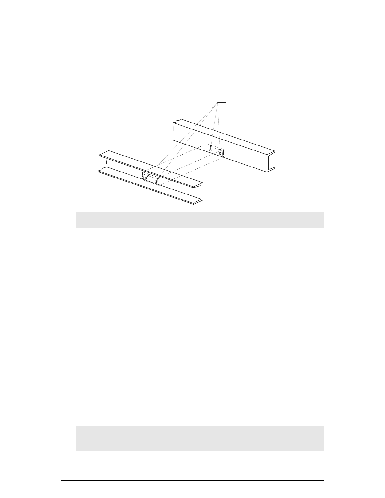
Installation Procedure
1. Make sure the shipping stops are in place and secure.
2. Remove the existing flat roll idler (or flat slider pan) from the area selected to locate
the belt scale assembly.
3. Drill four 12 mm (7/16") diameter mounting holes. This will allow clearance for 10 mm
(3/8") bolts.
12mm (7/16”)
(X 4)
Note: Slotting the holes vertically will permit greater adjustment capability.
4. Position the scale with the idler towards the head end of the conveyor and the static
beam toward the tail end.
• Make sure the belt travel sticker on the static beam points in the direction of belt
travel.
• Raise the conveyor belting to provide room for the installation of the scale.
5. Insert the scale (complete with the attached idler) into the conveyor.
• Insert four 10 mm (3/8") bolts through the conveyor frame and through the holes
in the ends of the static beam.
• Secure with hex nuts. Finger tight only.
6. Make sure there is at least 13 mm (1/2") of clearance between the return belt and the
MLC.
• In some conveyors, it may be necessary to install a return idler roller adjacent to
the scale to deflect the return belt past the scale.
7. Position the scale so that it is centered in the conveyor and square to the stringer.
• Shim as required between the ends of the static beam and the conveyor
stringer.
• Level the static beam and tighten the bolts sufficiently to keep the static beam in
place until final adjustment.
CAUTION: Off-center or off-square installation can result in poor belt tracking and
scale inaccuracy.
7ML19985FF01 Milltronics MLC Belt Scale – INSTRUCTION MANUAL Page 5
Page 10
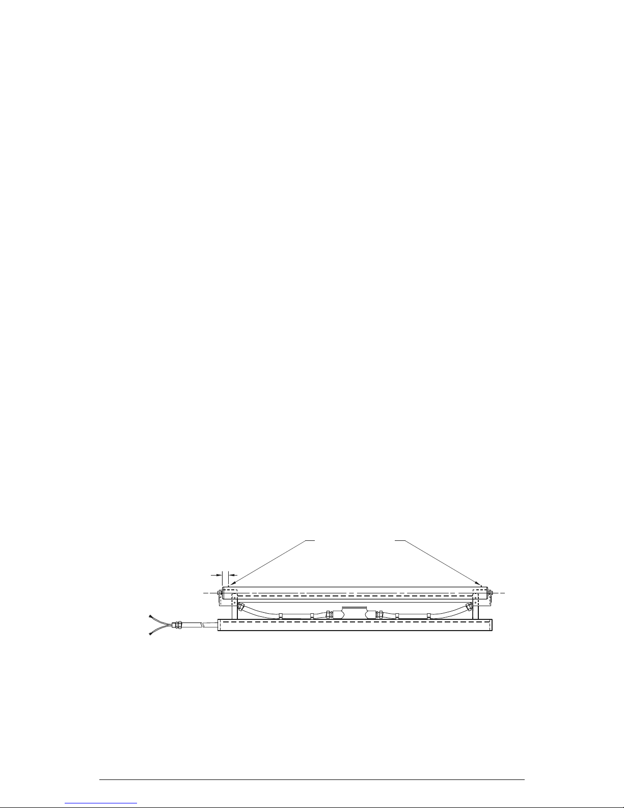
Idler Alignment
Precise alignment is very important to achieve maximum accuracy of the weighing
system. Improperly aligned idlers could cause unwanted forces to be applied to the
weighing idler, resulting in measurement errors.
Alignment Procedure
1. Remove the shipping stops to free the weighing mechanism.
• Keep the stops and screws stored in a convenient place for use during
maintenance or at other times when protection of the cells is necessary
2. Align and level the idler in the weighing area by raising or lowering the static beam
in its mountings.
• The weighing area includes the scale and at least one idler on each side of the
scale. For conventional flat idler roll conveyors, two additional idler rolls should
be included in the alignment procedure.
3. Adjust idlers (idlers and pans on a slider pan conveyor) vertically until they are all
within ±0.8 mm (1/32") of each other.
• Stretch a line across the top surface of each idler roll in the scale area at
approximately 25 mm (1") from each end of each idler roll.
• Use good quality wire (0.5 mm [0.020"] diameter) or equivalent nylon line to
check for alignment. The wire or string aligning lines must be able to withstand
sufficient tension to eliminate sag in the line.
.
4. Check that the idlers are centered and squared to the conveyor as in step 5 of the
installation procedure.
5. Tighten the static beam mounting bolts (34 to 40.8 Nm or 25 to 30 ft lbs).
6. Carefully lower the conveyor belt onto the scale and fixed idlers.
7. Run the conveyor for at least fifteen minutes to limber the belt prior to calibration.
Front View
aligning wire
(customer supplied)
25mm TYP. (1”)
(both sides)
Page 6 Milltronics MLC Belt Scale – INSTRUCTION MANUAL 7ML19985FF01
Page 11
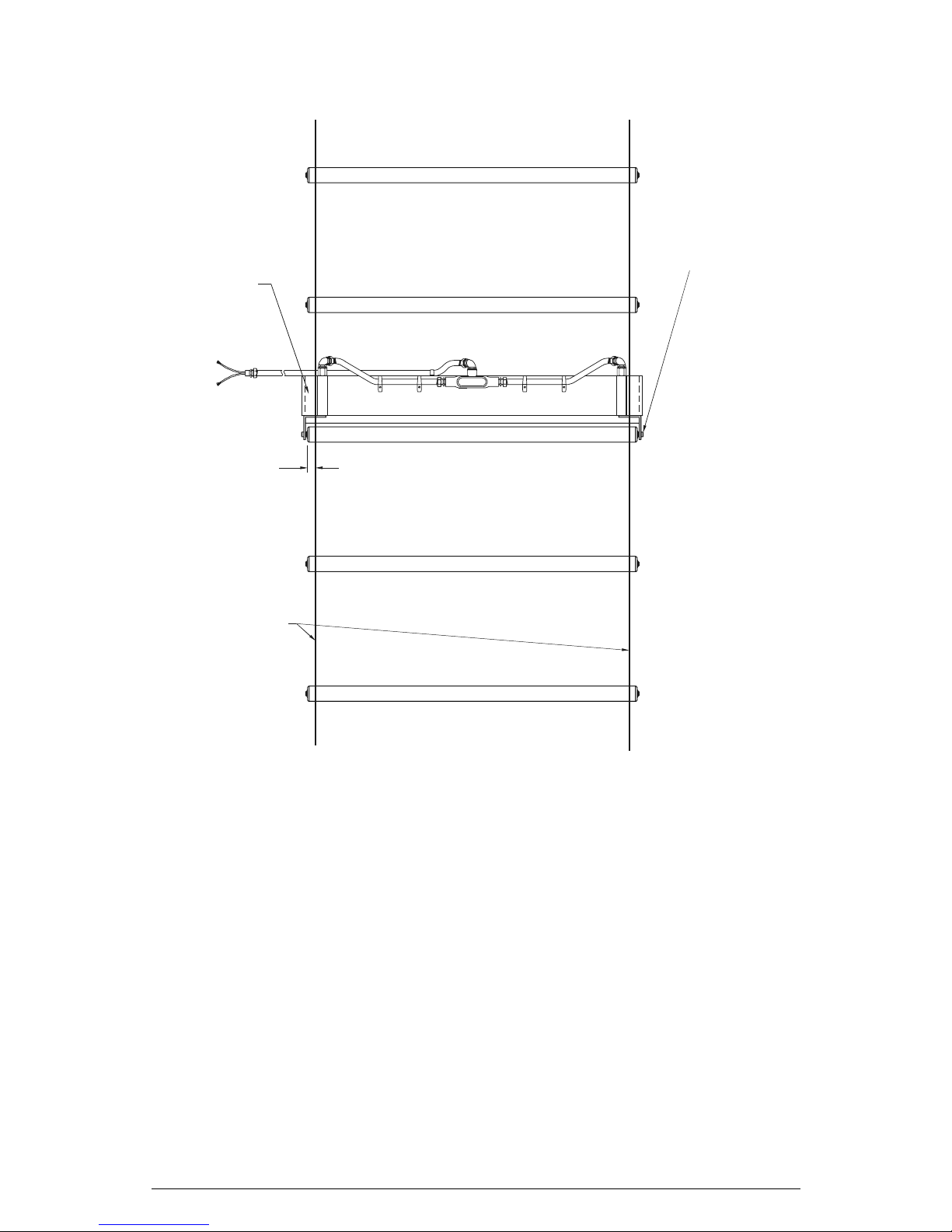
Plan View
low capacity
belt scale
this idler
supplied by
Siemens
Milltronics
25mm TYP. (1
(both sides)
aligning wire 0.5mm
dia. (0.020
equivalent
(customer supplied)
") or
")
7ML19985FF01 Milltronics MLC Belt Scale – INSTRUCTION MANUAL Page 7
Page 12
Calibration
General
After the MLC has been installed in accordance with the installation procedure,
calibration of the weighing system must be done in conjunction with the selected
integrator. Refer to the integrator instruction manual for programming and calibration.
The calibration is initially done using the calibrating test rod supplied with the scale.
Where possible, material tests are recommended to achieve maximum accuracy. (For
more information about material tests refer to the integrator manual.)
Test Load
The test load (stated in kilograms per meter or pounds per foot) for the MLC is stamped
on an aluminum tag fastened to the end of the calibrating test rod. Enter this value into
the integrator as the test load programming parameter.
If the actual idler spacing differs from the design data provided at time of purchase,
recalculate and re-enter a new test load value as follows:
test load (kg/m or lbs/ft) = Weight of calibrating rod (kg or lbs)
Actual idler spacing (m or ft)
Zero
Perform the zero calibration as described in the calibration section of the selected
integrator manual.
Span
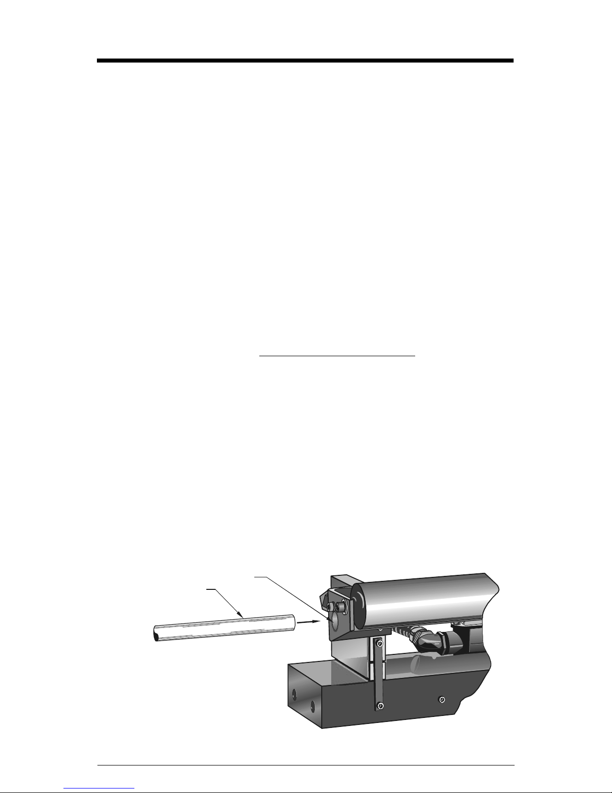
1. Insert the calibrating test rod into the 25mm (1") diameter retainer tube that is
mounted on the brackets that hold the idler to the load cells.
• It is located immediately below and to the side of the idler and is held in place by
flat washers retained by screws.
25mm (1
") retaining tube
test rod
Page 8 Milltronics MLC Belt Scale – INSTRUCTION MANUAL 7ML19985FF01
Page 13

• The tube is designed to move very slightly in its mounting to eliminate mutual
interference between the cells.
2. Slowly slide it all the way in until it contacts the end of the tube.
• Approximately 10 mm (3/8") of the rod should protrude from the tube.
3. Perform the span calibration as described in the calibration section of the selected
integrator instruction manual.
4. After the span calibration has been completed, remove the calibrating test rod and
store it in a convenient location.
Maintenance
Because the MLC has no moving parts, the scale requires no active maintenance. Once
the scale is installed into the conveyor, the conveyor becomes part of the total weighing
system. If a problem develops with the conveyor, that problem may also affect the scale.
For this reason, we recommend that a periodic conveyor maintenance program be
established for any conveyor that incorporates a scale.
REMINDER: Re-install the shipping stops during maintenance or any other time
when protection of the cells is necessary.
Spare Parts
The only spare part recommended for the MLC is the load cell. Refer to the load cell
nameplate for the proper size and then specify as follows when ordering.
For 10 pound cell: Milltronics Part Number PBD-23900155
For 20 pound cell: Milltronics Part Number PBD-23900156
Idler: Contact your Siemens Milltronics representative. Be prepared to provide
the serial number of the MLC unit.
7ML19985FF01 Milltronics MLC Belt Scale – INSTRUCTION MANUAL Page 9
Page 14
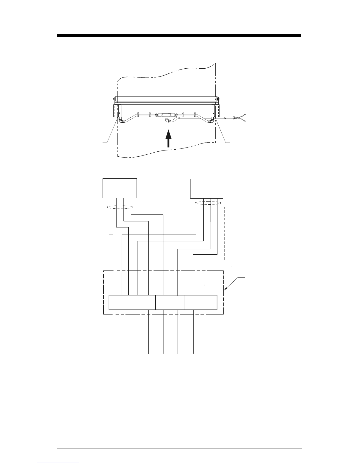
Wiring
load cell A
belt
travel
load cell B
load cell
A
r
r
e
e
d
d
‘B’
‘A’
+
e
x
c
load cell
B
b
b
w
g
w
g
s
l
l
h
r
h
k
k
t
n
‘B’
‘A’
‘A’
‘A’
-
e
x
c
+
s
s
i
i
g
g
‘A’
‘A’
r
t
n
‘B’
‘B’
+
s
s
i
i
g
g
‘B’
‘B’
s
h
h
l
l
d
d
‘A’
‘B’
s
h
i
e
l
d
customer
junction
box
Page 10 Milltronics MLC Belt Scale – INSTRUCTION MANUAL 7ML19985FF01
Page 15
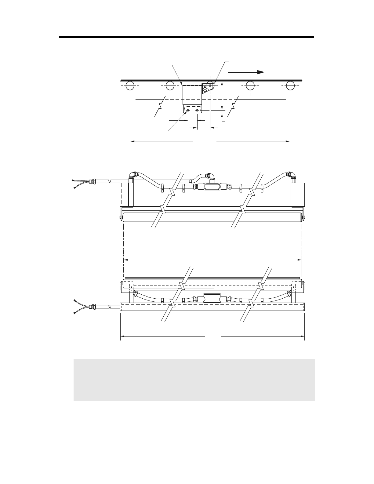
Dimensions
Installation
MLC Belt Scale
idler diameter C
location of removed idler
D
Plan View
Front View
64mm (2.5
4 x dia.
11mm (0.44
")
E
")
(see Note below)
*
A
20.6mm (0.812
")
Notes:
• For dimension values see next page.
* For pan supported belts, the pan should be cut out to allow the MLC and at least
two (preferably four) other idlers to be installed.
7ML19985FF01 Milltronics MLC Belt Scale – INSTRUCTION MANUAL Page 11
B
Page 16

Metric Designs (Europe)
Belt Width
450 mm
(17.72
")
500 mm
")
(19.69
650 mm
")
(25.59
800 mm
")
(31.50
1000 mm
")
(39.37
1200 mm
(47.24
")
A
DimensionB DimensionC DimensionD DimensionE Dimension
450 mm
(17.72")
500 mm
(19.69")
650 mm
(25.59")
800 mm
(31.50")
1000 mm
(39.37")
1200 mm
(47.24")
500 mm
(19.69")
550 mm
(21.65")
700 mm
(27.56")
850 mm
(33.46")
1050 mm
(41.34")
1250 mm
(49.21")
Imperial Designs (North America)
Belt Width
18" (457 mm) 18" (457 mm) 19" (483 mm) 1.90" (48.3 mm) 6.19" (157 mm) 3.5" (89 mm)
" (610 mm) 24" (610 mm) 25" (635 mm) 1.90" (48.3 mm) 6.19" (157 mm) 3.5" (89 mm)
24
30” (762 mm) 30
" (914 mm) 36" (914 mm) 37” (940 mm) 1.90" (48.3 mm) 6.19" (157 mm) 3.5" (89 mm)
36
" (1067 mm) 42" (1067 mm) 43" (1092 mm) 1.90" (48.3 mm) 6.19" (157 mm) 3.5" (89 mm)
42
" (1219 mm) 48" (1219 mm) 49" (1245 mm) 1.90" (48.3 mm) 6.19" (157 mm) 3.5" (89 mm)
48
A
DimensionB DimensionC DimensionD DimensionE Dimension
" (762 mm) 31" (787 mm) 1.90" (48.3 mm) 6.19" (157 mm) 3.5" (89 mm)
50 mm
(1.97")
50 mm
(1.97")
50 mm
(1.97")
50 mm
(1.97")
60 mm
(2.36")
60 mm
(2.36")
158 mm
(6.22")
158 mm
(6.22")
158 mm
(6.22")
158 mm
(6.22")
163 mm
(6.42")
163 mm
(6.42")
96 mm
(3.78")
96 mm
(3.78")
96 mm
(3.78")
96 mm
(3.78")
96 mm
(3.78")
96 mm
(3.78")
Page 12 Milltronics MLC Belt Scale – INSTRUCTION MANUAL 7ML19985FF01
Page 17

Index
A
animal feed pellets ...........................................1
approvals ............................................................2
B
belt speed ...........................................................2
belt width ............................................................2
C
calibrating test rod .....................................1, 8
calibration
capacity ..............................................................2
conveyor incline ...............................................2
F
fertilizer ...............................................................1
H
hazardous locations ........................................2
I
idler ......................................................................3
imperial designs ............................................ 12
installation ....................................................... 11
installation drawings
integrator ............................................................3
..........................................................8
alignment
diameter ....................................................2
profile ........................................................2
spacing
..................................................6
......................................................2
.......................................3
.....................................................................8
span
spare parts .........................................................9
specifications
static beam ........................................................1
strain gauges ....................................................3
...................................................................1
sugar
....................................................2
T
test load ..............................................................8
tobacco ...............................................................1
W
welding ...............................................................4
wiring ................................................................10
Z
zero calibration .................................................8
L
line .......................................................................6
load cell
loading ................................................................2
low-capacity operation
........................................................ 1, 2
...................................4
M
maintenance ................................................4, 9
metric designs
mounting
................................................ 12
.............................................................5
N
non-spec idler ...................................................3
O
OD tube ...............................................................1
P
precautions ........................................................4
products
..............................................................1
S
shipping stops .............................................4, 5
7ML19985FF01 Milltronics MLC Belt Scale – INSTRUCTION MANUAL Page 13
Page 18

Notes
Page 19

Page 20

www.siemens.com/processautomation
Siemens Milltronics Process Instruments Inc.
1954Technology Drive, P.O. Box 4225
Peterborough, ON, Canada K9J 7B1
Tel: (705) 745-2431 Fax: (705) 741-0466
Email: [email protected]
Siemens Milltronics Process Instruments Inc. 2008
Subject to change without prior notice
Rev. 1.2
*7ml19985FF01*
Printed in Canada
 Loading...