

Page 1

MicroMix 5
Shaker
User’s Manual
Document number: 600885-0001
Revision A
Date: March 2007
Copyright © 2006 by Siemens Medical Solutions Diagnostics. All rights reserved.
Page 2

Copyright © 2006 by Siemens Medical Solutions Diagnostics. All rights rese rved.
This manual, and the software described in this manual, are copyrighted. No part of this manual
or the described software may be copied, reproduced, translated or reduced to any electroni c
medium or machine-readable form without the prior written consent of Siemens Medical Solutions
Diagnostics except that you may make one copy of the program CD solely for back-up purposes.
IMMULITE® is a registered trademark of Siemens Medical Solutions Diagnostics.
All other products mentioned are trademarks of their respective companies.
Siemens Medical Solutions Diagnostics
Certificate No: UQA0113493
Siemens Diagnostics' quality products are manufactured under a quality
system that is registered to ISO 13485:2003.
Page 3

Table of Contents
Table of Contents 3
1. Introduction 4
2. Performance Characteristics and Specifications 6
Technical Specifications 6
Mechanical Specifications 6
Environmental Specifications 7
Controller 7
Power Supply 7
3. Installation 8
Unpacking 8
Requirements 9
Setting Up 10
4. Principles of Operation 13
5. Control Panel 14
Function Key [Function] 14
Digit Control Keys [Right], [Left] 15
Start/Stop Key [Start/Stop] 15
6. Operating Instructions 16
Recommended Default Settings 17
RS232 17
7. Operating Precautions and Limitations 18
General 18
Operation 18
Defects and Abnormal Stresses 18
8. Hazards 19
Environmental 19
Electrical 19
9. Service and Maintenance 20
Sensor Test 20
Alarm Test 20
EPROM Software Version Display 21
10. Appendix: Forms 22
11. Technical Assistance 25
MicroMix 5 ♦ 3
Page 4
1. Introduction
The MicroMix 5 (Catalog number: MMIX5) is a fully programmable
microplate and tube shaker. It allows complete control over the
amplitude, frequency, direction of rotation and duration of shaking. The
shaker has a capacity of four 96-well microplates, 120 tubes in one rack
(Rack 513) or up to two racks (Rack 500) of 96 tubes, and can also shake
tubes in foam racks.
This manual describes the installation, operation and maintenance of the
MicroMix 5. Before operating the MicroMix 5, read this manual in its
entirety, as it contains information necessary to ensure safe operation.
A set of preset shaking cycle patterns, called
memory. The user can select from a range of variables in the
Amplitude and Time display modes to create an optimal Mix mode
which suits a specific liquid viscosity and fill volume.
Not all tubes or wells in a microplate achieve resonance at the same
frequency. Unlike most shakers, the MicroMix 5 shakes through a range
of frequencies, ensuring that all tubes or wells in a microplate are mixed
uniformly.
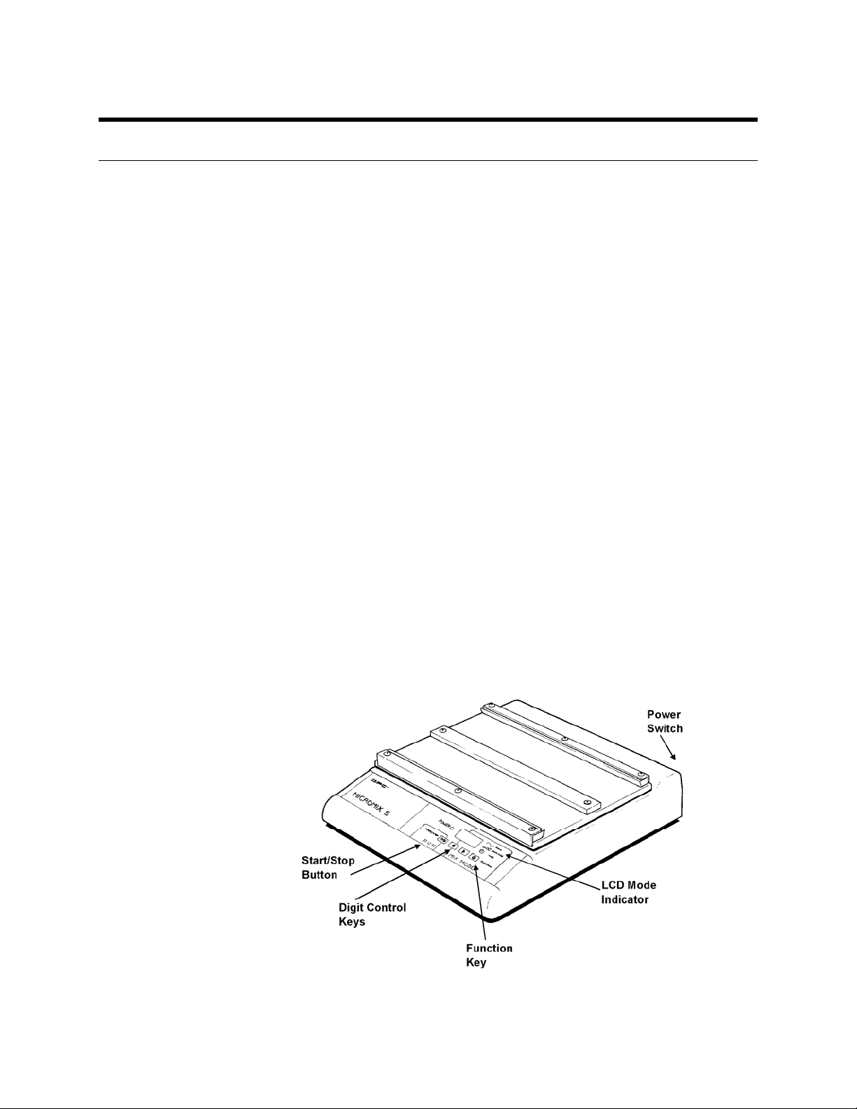
The MicroMix 5 consists of a base unit containing the control electronics,
the electromechanics, a panel-mounted keypad and a Liquid Crystal
Display (LCD). The base unit supports a lightweight but robust shaking
table with plate-retaining strips, which can be exchanged for a mat and
locators for shaking tubes.
The MicroMix 5 has a separate desktop power supply.
Forms, are stored in
Form,
4 ♦ MicroMix 5
Figure 1: MicroMix 5 Shaker
Page 5
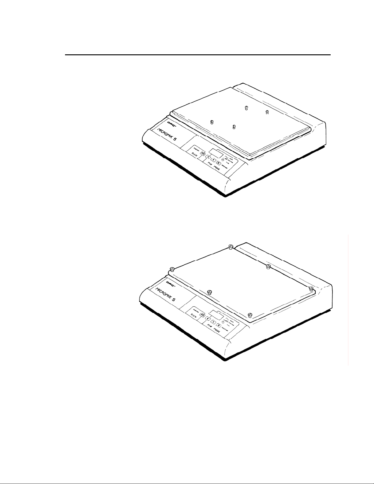
Introduction (cont.)
Tube Racks
(RACK 500, RACK 513)
Foam Racks for Tubes
Figure 2: MicroMix 5 in Tube Shaking Configurations
MicroMix 5 ♦ 5
Page 6

2. Performance Characteristics
and Specifications
Technical Specifications
The following are technical characteristics and specifications of the
MicroMix 5:
• Maximum power consumption: 50 VA
• Power voltage: 90 – 260 VAC, 47 Hz – 63 Hz
• Power inlet at rear panel of power supply module
• Maximum peak-to-peak shake amplitude: 2.5 mm
• Shaking mode: horizontal plane, circular
• Shaker orbital speed range (frequency): 300 – 1800 rpm (5 – 30 cycles
per second)
• Maximum capacity:
4 microplates
2 RACK 500 with 96 tubes per rack
1 RACK 513 with 120 tubes per rack
2 foam decanting racks with 100 tubes each
• Maximum shake mass:
2 kg evenly distributed on shaking table from 5 Hz – 20 Hz
0.5 kg evenly distributed on shaking table from 20 Hz – 30 Hz
Mechanical Specifications
The following are mechanical characteristics and specifications of the
MicroMix 5. The mechanical and electrical components are fixed to a
metal base plate. This is covered by a polyurethane foam case. The
microplates are supported on an aluminum table. Other characteristics
are:
• Footprint: 410 mm deep × 345 mm wide excluding power supply
6 ♦ MicroMix 5
• Height: 96 mm (overall height to seat of microplate)
• Weight: 6.7 kg; shipping weight: 8 kg
Vibration through the work surface is dampened by using feet made of
special isodamped material.
Page 7

Environmental Specifications
• Operating temperature: 0 to 40°C
• Storage temperature: –25 to 50°C
• Humidity: 10 to 90% RH, non-condensating
• RFC/EMI: Complies with EMC Directive 89/336/EEC
FCC 20780 Class B
VDE 0871 Level A
Controller
The controller comprises three main components:
1. Power inlet system, which consists of:
DC socket
Power switch
Interference suppression filter
Power Supply
2. Controller printed circuit board, incorporating front panel controls
and indicators
3. Drive electromagnets
This is a modular bench-top switched mode power supply and features:
• International Electrotechnical Commission (IEC) inlet
• Fusing
• Interference suppression
• DC output cable and plug
MicroMix 5 ♦ 7
Page 8
3. Installation
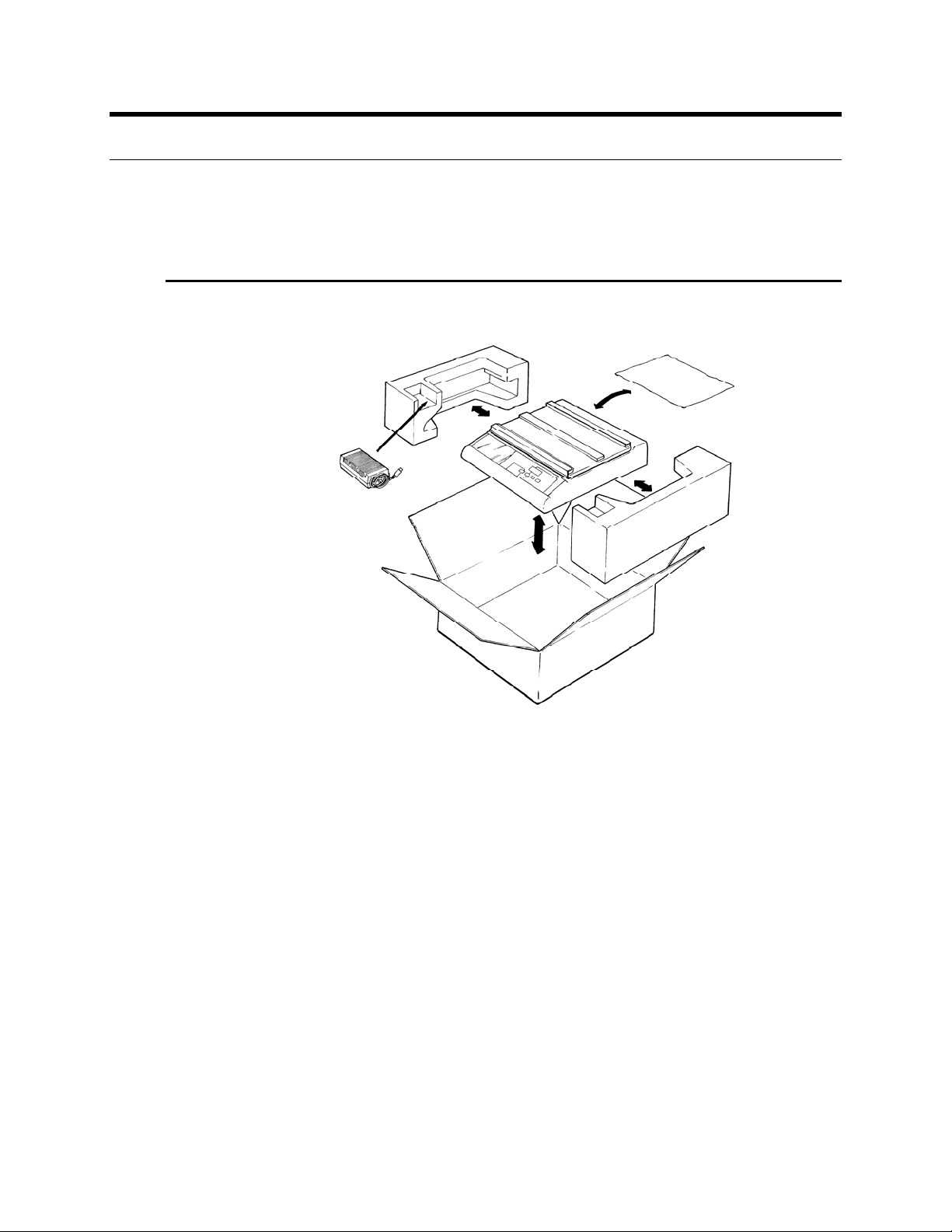
Unpacking
Follow Figure 3 for unpacking instructions.
Figure 3: Unpacking
The main box should consist of the following:
• MicroMix 5 Shaker
• Bench-top power supply
• Power cord, appropriate to your country
• Black foam mat (MAT 25)
• MicoMix 5 Shaker User's Manual
The accessories pack should consist of the following:
• Five rack pillars
• Seven shoulder screws and washers
• Small allen key screwdriver
8 ♦ MicroMix 5
Page 9

Requirements
Before plugging the external power supply into the Shaker and
connecting to an appropriate outlet, ensure that the following
requirements are met:
Site
The unit should be located on a level work surface free from strong
sources of electromagnetic interference, e.g. centrifuge motors.
The proper work surface should measure as follows:
Height: 20 cm (8 inches)
Depth: 45 cm (18 inches)
Width: 36 cm (14 inches)
Power Supply
Only the supplied power supply should be used. The power supply unit
accepts a supply voltage from 90 to 260 VAC and a frequency from 47 to
63 Hz. No adjustment is required.
CAUTION: This equipment requires connection to a properly grounded
power source for safety reasons.
MicroMix 5 ♦ 9
Page 10

Setting Up
The MicroMix 5 may be reconfigured to shake microtiter plates, or tubes
in racks or foams. The instrument is supplied preset to shake microtiter
plates.
10 ♦ MicroMix 5
Figure 4: Microtiter Plate Shaking
Items Required
1. One perspex center strip
2. Two side foam strips
3. Six large allen screws
4. Two small allen screws
5. Two plastic strips
6. Six spacers
7. One small allen key screwdriver
(Item 7 is in the accessory pack.)
Page 11

Setting Up (cont.)
Figure 5: Tubes, Foam Shaking
Items Required
1. Six shoulder screws
2. One black foam Mat. MAT 25 (250 × 334 mm, 10 × 12.5 inches)
3. One small hex key screwdriver
Ensure that when fitting screws they are not cross-threaded into the
shaker table top.
CAUTION: Do Not Overtighten the Screws
MicroMix 5 ♦ 11
Page 12

Setting Up (cont.)
Figure 6: Tubes, Rack Shaking
Items Required
1. One black foam Mat. MAT 25 (250 × 334 mm, 10 × 12.5 inches)
2. Four rack pillars
When rack pillars are unused, they may be stored at the rear of the
shaker. Caution must be exercised so as not to damage the threaded part
of the pillars.
Figure 7: Rack Pillar Storage Location
12 ♦ MicroMix 5
Page 13

4. Principles of Operation
Four diagonally arranged electromagnets fixed to the base are directed
towards four pole pieces fixed to the shaking table. The electromagnets
are activated and deactivated sequentially, so that the table shakes with
an orbital motion. The table is mounted on rubber mounts, which ensure
that the table moves only on a horizontal plane.
Motion is accurately controlled by a microcontroller. The amplitude is
detected using a proximity sensor, and is maintained, regardless of the
load, within the recommended operating range through dynamic
feedback techniques.
The low inertia of the table enables the frequency and direction of
mixing to be altered almost instantaneously. This also minimizes the
reaction to the shaker body and transmission of vibration to the work
surface.
The user may select one of a number of
Amplitude and Time (duration of shaking). A total of 60 Forms are
preset, with a subset of these optimized for plate shaking, tube shaking
and constant speed shaking. The default shaker settings
Amplitude and Time)
reprogrammed by the user.
selected when the shaker is switched ON may be
Forms and may also set the
(Form,
MicroMix 5 ♦ 13
Page 14

5. Control Panel
Figure 8: Control Panel
Legend
[Start/Stop] [Left]
[Function] [Right]
Function Key [Function]
The [Function] key is used to select any of three functions in which
preset values may be chosen by the operator. The function selected is
shown by the function indicator (appearing in the Mode Indicator
window) which moves sequentially between Form, Amplitude and
Time at each press of the key. The [Function] key also serves as a pause
control in RUN mode with a toggle action. Key depression is
acknowledged by a short audible "blip" unless the sounder is muted.
Form
The maximum number of Forms given with the MicroMix 5 is 60. Form
value 60 sets the instrument to TIMER mode only.
Form affects the following:
14 ♦ MicroMix 5
• Speed Shake direction
• Rest period between changing directions
See the Appendix for further details.
Page 15

Function Key (cont.)
Amplitude
The Amplitude selection ranges from 1 – 9, where 1 = minimum
amplitude, and 9 = maximum amplitude
Time
The timer has a range of 1 – 199 minutes. The value counts down to zero
from all nonzero values at the rate of 1 per minute after the [Start/Stop]
key has been depressed. Setting Time to "0" places the instrument in
continuous shaking mode. To stop continuous shaking, press the
[Start/Stop] key.
See the Appendix for further details.
Digit Control Keys [Right], [Left]
With the function indicator at the desired position, the Form, Amplitude
or Time number as indicated in the LCD may be adjusted by means of
the digit control keys as follows:
[Right] increases the value
[Left] decreases the value
A quick key depression changes the digit by one, while depressing the
key longer than 0.7 seconds causes an acceleration through the numerical
values. Digit wraparound is featured, i.e. each function returns to its
minimum value after passing its maximum value.
Start/Stop Key [Start/Stop]
Shaking and/or timing is started by depressing and releasing this key,
and may be stopped at any time by depressing the key again. As the time
counts down, the function indicator flashes every 2 seconds.
When Time = 0, the alarm sounds and shaking ceases.
When the shaker/timer or alarm is stopped by this key, the READY
mode is resumed with all the previously set parameters.
MicroMix 5 ♦ 15
Page 16

6. Operating Instructions
The power switch at the rear of the unit should be OFF (O) while
connecting the power supply to the shaker. The DC power supply input
may then be connected to the outlet.
1. Turn the power switch to ON (I). The controller produces two short
audible "blips"; the power ON indicator LED lights and the LCD
panel indicate a number with the function indicator on Form.
2. The recommended Form and Amplitude settings should be selected
and used for all assays, unless otherwise advised.
The Time setting should be adjusted according to assay instructions.
This is done by pressing the [Function] key to select Time, and using the
[Right], [Left] keys to select the appropriate value in minutes.
The default Time setting, 0, leaves the instrument in continuous shaking
mode.
3. Press the [Start/Stop] button to begin shaking.
4. Shaking action may be paused by pressing the [Function] key while
shaking is in action. The PAUSE mode is indicated by the function
indicator set at Time flashing at approximately three times per
second, and an audible warning consisting of 5 "ticks" per second.
In PAUSE mode, the timer is frozen and no power is applied to the
shaker table. Shaking and time countdown (where applicable) resumes
upon pressing the [Function] key a second time.
After switching the power OFF (O), a minimum interval of 5 seconds
should elapse before turning the power ON (I) again.
Sounder Mute
Switching the instrument ON while depressing the [Left] key mutes the
sounder until the instrument is switched OFF and switched ON
normally.
Resetting Power Up Setting
Switching the Instrument ON while depressing the [Left] and [Right]
keys will enable the default settings at power up to be changed. Using
the control panel, select the desired Form, Amplitude and Time.
Pressing the [Start/Stop] key will start the shaker with these parameters,
and permanently save them in internal memory (EPROM). The saving
mechanism is then disabled, and any other function selected will not be
saved.
16 ♦ MicroMix 5
When the instrument is subsequently switched ON it will default to the
new settings. To save a new set of default parameters, the procedure
must be repeated after switching on the instrument.
Page 17

Recommended Default Settings
The recommended parameters to obtain various modes of shaking for
assays are as indicated:
• For microtiter plate shaking, Form 20, Amplitude 5 may be used.
Other combinations may be considered as follows, Form 8, 22, 21, 17,
20 — all at Amplitude 5.
• For shaking tubes in TUBE DECANTING Foams with Siemens
Diagnostics assays use Form 25, Amplitude 7.
• For shaking tubes in RACK 500 or RACK 513 use Form 24,
Amplitude 7.
NOTE: The shaker will not be able to maintain full shake amplitude with
certain combinations of load, and selected Forms and Amplitude
settings above 7. Do not exceed the mass, as stated in the Technical
Specifications section.
RS232
There is an RS232 connector on the rear of the instrument to externally
control the shaker.
For further information please contact your Siemens Diagnostics
Distributor.
MicroMix 5 ♦ 17
Page 18

7. Operating Precautions and Limitations
General
Before operating the MicroMix 5, read this manual in its entirety, as it
contains information necessary to ensure safe operation.
Operation
Control samples and calibrators supplied with
should be processed by the MicroMix 5 in the same manner as test
samples. Strictly follow the instructions in the package inserts provided
by the manufacturer. Do not use magnets or magnetized items except
approved magnetic test tube racks near the equipment. Protection from
extremes of temperature and electrical interference is essential for proper
operation.
The instrument should be unpacked and installed in accordance with the
"Installation" section.
Ensure that the microplates are properly secured to the shaker platform
before operating the MicroMix 5.
Ensure that the racks are properly seated on the shaker platform pillars
before operating the MicroMix 5.
Ensure that foam decanting racks are properly affixed to the shaker
platform before operating the MicroMix 5.
Do not exceed the maximum volume of 300 µL per well in a standard 96well flat-bottom microplate.
in vitro diagnostic test kits
Defects and Abnormal Stresses
18 ♦ MicroMix 5
Whenever it is likely that the instrument's safe operation is
compromised, it should be made inoperative and secured against any
unintended operation.
The instrument's safety could be compromised, for example, if the
instrument:
• shows visible damage
• fails to perform the intended functions
• has been stored for a long time under unfavorable conditions
• has been subjected to severe transport stresses
Page 19

8. Hazards
Environmental
Infectious clinical samples and corrosive chemicals are commonly used
with this equipment. Although the shaker is designed to avoid spillage
under recommended working conditions, at higher amplitude settings
spillage may occur; hand and eye protection and laboratory coats
appropriate to the application should always be worn. If the shaker
platform comes into contact with spilled liquid, it should be cleaned
appropriately to avoid hazards.
Electrical
There are no USER SERVICEABLE PARTS within the MicroMix 5 and its
power supply.
Never substitute a different cable for the power cord supplied with the
instrument. The power cord should only be plugged into a power outlet
with a proper ground.
The precautions for using any electrical equipment apply to this device.
Do not use it during electrical storms. Do not touch switches or electrical
outlets with wet hands. Switch the instrument OFF (O) before
disconnecting.
MicroMix 5 ♦ 19
Page 20

9. Service and Maintenance
The MicroMix 5 is a highly reliable unit. This is achieved by the choice of
well-proven components, the small number of moving parts, the
minimal use of connectors and maximum use of digital techniques. The
microcontroller, driver system, associated electronics and front panel
controls and indicators are incorporated on a single printed circuit
board.
There are no USER SERVICEABLE PARTS within the MicroMix 5.
Authorized personnel only should carry out any necessary repairs to the
unit, as these may involve the use of specialized equipment and fixtures.
The following diagnostic modes may be terminated and regular
operation continued by depressing the [Start/Stop] key.
Sensor Test
Alarm Test
Perform the following Sensor Test at 6-month intervals:
1. Switch the instrument ON (I) while depressing the [Function] key.
This causes the LCD panel to indicate a value between 110 and 195
derived from the proximity sensor used for feedback control. The
value on the LCD panel should be noted.
2. Move the shaking platform by hand in the horizontal plane. This
causes the value to change on the LCD panel. When the shaking
platform is resting in its equilibrium state, the value indicated
should be between +/–10 of the previously indicated value. See
item 1.
3. If the displayed value is outside the stated limits, contact your
National Distributor for assistance.
For this optional test, switch the instrument ON while depressing the
[Right] key. This starts the alarm, which produces circular, sequential
patterns on the LCD with a repeated audible tone of four short "blips"
and one long “blip.”
20 ♦ MicroMix 5
Page 21

EPROM Software Version Display
Switch the instrument ON (I), while keeping the [Left] and [Function]
keys depressed. The EPROM software version is now displayed, e.g.
1.06. This is accompanied by a “chirping” sound. The mode may be
terminated by pressing the [Start/Stop] key. The instrument is now
ready for normal operation.
This feature is useful for checking the software version without having to
remove the instrument's cover or controller board.
MicroMix 5 ♦ 21
Page 22

10. Appendix: Forms
The following table illustrates the available Forms. The MicroMix 5
offers a total of 60 preset Forms. Further details are available upon
request from your distributor.
FORM
1 5 30 2 0.12 1.0
2 5 10 2 0.13 1.0
3 7.5 12.5 2 0.19 0.9
4 10 15 2 0.25 0.8
5 12.5 17.5 2 0.32 0.7
6 15 20 2 0.39 0.6
7 17.5 22.5 2 0.44 0.5
8 20 25 2 0.50 0.5
9 22.5 27.5 2 0.50 0.5
10 25 30 2 0.50 0.5
11 5 10 3 0.13 1.0
12 7.5 12.5 3 0.19 0.9
13 10 15 3 0.25 0.8
14 12.5 17.5 3 0.32 0.7
15 15 20 3 0.39 0.6
16 17.5 22.5 3 0.44 0.5
17 20 25 3 0.50 0.5
18 22.5 27.5 3 0.50 0.5
19 25 30 3 0.50 0.5
20 20 25 3 7.0 0.2
21 20 25 2 1.75 0.3
22 20 25 2 0.25 0.5
23 8 11.5 2 0.10 1.0
24 11 14.5 2 0.10 1.0
25 13 18 2 0.10 1.0
26 8 11.5 3 0.10 1.0
27 11 14.5 3 0.10 1.0
FRQ1
(Hz)
FRQ2
(Hz)
MODE
RAMP
(Hz/sec)
GAP
(sec)
22 ♦ MicroMix 5
Page 23

Appendix: Forms (cont.)
Fixed Speed Forms
Form
28 5 1 300
29 5 0 300
30 6.5 1 390
31 6.5 0 390
32 8.5 1 510
33 8.5 0 510
34 10 1 600
35 10 0 600
36 11.5 1 690
37 11.5 0 690
38 13.5 1 810
39 13.5 0 810
40 15 1 900
41 15 0 900
42 16.5 1 990
43 16.5 0 990
44 18.5 1 1110
45 18.5 0 1110
46 20 1 1200
47 20 0 1200
48 21.5 1 1290
49 21.5 0 1290
50 23.5 1 1410
51 23.5 0 1410
52 25 1 1500
53 25 0 1500
54 26.5 1 1590
55 26.5 0 1590
56 28.5 1 1710
57 28.5 0 1710
58 30 1 1800
59 30 0 1800
60 TIMER MODE
FRQ1/FRQ2
(Hz)
MODE
Speed
(RPM)
MicroMix 5 ♦ 23
Page 24

Appendix: Forms (cont.)
Form Parameter Definitions
FRQ1: Start Frequency (orbital speed)
FRQ2: End Frequency (FRQ2 ≥ FRQ1)
Defining FRQ1 and FRQ2 sets up a range of shaking frequencies in Hz
(cycles per second).
MODE
0 Constant direction, constant speed (clockwise).
1 Constant direction, constant speed (counter-clockwise).
2 Ramp frequency up, ramp frequency down, wait, change direction.
3 Ramp frequency up, wait, change direction, ramp frequency down,
wait, change direction.
RAMP: Frequency ramp rate (speed of change from one frequency to the
next through the range). Hertz per second.
GAP: Non-shaking period prior to change of direction. Seconds.
RPM: Speed of rotation for forms 0 and 1. Revolutions per minute.
Form 60
Selecting Form value 60 places the instrument in TIMER mode. No
shaking takes place in this mode. The instrument counts down from a set
time value, emitting an audible "tick" every second, while the function
indicator blinks.
The display shows the time remaining until the alarm sounds.
Starting and stopping the TIMER mode is detailed in the "Start/Stop
Key" section under "Control Panel."
Selecting Form 60 and setting the Time value to 0 activates the alarm
immediately.
If the sounder has been muted, no seconds will be heard "ticking" during
the TIMER mode, nor will there be an audible alarm when the time runs
out.
24 ♦ MicroMix 5
Page 25

11. Technical Assistance
For questions regarding the MicroMix 5 and its operation, or for service,
contact Technical Service at Siemens Diagnostics or your National
Distributor.
Tel: 973.927.2828
Fax: 973.927.0697
MicroMix 5 ♦ 25
 Loading...