

Page 1

MEMOSKOP 2/3/50/100/SUB
Service Instructions
SP
in connection with
SIREMOBIL 2000
© Siemens AG 1997
UROSKOP D1/D2
LITHOSTAR Multiline
English
Print No.: RX57-029.061.01.03.02 Doc. Gen. Date: 10.97
Replaces: RX57-029.061.01.02.02
The reproduction, transmission or
use of this document or its contents
is not permitted without express
written authority. Offenders will b e
liable for damages. All rights,
including rights created by patent
grant or registration of a utility
model _or_ design,_are_ reserved.
Page 2
0 - 2 Revision
Chapter Page Revision
0 1 to 4 03
1 1 to 4 02
2 1 to 2 02
3 1 to 2 02
4 1 to 2 03
5 1 to 2 02
6 1 to 6 03
7 1 to 4 02
8 1 to 2 02
MEMOSKOP 2/3/50/100/SUB RX57-029.061.01 Page 2 of 4 Siemens AG
Rev. 03 10.97 TD SD 24 Medical Engineering
Page 3

Contents 0 - 3
Page
1 _______Requirem ent s__________________ _____ ___________________ _________1-1
Documentation required. . . . . . . . . . . . . . . . . . . . . . . . . . . . . . . . . 1-1
MEMOSKOP . . . . . . . . . . . . . . . . . . . . . . . . . . . . . . . . . . . . . . 1-1
SIREMOBIL 2000 . . . . . . . . . . . . . . . . . . . . . . . . . . . . . . . . . . . . 1-1
LITHOSTAR Multiline . . . . . . . . . . . . . . . . . . . . . . . . . . . . . . . . . . 1-1
Uroskop D1/D2 . . . . . . . . . . . . . . . . . . . . . . . . . . . . . . . . . . . . . 1-1
Measur em ent instrum ents, auxiliar y d ev ic es and tools req uired . . . . . . . . . . . . 1-1
Protective conductor test . . . . . . . . . . . . . . . . . . . . . . . . . . . . . . . . 1-1
Removing the covers . . . . . . . . . . . . . . . . . . . . . . . . . . . . . . . . . . 1-2
SIREMOBIL 2000 . . . . . . . . . . . . . . . . . . . . . . . . . . . . . . . . . . 1-2
LITHOSTAR Multiline and URO SKOP D1/D2 . . . . . . . . . . . . . . . . . . . . 1-3
Attaching the covers. . . . . . . . . . . . . . . . . . . . . . . . . . . . . . . . . . . 1-3
2 _______Maintenance____________________________________________________2-1
Requirements . . . . . . . . . . . . . . . . . . . . . . . . . . . . . . . . . . . . . . 2-1
Visual inspection . . . . . . . . . . . . . . . . . . . . . . . . . . . . . . . . . . . . 2-1
Electrical safety . . . . . . . . . . . . . . . . . . . . . . . . . . . . . . . . . . . . . 2-1
Cleaning. . . . . . . . . . . . . . . . . . . . . . . . . . . . . . . . . . . . . . . . . 2-1
Functional inspection . . . . . . . . . . . . . . . . . . . . . . . . . . . . . . . . . . 2-1
Final steps. . . . . . . . . . . . . . . . . . . . . . . . . . . . . . . . . . . . . . . . 2-1
3 _______Loading the software ____________________________________________3-1
Perform download. . . . . . . . . . . . . . . . . . . . . . . . . . . . . . . . . . . . 3-1
with SIREMOBIL 2000 . . . . . . . . . . . . . . . . . . . . . . . . . . . . . . . . . 3-1
with LITHOSTAR MULTILINE . . . . . . . . . . . . . . . . . . . . . . . . . . . . . . 3-1
with UROSKOP D1/D2 . . . . . . . . . . . . . . . . . . . . . . . . . . . . . . . . . 3-1
4 _______Calling up the service menu_______________________________________4-1
SIREMOBIL 2000 . . . . . . . . . . . . . . . . . . . . . . . . . . . . . . . . . . . . 4-1
Calling up the memory and TV test images . . . . . . . . . . . . . . . . . . . . . . . 4-1
Memory test images on SIREMOBIL 2000 . . . . . . . . . . . . . . . . . . . . . 4-1
LITHOSTAR Multiline . . . . . . . . . . . . . . . . . . . . . . . . . . . . . . . . . . 4-1
UROSKOP D1/D2. . . . . . . . . . . . . . . . . . . . . . . . . . . . . . . . . . . . 4-2
Activate set-up mode . . . . . . . . . . . . . . . . . . . . . . . . . . . . . . . . 4-2
Exit set-up mode. . . . . . . . . . . . . . . . . . . . . . . . . . . . . . . . . . . 4-2
5 _______Electrical settings/programming ___________________________________5-1
SIREMOBIL 2000 . . . . . . . . . . . . . . . . . . . . . . . . . . . . . . . . . . . . 5-1
UROSKOP D1/D2. . . . . . . . . . . . . . . . . . . . . . . . . . . . . . . . . . . . 5-1
Activate set-up mode . . . . . . . . . . . . . . . . . . . . . . . . . . . . . . . . 5-1
Exit set-up mode. . . . . . . . . . . . . . . . . . . . . . . . . . . . . . . . . . . 5-1
LITHOSTAR Multiline . . . . . . . . . . . . . . . . . . . . . . . . . . . . . . . . . . 5-2
Siemens AG RX57-029.061.01 Page 3 of 4MEMOSKOP 2/3/50/100 /SUB
Medical Engineer ing Rev . 03 10.97 TD SD 24
Page 4

0 - 4 C ontents
Page
6 ______ PC board replacement____________________________________________6-1
For MEMOSKOP 3 / 50 / (100) / SUB 2000 . . . . . . . . . . . . . . . . . . . . . . . 6-1
Opening the MEMOSKOP . . . . . . . . . . . . . . . . . . . . . . . . . . . . . . 6-1
Closing the MEMOSKOP. . . . . . . . . . . . . . . . . . . . . . . . . . . . . . . 6-1
Replacing memory board D1 . . . . . . . . . . . . . . . . . . . . . . . . . . . . . 6-1
Additional work, depending on the specific system: . . . . . . . . . . . . . . . . . 6-1
For MEMOSKOP 50 . . . . . . . . . . . . . . . . . . . . . . . . . . . . . . . . . . . 6-2
Replacing board D2 (memory with SCSI) . . . . . . . . . . . . . . . . . . . . . . 6-2
Additional work, depending on the specific system. . . . . . . . . . . . . . . . . . 6-2
For MEMOSKOP 3 . . . . . . . . . . . . . . . . . . . . . . . . . . . . . . . . . . . . 6-2
Replacing board D21 (memory without SCSI) . . . . . . . . . . . . . . . . . . . . 6-2
For MEMOSKOP SUB 2000 . . . . . . . . . . . . . . . . . . . . . . . . . . . . . . . 6-3
Replacing board D22 . . . . . . . . . . . . . . . . . . . . . . . . . . . . . . . . . 6-3
Additional work . . . . . . . . . . . . . . . . . . . . . . . . . . . . . . . . . . . . 6-3
Replacing board D23 . . . . . . . . . . . . . . . . . . . . . . . . . . . . . . . . . 6-3
MEMOSKOP 50 and MEMOSKOP SUB 2000. . . . . . . . . . . . . . . . . . . . . . 6-4
Replacing the longitudinal control D3 (12 V, Fig. 1) . . . . . . . . . . . . . . . . . 6-4
Replace m ent of switchin g c ontrol D4 (5 V, F ig. 2) . . . . . . . . . . . . . . . . . . 6-4
Replacement of disk drive MS1. . . . . . . . . . . . . . . . . . . . . . . . . . . . 6-5
For MEMOSKOP 2/2K . . . . . . . . . . . . . . . . . . . . . . . . . . . . . . . . . . 6-6
Replacing memory board D17 . . . . . . . . . . . . . . . . . . . . . . . . . . . . 6-6
Replacing interface board D18 . . . . . . . . . . . . . . . . . . . . . . . . . . . . 6-6
7 ______ Laser camera timing (not for MEMOSKOP 2) _________________________7-1
Timing diagram . . . . . . . . . . . . . . . . . . . . . . . . . . . . . . . . . . . . . . 7-1
Changing the times. . . . . . . . . . . . . . . . . . . . . . . . . . . . . . . . . . . . 7-1
Prerequisites . . . . . . . . . . . . . . . . . . . . . . . . . . . . . . . . . . . . . 7-1
Opening Setup . . . . . . . . . . . . . . . . . . . . . . . . . . . . . . . . . . . . 7-1
Changing the precontact time TV. . . . . . . . . . . . . . . . . . . . . . . . . . . 7-1
Changing the contact time TK . . . . . . . . . . . . . . . . . . . . . . . . . . . . 7-2
Changing the postcontact time TN . . . . . . . . . . . . . . . . . . . . . . . . . . 7-2
Exit Setup. . . . . . . . . . . . . . . . . . . . . . . . . . . . . . . . . . . . . . . 7-2
Video timin g . . . . . . . . . . . . . . . . . . . . . . . . . . . . . . . . . . . . . . . 7-3
8 ______ Changes as compared to previous versions _________________________8-1
MEMOSKOP 2/3/50/100/SUB RX57-029.061.01 Page 4 of 4 Siemens AG
Rev. 03 10.97 TD SD 24 Medical Engineering
Page 5

Requirements 1
Safety notes
Always switch the system off when performing work on the Memoskop.
Documentation required 1
This document RX57-029.061.01..applies to SIREMOBIL 2000, LITHOSTAR Multiline
and UROSKOP D1/D2.
MEMOSKOP 1
• MEMOSKOP 2 X2146
• MEMOSK OP 3/50/( 100) and SU B 2000 X2009
SIREMOBIL 2000 1
• Service instructions RR2-120.061.02..
LITHOSTAR Multiline 1
1 - 1
• Setting the software para meters RXL2-120.03 2.02..
• Service software contr ol RXL2-120.113.01..
Uroskop D1/D2 1
• Handling service software RLL5-310.113.02..
• Calling up the set-up mode (see page 5-1)
Measurem en t instrument s, auxiliary de vic es an d to ols required 1
• Digital multimeter Fluke 8060A 97 02 101 Y4290
• Service PC
• Service tool kit
• MEMOSKOP keyboard 11 02 669 X2009
• Protective conductor meter 44 15 899 RV090
• Serial PC connect ion cable for service PC 99 00 440 RE 999
Protective conductor test 1
After finish ing all work ste ps and attaching all covers, pe rf orm the protec t iv e c onductor
test according to ARTD-002.731.16.
The protective conductor resistance must not exceed 0.2 O.
• When working on parts connected to line voltage, there is the risk of electric shock.
• To comply with EMC regulations, PC board shielding must be installed properly.
• Always switch the system off or disconnect the power plug prior to removing the covers.
Siemens AG RX57-029.061.01 Page 1 of 4 MEMOSKOP 2/3/50/100/SUB
Medical Engineer ing Rev . 02 10.97 TD SD 34
Page 6
1 - 2 Requirements
Removing th e cov er s 1
SIREMOBIL 2000 1
3
1
2
Fig. 1
Basic unit back cover
• Lock the f oot bra ke.
• Switch off the system and disconnect it from the line voltage.
• Using the Allen key, remove the three screws in the rubber strip (1/Fig. 1).
• Hold the cover at the bottom and pull it back.
• Hold the cover at the bottom and pull it downward.
• Holding the cover at the top, pull up and to the back to remove it.
• Remove the protective conductor and retighten the protective conductor screw slightly.
Basic unit side cover
• First remove the re ar cover.
• Remove the screws from the rubber strip (2/Fig.1).
• Loosen the screws on the top (3/Fig.1).
• Remove the cover toward the s ide.
• Remove the protective co nductor and reti ghten the scr ew slightly.
Rear cover of the SM2000 monitor trolley
• Remove the cover screws.
• Remove the protective co nductor.
MEMOSKOP 2/3/50/100/SUB RX57-029.061.01 Page 2 of 4 Siemens AG
Rev. 02 10.97 TD SD 34 Medical Engineering
Page 7

Requirements 1 - 3
LITHOSTAR Multiline and UROSKOP D1/D2 1
• Switch the system off and disconnect it from the line voltage.
• After removing the scr ews, detach t he front cover o f the uni t cabinet.
• Remove the protective co nductor.
Attaching the covers 1
• After all service work is complete, reattach the covers as described under "Removing
the covers" , but proceed in the reverse order.
• Realign the contact springs of the basic unit covers with the edges of the cover panels
( SIREMOBIL 2000 only).
• Ensure that the protective conductors are properly connected.
Siemens AG RX57-029.061.01 Page 3 of 4 MEMOSKOP 2/3/50/100/SUB
Medical Engineer ing Rev . 02 10.97 TD SD 34
Page 8

1 - 4 Requirements
This page int entionally left blank.
MEMOSKOP 2/3/50/100/SUB RX57-029.061.01 Page 4 of 4 Siemens AG
Rev. 02 10.97 TD SD 34 Medical Engineering
Page 9

CAUTION
Maintenance 2
Requirements 2
The requirements des c ribed in Chapt er 1 of these instructions apply to mainte nance as
well.
Visual inspe ct io n 2
• Check the whole system for damage and secure mo untings.
Electrical safety 2
• Check that warning labels are complete and in good condition. Replace them, if
necessary.
• Check cables and connectors for damage. Replace them, if necessary.
The protective conductor test is part of the safety inspection and
should be performed when maintenance work is complete and the
system is closed. Refer to "Final steps".
2 - 1
Cleaning 2
• Clean the fan.
• Remove any dust or dirt.
Functi on al ins pectio n 2
• Perform a functional check and image quality test in accordance with the associated
documentation (diagnostic test, IQ binder).
Final steps 2
• With the system/unit cl osed, perform a protective co nductor test.
Siemens AG RX57-029.061.01 Page 1 of 2 MEMOSKOP 2/3/50/100/SUB
Medical Engineer ing Rev . 02 10.97 TD SD 34
Page 10

2 - 2 Maintenance
This page int entionally left blank.
MEMOSKOP 2/3/50/100/SUB RX57-029.061.01 Page 2 of 2 Siemens AG
Rev. 02 10.97 TD SD 34 Medical Engineering
Page 11

Loading the software 3
Perform download 3
with SIREMOBIL 2000 3
• Refer to chapter 4 of the Service instructions, RR2-120.061.02.
with LITHOSTAR MULTILINE 3
• Refer to chapter 3 in Operating Service software , RXL2-120.113.01.
with UROSKOP D1/D2 3
• Refer to chapter 11 in Operating Service software, RLL5-310.113.02.
3 - 1
Siemens AG RX57-029.061.01 Page 1 of 2 MEMOSKOP 2/3/50/100/SUB
Medical Engineer ing Rev . 02 10.97 TD SD 34
Page 12

3 - 2 Loading the software
This page int entionally left blank.
MEMOSKOP 2/3/50/100/SUB RX57-029.061.01 Page 2 of 2 Siemens AG
Rev. 02 10.97 TD SD 34 Medical Engineering
Page 13

Calling up the service menu 4
4 - 1
Fig. 1
5
4
2
3
SIREMOBIL 2000 4
• Switch the system "ON"
Calling up the memory and TV test images 4
• Press and hold the following buttons on the SIREMOBIL control console in the
sequence shown:
1. ATB (manual image release) button on the hand switch,
2. Button (2/Fig.1) on the control console,
3. and multiformat camera release button (3/Fig.1)
The "internal service menu" is displayed on the control console (Fig.1).
• After approx. 1 second, release all the buttons.
Memory test images on SIREMOBIL 2000 4
• Press the third button (soft key, 4/Fig. 1) on the control console and wait until a memory
test image is reconstructed ( approx. 15 seco nds).
• Page through the memory test images by pressing the third soft key (4/Fig.1).
• You can exit the service menu by pressing the same key combination as for calling up
the service menu.
LITHOSTAR Multiline 4
• Call up the LITHOSTAR Multiline service menu.
Refer to "Setting the software parameters" RXL2-120.032. 02...
Siemens AG RX57-029.061.01 Page 1 of 2 MEMOSKOP 2/3/50/100/SUB
Medical Engineer ing Rev. 03 10.97 TD SD 34
Page 14

4 - 2 Calling up the service menu
NOTICE
UROSKOP D1/D2 4
• Switch the system "ON"
• Wait fo r th e MEM OSKOP to b oot.
Activate set-up mode 4
<x> means: press key x.
<CTRL> + <E> means: press and hold <CTRL> and simultaneously press key <E>.
• Press the following keys on the keyboard in sequence:
- <NEXT PAT>
-<@>
-<%>
- <CTRL> + <S >
After activating set-up mode, a sequence of numbers is displayed in the lower image
region of the monitor.
• To call up the test images, overwrite this sequence of numbers.
• Enter the number sequence with out any blanks.
Depending on the test image, re construction may t ake up to 3 0 seconds.
Test images:
- SMPTE-similar test image 0000 8808 0A0303C F00
- Gray wedg e hori zont al 0000 8 808 0 A030 21 C00
- Black/white step 0000 8808 0A03023 C 00
- Gray scale 0%-100%(linear) 0000 8808 0A03025 C00
- Gray scale 0%-100% (exponential) 0000 8808 0A03026 C00
- Black 0% 0000 8808 0A03027 C00
- Vertical white bar 60% 0000 8808 0A03028 C00
• Press keys <CTRL> + <E >.
Exit set-up mode 4
• Switch the system "OFF" and back "ON" again.
The memory returns to normal operating mode.
MEMOSKOP 2/3/50/100/SUB RX57-029.061.01 Page 2 of 2 Siemens AG
Rev. 03 10.97 TD SD 34 Medical Engineering
Page 15

Electrical settings/programming 5
CAUTION
NOTE
SIREMOBIL 2000 5
• For the configuration of the MEMOSKOP 3/50/(100)
refer to chapter 5 of the service instructions RR2-120.061.02.. .
• For the configuration of the MEMOSKOP SUB 2000
refer to chapter 5 of the service instructions RR2-120.061.02.. .
UROSKOP D1/D2 5
• For the configuration of the Memoskop 50 / (100)
If PC board D18 on MEMOSKOP 2K or PC board D1 or D2 on
MEMOSKOP 50/(100) is replaced, a download of the MEMOSKOP
software must be performed on UROSKOP.
If PC board D1 is being replaced in MEMOSKOP 50/(100), the
MEMOSKOP must be configured additionally via the keyboard.
• Switch the system "ON"
• Wait for the MEMOSKOP to boot.
5 - 1
Activate set-up mode 5
<x> mean s: press key x.
<CTRL> + <E> means: press and hold <CTRL> and simulta-
neously press key <E>.
• Actuate the following keys on the keyboard in sequence:
- <NEXT PAT>
-<@>
-<%>
- <CTRL> + <S >
• After activating set-up mode, a sequence of numbers is displayed in the lower region of
the monitor image.
• Enter the values indica ted for the r elevant TV syste m on the keybo ard:
- for TV systems with 60Hz and 120 Hz memory output:
02 00 66 08 FE FF FF 01 02 32 63 63
- for TV systems with 50 Hz and 10 0 Hz memory output:
02 00 66 08 FF FF FF 01 02 32 63 63
• Enter the numbers without any blanks.
• Press the keys <CTRL> + <E>.
Exit set-up mode 5
• Switch the system "OFF" and "ON" again.
The memory returns to normal operating mode.
Siemens AG RX57-029.061.01 Page 1 of 2 MEMOSKOP 2/3/50/100/SUB
Medical Engineer ing Rev. 02 10.97 TD SD 34
Page 16

5 - 2 Electrical settings/programming
LITHOSTAR Multiline 5
• For the configuration of Memoskop 3 / (100)
refer to "Setting the software parameters" RXL2-120.032.02...
MEMOSKOP 2/3/50/100/SUB RX57-029.061.01 Page 2 of 2 Siemens AG
Rev. 02 10.97 TD SD 34 Medical Engineering
Page 17

PC board replacement 6
CAUTION
For MEMOSKOP 3 / 50 / (100) / SUB 2000 6
Opening the MEMOSKOP 6
Observe ESD regulations.
• Open the EMC cover over the plugboard on board D1.
• Remove the plugs.
• Remove all the screws of the EMC cover.
• Remove the self-adhesive copper foil within the plugboard from the EMC cover.
• Remove the power plug.
• Detach the EMC cover.
Closing the MEMOSKOP 6
• Place the EMC cover on the MEMOSKOP.
• Reinsert and connect all plugs.
6 - 1
• Reattach the EMC cover wit h the screws.
• Reattach the self-adhesive copper foil to the EMC cover.
• Close the EMC cover.
Ensure that the cable shielding makes proper contact with the contact strip of the EMC
cover.
Replacing memory board D1 6
• Remove the screws on the two tilt levers of board D1.
• Press board D1 with the two tilt levers upwards and remove it.
• Insert the new board.
• Tilt down the lever and reinsert the screws.
• Reconnect the plug.
Additional work, depending on the specific system: 6
• Update the customer data in the bottom line.
Procedure:
- Actuate the text entry button and move the cursor to the "hospital line" (lowest line)
using the arrow keys.
- Update the customer data.
- After entering all the customer data, move the cursor out of the hospital line using the
arrow key.
• Switch off the syst em.
The customer data is now stored automatically in the Memoskop.
• For SIREMOBIL 2000:
- Perform Download according to chapter 6 of the instructions RR2-120.061.02.. .
- Perform Configuration according to chapter 5 of the instructions RR2-120.061.02...
Siemens AG RX57-029.061.01 Page 1 of 6 MEMOSKOP 2/3/50/100/SUB
Medical Engineer ing Rev. 03 10.97 TD SD 34
Page 18

6 - 2 PC board replacement
• For LITHOSTAR Multiline
- Perform Download according to the instructions RXL2-120.113.01...
- Perform Configuration according to the instructions RXL2-120.032.02...
• For UROSKOP D1/D2
- Perform Download according to the instructions RLL5-310.113.02...
- Perform Configuration according to page 5-1 of these instructions.
For MEM OS KO P 50 6
Replacing board D2 (memory with SCSI) 6
• Remove the attachment scre ws on the two tilt levers of the D2 board.
• Remove board D2.
• When removing board D2, be careful not to damage the flat ribbon cable.
• Tilt the lever down on the flat ribbon cable plug and remove the plug.
• Connect the plug to the new board.
• Insert the new D2 board and reattach the tilt levers.
Additional work, depending on the specific system 6
• On SIREMOBIL 2000
Perform Download according to the instructions RR2-120.061.02...
• On LITHOSTAR Multiline
Perform Download according to the instructions RXL2-120.113.01...
• On UROSKOP D1/D2
Perform Download according to the instructions RLL5-310.113.02...
For MEM OS K OP 3 6
Replacing board D21 (memory without SCSI) 6
• Open the MEMOSKOP.
• Remove the screws on the t wo tilt le vers of the D21.
• Remove board D21, insert the new board and reattach the tilt levers.
• No service work is necessary.
• Close the MEMOSKOP.
MEMOSKOP 2/3/50/100/SUB RX57-029.061.01 Page 2 of 6 Siemens AG
Rev. 03 10.97 TD SD 34 Medical Engineering
Page 19

PC board replacement 6 - 3
For MEMOSKOP SUB 2000 6
Replacing board D22 6
• Open the MEMOSKOP.
• Remove the screws on the two tilt levers of the D22.
• Remove board D22; be careful not to damage the flat ribbon cable.
• Tilt the lever down on the plug of the flat ribbon cable and remove the plug.
• Remove board D23 from the old D22 and insert in the new D22.
• Reinsert the new D22 and reconnect the flat ribbon cable.
• Reattach the screws of the two tilt levers.
Additional work 6
• On SIREMOBIL 2000
Perform Download according to the instructions RR2-120.061.02...
Replacing board D23 6
• Remove board D22 as described under ”Replacing board D22,
MEMOSK OP SUB 100” .
• Remove board D23 from board D22.
• Remove all plug connections.
• Attach the new D23 board.
• Reinstall all plug connections.
• Reinsert D22 without damaging the flat ribbon cable.
• Close the MEMOSKOP.
Siemens AG RX57-029.061.01 Page 3 of 6 MEMOSKOP 2/3/50/100/SUB
Medical Engineer ing Rev. 03 10.97 TD SD 34
Page 20

6 - 4 PC board replacement
Longitudinal control D3 (detail)
+12V
GREE
+12V
settin
D
V
R
D
V
+5V
GREE
R
+5V
settin
Switching control D4 (detail)
Fig. 1 Fig. 2
MEMOSKOP 50 and MEMOSKOP SUB 2000 6
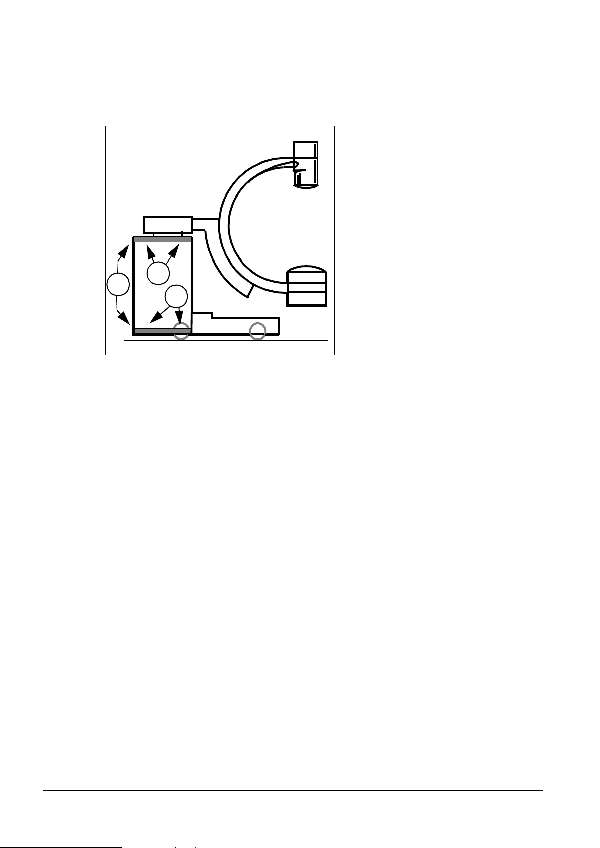
Replacing the longitudinal control D3 (12 V, Fig. 1) 6
• Open the MEMOSKOP.
• Remove the large cover f rom MEMOSKOP.
• Remove longitudinal control D3.
• Insert the new longitudinal control.
• No additional adjustments are necessary.
• Reattach the cover with the screws.
• Close the MEMOSKOP.
Replacement of switching control D4 (5 V, Fig. 2) 6
• Open the MEMOSKOP.
• Remove the large cover from the MEMOSKOP.
• Remove switching control D4.
• Insert the new switching control.
• Reattach the cover with the screws.
• Close the MEMOSKOP.
• No additional adjustments are necessary.
MEMOSKOP 2/3/50/100/SUB RX57-029.061.01 Page 4 of 6 Siemens AG
Rev. 03 10.97 TD SD 34 Medical Engineering
Page 21

PC board replacement 6 - 5
CAUTION
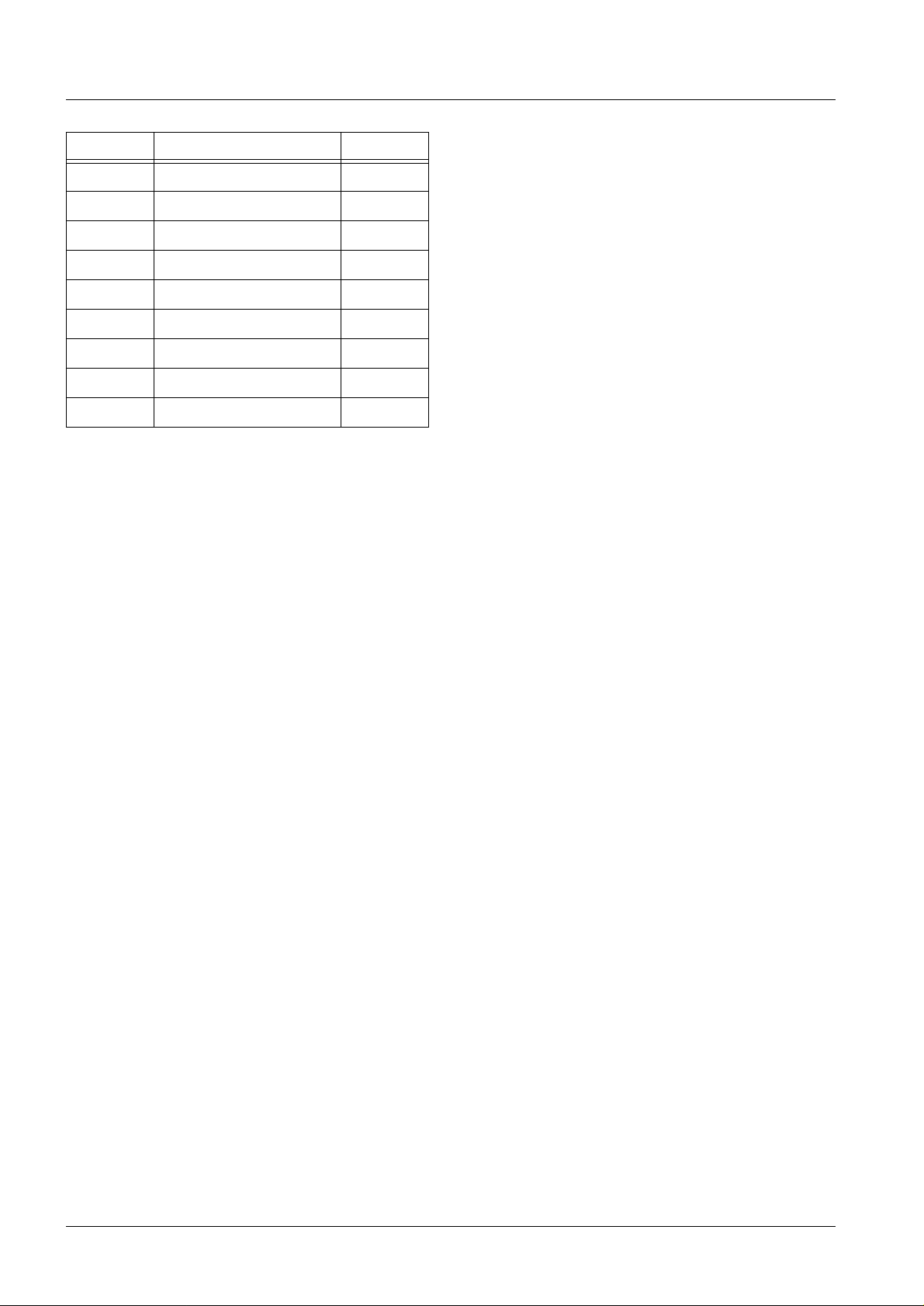
Replacement of disk drive MS1 6
• Open the MEMOSKOP.
• Remove the large cover from MEMOSKOP.
• Remove the disk drive.
• Disconnect the plug.
• Remove the metal holder from the drive.
Do not lose the spacers. They are required when installing the
disk drive to provide insulation.
• Insert jumpers according to the table .
• Attach the metal holder including spacers to the new drive.
• Connect the plug to the new drive.
• Insert the new drive in the location of the old one.
The drive must not contact any of the other components.
• Reattach the cover.
• Close the MEMOSKOP .
Quantum
LPS, ELS, F B
-A0 open J4 Jumper
A1 jumpered J4 Jumper
A2 jumpered J4 Jumper
*1)
SS
EP
WS
TE
PK
*1)
*1)
*1)
*1)
open J1 Jumper
open J1 Jumper
open J2 Jumper
jumpered
open
Seagate
ST 31 250 N
7-8
9-10
1 1-12
1-2
5-6
5-6
Labeling
*3)
open J8 Jumper
jumpered J8 Jumper
jumpered J8 Jumper
jumpered J8 Jumper
23-24
jumpered J8 Jumper
28-30
jumpered J8 Jumper
32-34
Seagate
ST 51 080 N
5-6
3-4
1-2
*2)
*2)
*3
open
jumpered
jumpered
jumpered
jumpered
jumpered
All other ex is t ing jumpers rem ain open
*1)
*2)
*3)
Siemens AG RX57-029.061.01 Page 5 of 6 MEMOSKOP 2/3/50/100/SUB
Medical Engineer ing Rev. 03 10.97 TD SD 34
If applicable
Substitut e jumper, if applicable
Software VA07A must be loaded in the M EMOSKOP.
Page 22

6 - 6 PC board replacement
CAUTION
For MEM OS KO P 2/ 2 K 6
Repla cing me mory board D17 6
Observe ESD regulations
.
• On SIREMOBI L 2000
Replace board D17 according to chapter 6 of the instructions RR2-120.061.02.
• On UROSKOP D1
- Replace board D17.
- No additional service work is necessary.
Replacing interface board D18 6
• On SIREMOBIL 2000
Replace board D18 according to chapter 6 of the instructions RR2-120.061.02.
• On UROSKOP D1
- Replace board D18.
- Perform Download according to the instructions RLL5-310.113.02.
MEMOSKOP 2/3/50/100/SUB RX57-029.061.01 Page 6 of 6 Siemens AG
Rev. 03 10.97 TD SD 34 Medical Engineering
Page 23
Laser camera timing (not for MEMOSKOP 2) 7
Notice
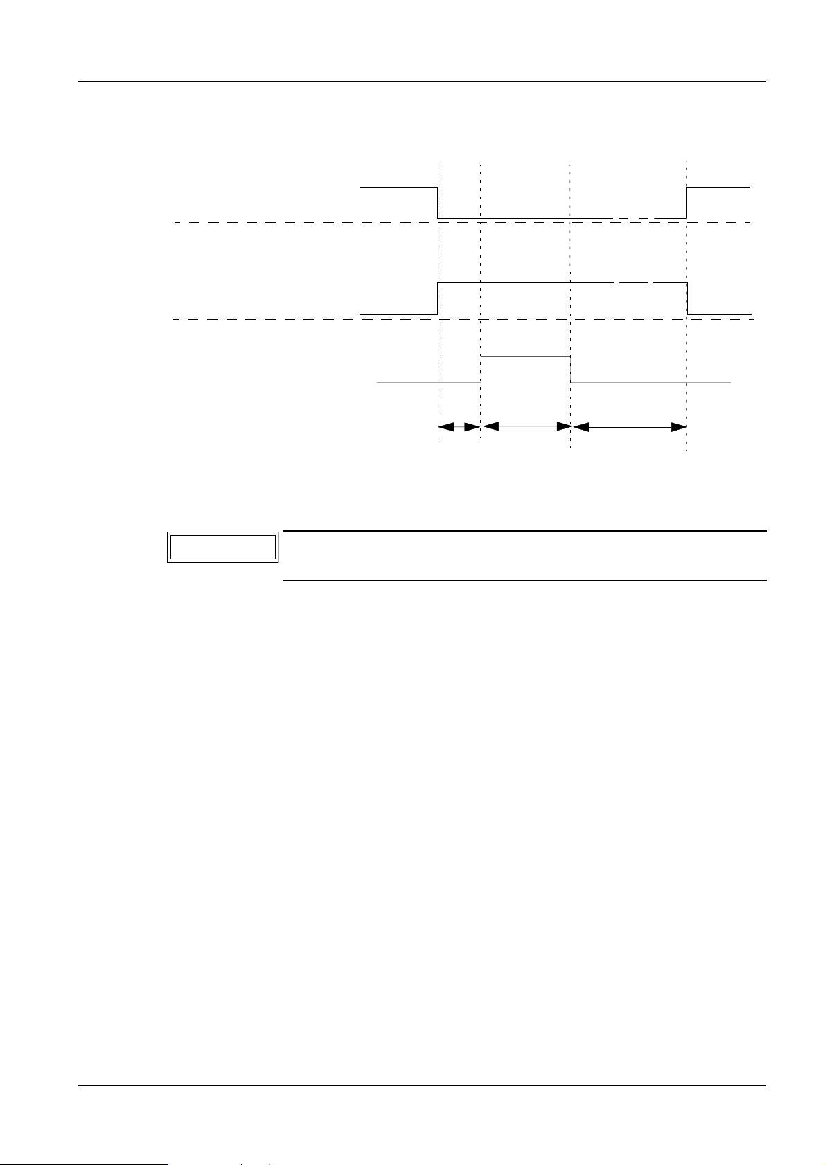
Timing diagram 7
This timing diagram is for ref erence only .
Monitor B, BAS, Image ON
Image OFF
Hardcopy, BAS, Image ON
Image OFF
Relay contact ON
Relay contact OFF
7 - 1
TV
TK
TN
TV = Precontact time default = 100 ms
TK = Contact time, default = 200 ms
TN = Postcontact time default = 5000
Changing the times 7
Adhere to the manufacturer’s instructions for the particular
camera being used.
Prerequisites 7
Input can only be done if there is a MEMOSKOP key board on han d.
The value s wil l only be displayed if there is a te x t module. However, "blind" programming
can also be done.
For UROSKOP and Multiline, plug D1 . X6 on the MEMOSKOP mus t be removed when
programming the times.
Opening Setup 7
• Press the [NEXT PAT] key.
• Next, press the [@] and [%] keys in sequence .
• Press the [CTRL] + [S] keys simultaneously.
• A list of numbers will be displayed on the monitor.
Changing the precontact time TV 7
• Enter the following : 00006506 **
**
means in HEX code: 01 = 100 ms, 02 = 200 ms, 32 = 5000 ms.
• Then press the [CTRL] + [E] keys simultaneously.
• Then, depending on the requirement, program the contact time TK and/or postcontact
time TN or exi t the Hardcopy Setup (refer to the section " Exit Setup " ).
Siemens AG RX57-029.061.01 Page 1 of 4 MEMOSKOP 2/3/50/100/SUB
Medical Engineer ing Rev. 02 10.97 TD SD 24
Page 24

7 - 2 Laser camera timing (not for MEMOSKOP 2)
Changing the contact time TK 7
• Enter the following numbers: 00006508 **
**
means in HEX code: 01 = 100 ms, 02 = 200 ms, 32 = 5000 ms.
• Then press the [CTRL] + [E] keys simultaneously.
• Then, depending on the requirement, program the precontact time TV and/or the
postcontact time TN or exit the Hardcopy Setup (refer to the section "Exit Setup ").
Changing the postcontact time TN 7
• Enter the following numbers: 0000650A **
**
means in HEX code: 01 = 100 ms, 02 = 200 ms, 32 = 5000 ms
• Then press the [CTRL] + [E] keys simultaneously.
• Then, depending on the requirement, program the precontact time TV and/or the
contact time TK or exit th e Hardcopy Setup ( refer to the section "Exit Setup ").
Exit Setup 7
• Press the [@] and [%] keys in sequence.
• Switch the unit off and then back on.
After switching the unit back on, the new Hardcopy timing will be valid.
• If plug D1.X6 was removed from the MEMOSKOP, reconnect it.
MEMOSKOP 2/3/50/100/SUB RX57-029.061.01 Page 2 of 4 Siemens AG
Rev. 02 10.97 TD SD 24 Medical Engineering
Page 25

Laser camera timing (not for MEMOSKOP 2) 7 - 3
Video timin g 7
Hardcopy Output, 525 / 60 Hz, MEMOSKOP 3, 50, SUB
Horizontal Frequency 15,750 kHz or pixels
Horizontal Line Time 63,492 msec or 853,33 pixels
Horizontal Sync Tip 4,4643 msec or 60,00 pixels
Horizontal Back Porch 12,21 msec or 164,1 p ixels
Horizontal Active Video 38,0952 msec or 512,00 pixels
Horizontal Front Porch 8,72 msec or 117,2 pixels
Horizontal Blanki ng 25,3968 msec or 341,33 pixels
Vertical Field Frequency 60,000 Hz
Vertical Field Time 16,6667 msec or 262,5 lines
Vertical Sync Tip 0,1905 msec or 3,0 lines
Vertical Back Porch 1,524 msec or 24,0(24,5) lines
Vertical Field Active Video 14,0952 msec or 222,0 lines
Vertical Front Porch 0,825 msec or 13,0(13,5) lines
Vertical Field Blanking 2,5397 msec or 40,0(41,0) lines
Interlaced Fields Yes/-Image Circ le 509 x 466 (H -pixel x V-pixel)
Ext. Pixel Clock Frequency MHz
Pixel Clock Image 13,44 MHz 1 pixel = 74,404762 ns
Pixel Clock Text 13,44 MHz
Pixel Aspe c t Ratio 0,916:1 (width/height)
Memory 512 x 444 (H -pixel x V-pixel)
Siemens AG RX57-029.061.01 Page 3 of 4 MEMOSKOP 2/3/50/100/SUB
Medical Engineer ing Rev. 02 10.97 TD SD 24
Page 26

7 - 4 Laser camera timing (not for MEMOSKOP 2)
Hardcopy Output, 625 / 50 Hz, MEMOSKOP 3, 50, SUB
Horizontal Frequency 15,625 kHz or pixels
Horizontal Line Time 64,000 msec or 853,33 pixels
Horizontal Sync Tip 4,500 msec or 60,00 pixels
Horizontal Back Porch 12,800 msec or 170,67 pixels
Horizontal Active Video 38,400 msec or 512,00 pixels
Horizontal Front Porch 8,300 msec or 110,67 pixels
Horizontal Blanking 25,600 msec or 341,33 pixels
Vertical Field Frequency 50,000 Hz
Vertical Field Time 20,000 msec or 312,5 lines
Vertical Sync Tip 0,160 msec or 2,5 lines
Vertical Back Porch 2,272 msec or 35,5(36,0) lines
Vertical Field Active Video 16,384 msec or 256,0 lines
Vertical Front Porch 1,152 msec or 18,0(18,5) lines
Vertical Field Blanking 3,584 msec or 56,0(57,0) lines
Interlaced Fields Yes/-- or
Image Circ le 496 x 548 (H -pixel x V-pixel)
Ext. Pixel Clock Frequency MHz
Pixel Clock Image 13,33 3 MHz 1 pix el = 75 ns
Pixel Clock Text 13,333 MHz
Pixel Aspect Ratio 1,105:1 (width/height)
Memory 512 x 512 (H -pixel x V-pixel)
MEMOSKOP 2/3/50/100/SUB RX57-029.061.01 Page 4 of 4 Siemens AG
Rev. 02 10.97 TD SD 24 Medical Engineering
Page 27

Changes as compared to previous versions 8
All chapte rs all pages Layout updated
and page b reaks changed.
Chapter 0 Revision lev el increase d.
Table of content s adjusted.
8 - 1
Chapter 1 Page 1
Page 2
Chapter 4 Page 2 Print numb er changed.
Chapter 5 Page 2 Print numb er changed.
Chapter 6 Page 2
Page 5
Page 6
Chapter 7 New chapter added.
Chapter 8 Page 1 Contents updated.
Print numb er and item nu m ber changed.
Reference to TI 236, ... in ARTD ... changed.
Print number changed.
Table updated.
Fig.3 remov ed.
TD SD 24 / Wendt
TD SD 34 / Schlee
SMS Iselin / O’D onnell
Siemens AG RX57-029.061.01 Page 1 of 2 MEMOSKOP 2/3/50/100/SUB
Medical Engineer ing Rev . 02 10.97 TD SD 34
Page 28

8 - 2 Changes as compared to previous versions
This page int entionally left blank.
MEMOSKOP 2/3/50/100/SUB RX57-029.061.01 Page 2 of 2 Siemens AG
Rev. 02 10.97 TD SD 34 Medical Engineering
 Loading...