

Page 1
1Fläkt Woods 8822 GB 2011.09
Specifi cations are subject to alteration without notice
Installation & maintenance
Control equipment
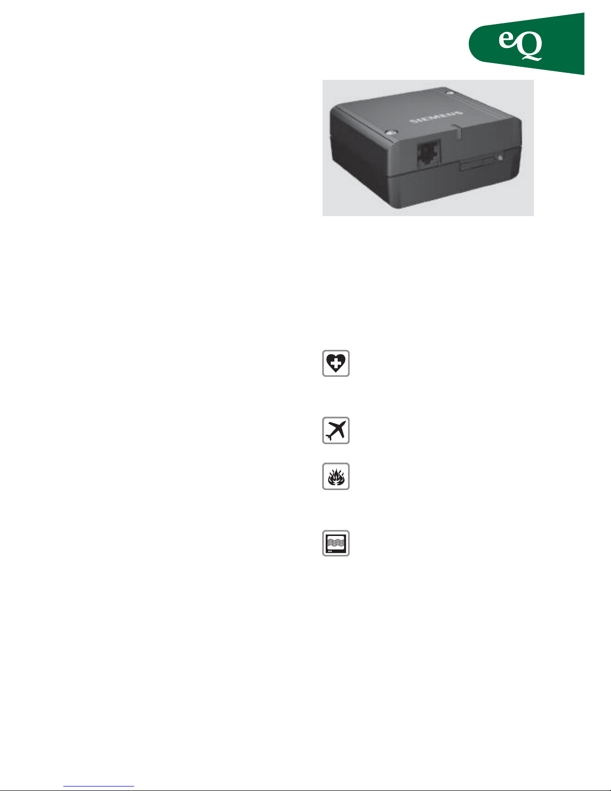
GPRS-modem MC35T
A robust GPRS and dual band GMS modem
with standard interfaces for remote monitoring
and alarm sending.
Product features
• Dual-band EGSM900 and GSM1800
• GPRS multi-slot class 8
• GPRS mobile station class B
• Compliant to GSM phase 2/2+
• Output power
• SIM application tool kit
• Supply voltage range 8V...30V
• Dimensions: 65 x 74 x 33 mm
Data
• CSD up to 14.4 kbps
• USSD
• Non transparent mode
• V.110
• GPRS: max 85.6 kbps (downlink)
• Coding schemes CS1, CS2, CS3, CS4
• PPP-stack
SMS
• Point-to-point MT and MO
• SMS cell broadcast
• Text and PDU mode
Certifi cation
• R & TTE
• GCF approval
Interfaces
• Plug-in power supply
• Handset audio interface
• Mini-Sim Card reader
• Antenna connector FME (male)
• V.24/V.28 interface on the 9-terminal
Sub-D-socket
• Operationg status LED
• Ignition lead on the 6-pin Western connector
Scope of supply
• MC35 Terminal
• User guide
Safety information
Radio devices have limitations in the vincinity of
electronic devices:
Switch the TC35 Terminal off when
you are in a hospital or near medical
devices like pacemakers or hearing aids.
The Terminal may interfere with the
operation of these devices.
Swith the TC35 Terminal off when fl ying.
Secure it so that cannot be switched on
inadevertently.
Switch the TC35 Terminal off when you
are near petrol stations, fuel depots,
chemical plants or blasting operations.
The Terminal can disturb the operation of
technical equipment.
Interfaces can occur if the devices is used
near televisions, radios or PCs.
In order to avoid possible damage, we
recommend that you only urse the
specifi ed accessories. These have been
tested and shown to work well with the
Terminal. However, the warranty does not
cover these accessories.
Page 2
2Fläkt Woods 8822 GB 2011.09
Control equipment
Specifi cations are subject to alteration without notice
Installation & maintenance
The warranty does not apply in the event
of improper use.
Product description
The TC35 Terminal is a compact GSM modem for
the transfer of data, voice, SMS and faxes in GSM
networks. Industrial standard interfaces and an
integrated SIM card reader mean it can be used
rapidly, easily and universally as a dual band
GSM Terminal. Its performance band width and
the robust housing make it easier to quickly implement new applications in areas such as telemetry and telematics.
The features, functions and interfaces of the GSM
Terminal TC35 T are described below.
The functionality of the Terminal corresponds to
the features of the TC35 module, to which a SIM
card reader, an
RS232 interface, an analog interface for the handset interface and a greater supply voltage range
have been added.
All the external interfaces of the GSM Terminal
TC35 T are integrated permanently in the housing.
The plug-in connections are standardized and
suitable for use under vibration.
Safety and installation installation
• The Terminal should be installed and set up
only by qualifi ed personnel.
• Connect a fast 1.25A fuse to the incoming line for
the positive supply voltage to protect the Terminal.
• If a power supply unit is used to supply the
TC35 Terminal, it must meet the demands placed
on SELV circuits in accordance with EN60950.
When using batteries and accumulators, adhere to
the relevant regulations.
• The maximum permissible connection length
between the TC35 Terminal and the supply source
is 3m.
Attaching the terminal
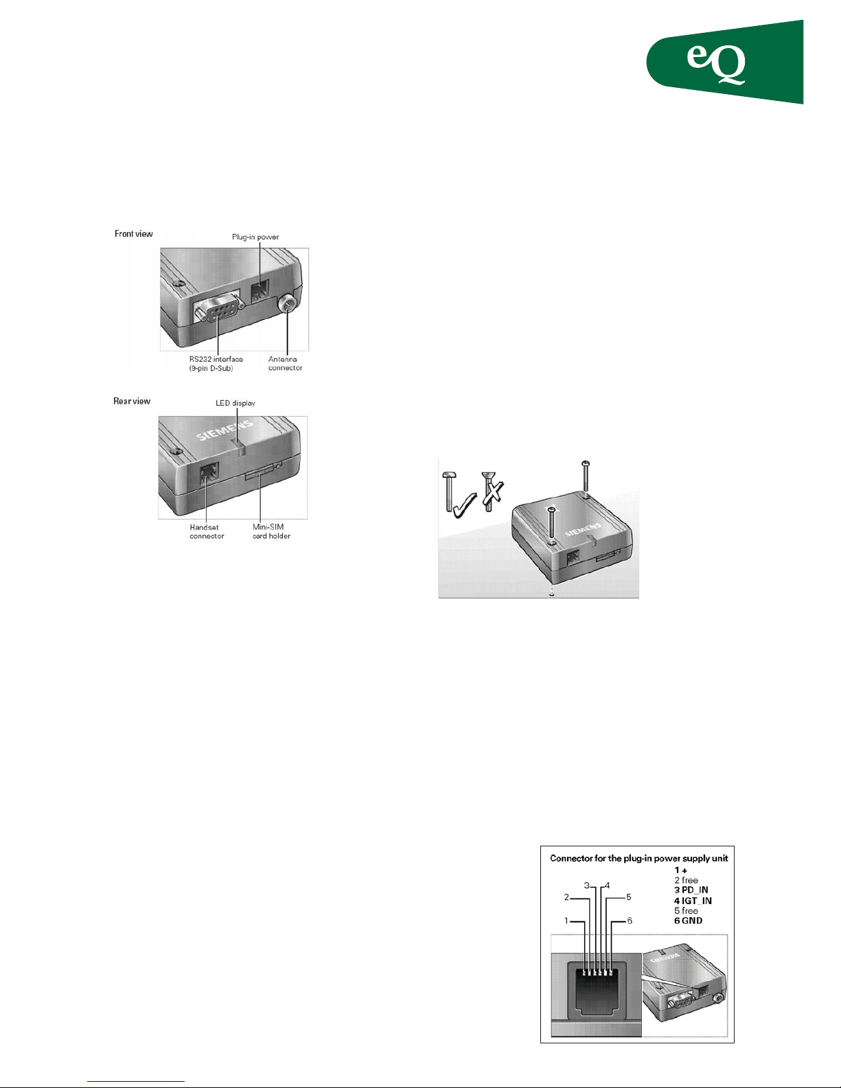
The TC35 Terminal can be attached with two
screws. Use screws approx.50 mm long and Ø.
Interface description
The following interfaces are available on the TC35Terminal:
• Connector for the plug-in power supply unit
• Handset connector (handset not available for
Fläkt Woods products)
• Mini-SIM card holder
• Antenna connector FME (male)
• RS232 interface (V.24/V.28 on the D-Sub socket)
Plug-in power supply unit
The TC35 Terminal receives its power supply in a
wide voltage range (+8 V ... +30 V) via the power
supply connectors. Two
additional
control lines
are used for
switching the
Terminal on/
off (resetting).
The connection
is implemented by a 6-pin
Mini- Western
connector.
Page 3
3Fläkt Woods 8822 GB 2011.09
Specifi cations are subject to alteration without notice
Installation & maintenance
Control equipment
Use and operation
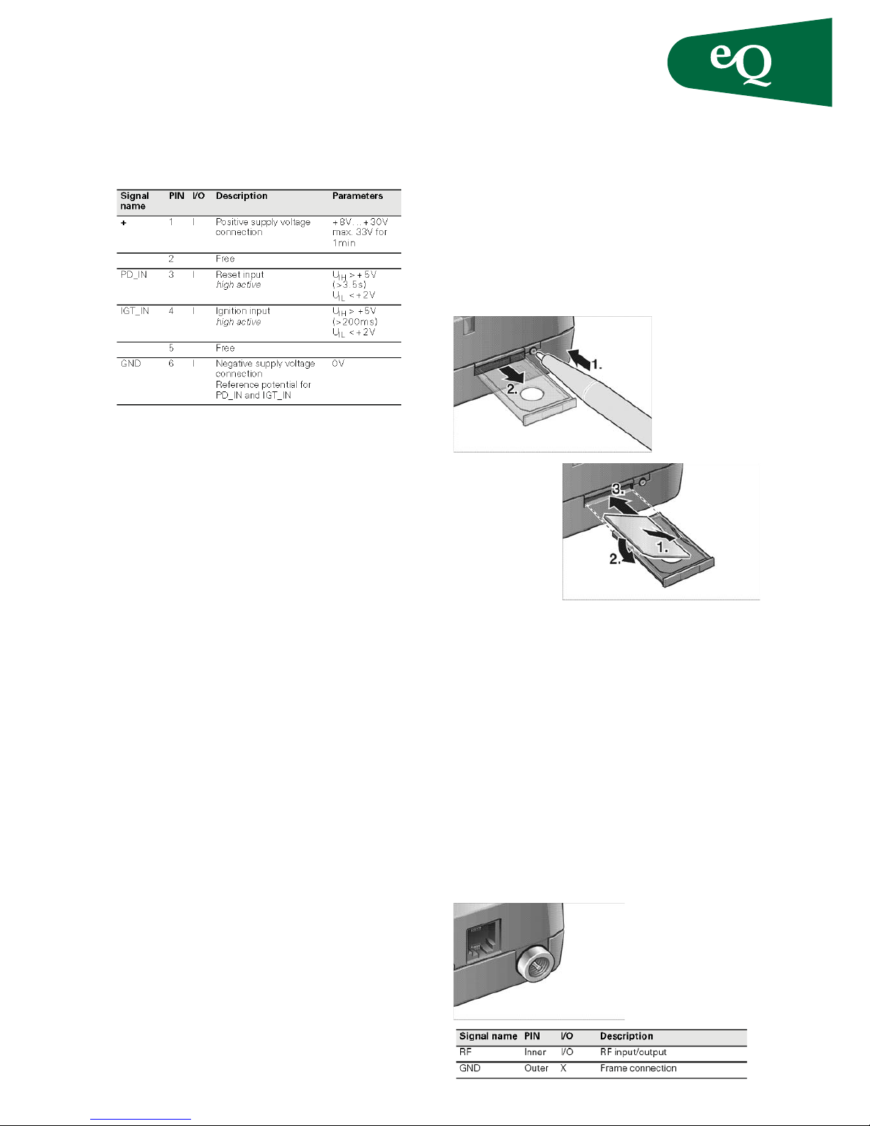
The power supply is implemented by the +- and
the GND wire. To switch the TC35 Terminal on,
proceed as follows:
• Either activate the DTR control line via the RS232
interface
• Or connect IGT_IN to +. This connection has
already been set up in the specifi ed plug-in power
supply unit
Polarity reversal protection
Polarity reversal protection is implemented by
means of a power diode. The diode has a reverse
voltage of 400V.
Overvoltage protection
Overvoltages are suppressed by a Zener diode after
the polarity reversal protection diode.
Fuses
A permanently installed, non-replaceable fuse in
the TC35 Terminal ensures electrical safety in the
event of faults. Connect a fast 1.25A fuse to the
supply line of the positive supply voltage for general protection of the Terminal.
SIM card connector
The connector is intended for 3V SIM cards in
accordance with GSM11.12 phase 2 to operate the
Terminal. The SIM card (3V type) must be inserted
in the card holder to put the TC35 Terminal into
operation.
1. Make sure that there is no voltage applied to the
TC35 Terminal.
2. Operate the eject mechanism (yellow pin next to
the card holder) to open the card holder by
pressing it down with a pen, for example.
3. Insert the SIM card in the SIM card holder and
push it back into the housing.
Use and operation
A SIM card holder from Molex with a SIM_IN contact is used. Only when the card holder is inserted
is the switched closed. The card can only be replaced when the GSM engine is in the POWER DOWN
state.
Interference immunity
Electrostatic discharge requirements in accordance
with ETS 300-342-1
Antenna connector FME (male)
A dual band antenna (GSM 900/1800) can be connected to the RF interface. The connection is implemented as a 50 FME (male) coaxial jack.
Antenna connector
Page 4
4Fläkt Woods 8822 GB 2011.09
Control equipment
Specifi cations are subject to alteration without notice
Installation & maintenance
Transmission type and method
• Digitally modulated RF burst signal
• GMSK in accordance with GSM05.04
• Half duplex
• Bidirectional
Interference immunity
• Electrostatic discharge requirements in
accordance with ETS 300-342-1
• Electrical fast transient burst requirements
(cable is >3m)
• Surge immunity requirements not specifi ed
• Electrostatic discharge requirements in
accordance with ETS 300-342-1
• Immunity RF common mode 0.15–80 MHz in
accordance with ETS300-342-1
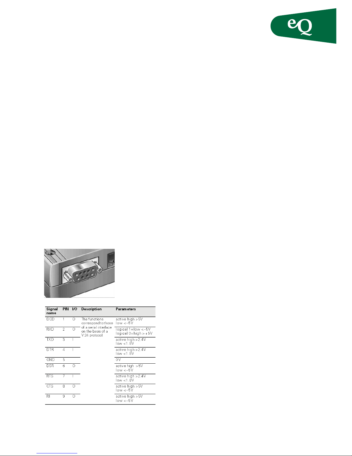
RS232 interface
The RS232 interface is the interface for the application software and the connection to the PC. The
customer application communicates with the TC35
Terminal or the TC35 GSM engine by means of
ATcellular commands. The RS232 interface is implemented as a 9-pin D-Sub socket with a screw fi tting.
RS232 interface – 9-pin D-Sub
Use and operation
In order to control the Terminal and transfer data,
the customer application (e.g. host computer) is
connected via the RS232 cable
Interference immunity
• The connecting cable must not exceed 1.8m in
length.
• Nominal signal range: ±15V
• Max. load current 1A
• Electrical fast transient burst requirements not
specifi ed
• Surge immunity requirements not specifi ed
• Electrostatic discharge requirements in accor dance with ETS 300-342-1
• Immunity RF common mode 0.15–80MHz in
accordance with ETS300-342-1
Startup
Before startup, the components required for your
application must be connected. The SIM card must
be inserted in a de-energized state.
The TC35 Terminal is ready for operation when
supply voltage is applied and the ignition line is activated. If the recommended plug-in power supply
unit is used, the ignition line is already connected
to the supply voltage line, and the TC35 Terminal
is thus immediately switched to the active state. It
starts the network search and registers with network operator. Please read the following conditions
for switching the Terminal on and off:
Switching on Terminal
Simply applying supply voltage (+ to pin 1 and
GND to pin 6) alone is not enough to switch on the
TC35 Terminal.
It can be switched on in two different ways:
Activation of the IGT_IN ignition signal on the
power supply connection
The switching regulator is switched on with the
IGT_IN=high signal. When the switching regulator
is switched on, VBAT is generated as the operating
voltage for the GSM module. This still does not
activate the GSM module. Triggered by VBAT, a
transistor switch generates the IGT ignition signal
with a delay of approx. 100ms for the GSM module.
Only then is it switched on. (It exits the POWER
DOWN operating state.)
In its energized state, the GSM module provides the
supply voltage (VDD). VDD ensures that the switching regulator remains on, even when its closing
condition is lost (i.e. IGT_IN=low).
Explanation:
VBAT=operating voltage for the GSM module
VDD=supply voltage from the module
Page 5
5Fläkt Woods 8822 GB 2011.09
Specifi cations are subject to alteration without notice
Installation & maintenance
Control equipment
Activation of the RS232 control line DTR
The TC35 Terminal can be switched on in the same
way as via IGT_IN by activating the RS232 control
line DTR (high signal).
Note
The TC35 Terminal is switched on immediately
using the recommended plug in power supply unit
(see the above explanation on startup).
Switching off / resetting the Terminal
The Terminal can be switched off in two different
ways:
Using a software command by means of an AT
command.
A software shutdown via an AT command is
always advisable for a controlled shut down of the
TC35 Terminal. In this case, the GSM module signs
off before the watchdog condition results in the
specifi c switching off of the supply voltages.
Activation of the PD_IN reset signal on the power
supply connection.
The POWERDOWN line on the GSM module is
connected to the watchdog input pin of the power
supply ASIC, which can only be switched off by
changing the watchdog condition. To do this, the
PD_IN Terminal reset line is active (high) for at
least 3.5s. This results in immediate, ”hard” disconnection, with the TC35 Terminal unable to sign off
correctly from the base station in the STANDBY
and TALK operating states .
In the case of this hardware shutdown, the software
is no longer able to respond before the voltage is
switched off. This corresponds to a direct, unannounced disconnection of the operating voltage. In
the application you can switch off or reset the module without interrupting the input voltage supply
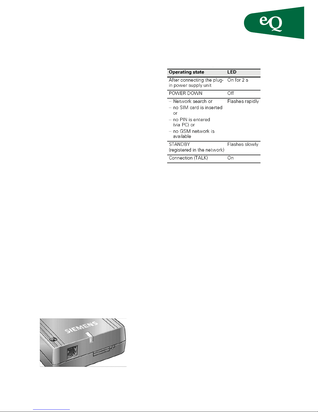
Operating states / LED
The LEDs display the following operating states of
the Terminal.
Note:
Usually, the network search takes only a few seconds till the Terminal is registered. If the fl ashing
continues, this means that no SIM card is inserted,
no PIN number is entered or no GSM network is
available
POWER DOWN
Once the operating voltage is applied (+ and GND),
the TC35 Terminal is in the POWER DOWN state.
The operating voltage for the GSM module is
disconnected (the switching regulator is off). In
other words, the software of the GSM module is not
active.
A transition to the POWER DOWN state always
occurs in the following circumstances:
• When the Terminal (module) is shut down by
means of AT commands (e.g. sleep mode).
• When the external reset line is active.
Network search (no SIM card, no PIN number, no
GSM network)
In the network search state, the TC35 Terminal searches for a GSM network. All the components in the
GSM Terminal (module) that are not required are
shut down in several stages by the energy-saving
software.
This state is reached:
• From the POWER DOWN state: by an active
ignition (on) signal at the power supply
connection or
• From the TALK or STANDBY state: when the
network is lost (out of range)
Page 6
6Fläkt Woods 8822 GB 2011.09
Control equipment
Specifi cations are subject to alteration without notice
Installation & maintenance
Standby
In the STANDBY state, the TC35 Terminal is ready
to send and receive and registered in the network.
Paging is performed with the GSM network in
order to obtain synchronization with the GSM network (repetition rate dependent on the BSPA_Mutiframe=2...9 parameter). All the components that are
not required are shut down in several stages by the
energy saving software. Power consumption in this
state depends on the current network availability.
Talk
In TALK mode a connection has been established
between two subscribers via the GSM network.
Power consumption is at the maximum and depends on the GSM network availability and several
connection settings (e.g. DTX off/on, FR/EFR/HR,
hopping sequences and antenna coupling).
AT command control
The TC35 Terminal is controlled and programmed
by means of AT commands. The AT command
structure corresponds to the TC35 module used.
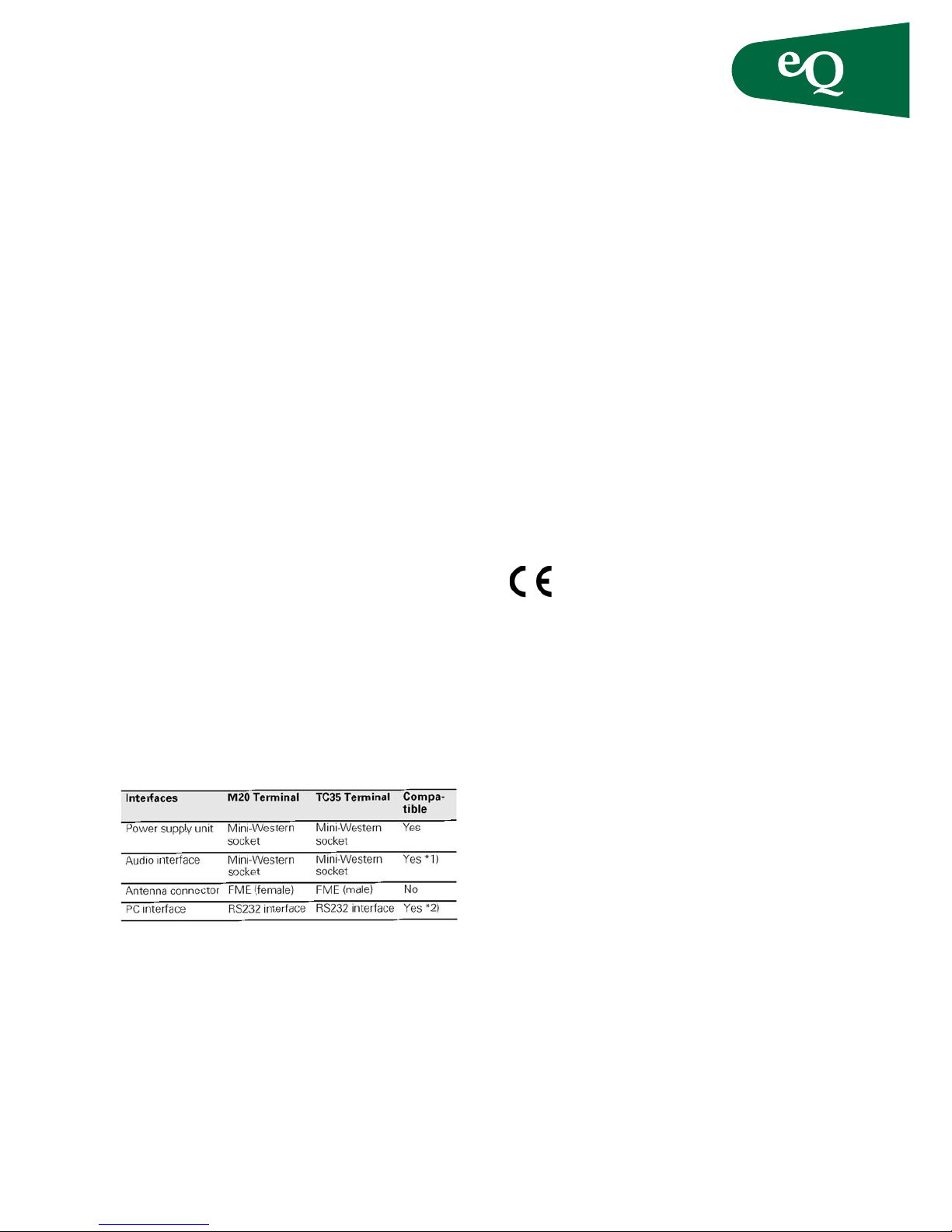
Compatibility
Compatibility with the predecessor, the M20
Terminal. The direct predecessor of the TC35 Terminal is the M20 Terminal. The antenna connector is
not compatible. The modifi ed version (passive ver-
sion) of the Votronic handset must be operated at
the audio interface in accordance with HH-SI-30.3/
V1.1/0.
*1) The studio interface is no longer available with the
TC35 Terminal.
*2) All the control lines are brought out of the TC35T.
Software:
The command set of the M20 Terminal has been
modifi ed and extended for the TC35 Terminal and
is thus not 1:1 compatible. A migration paper with
the modifi cations is available at the ICM WM home
page on the Internet.
Certifi cation / maintenance
Certifi cation
The TC35 with its IMEI number is approved for
operation in GSM networks and complies with the
following EU directives:
• Directive 89/336/EEC on electromagnetic
compatibility
• Directive 98/13/EC, CTR 19 and CTR 20, on
telecommunications Terminal equipment
• Directive 98/13/EC, CTR 31 and CTR 32, on
telecommunications Terminal equipment
• Directive 73/23/EEC on low voltage, supplemen ted by Directive 93/68/EEC
Maintenance tips
• Treat the SIM card with the same care as your
credit card. Do not bend or scratch the SIM card
or expose it to static electricity.
• Wipe the Terminal housing with a moist or
antistatic cloth. Do not use a chemical cleaning
agent.
 Loading...