

Siemens LSPK372-PO, LSGK372-QO Datasheet
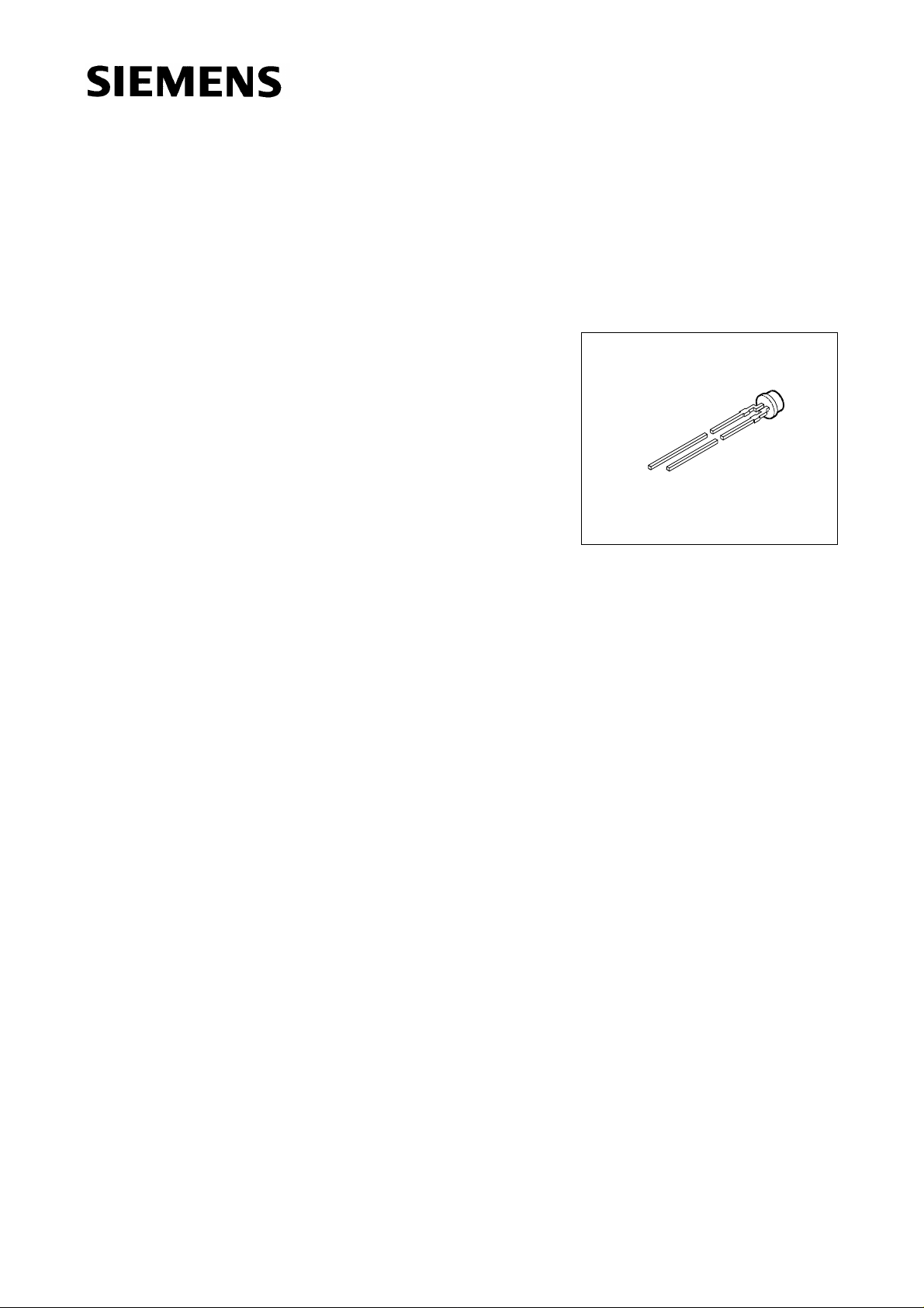
Super Multi ARGUS® LED
High-Current, 3 mm (T1) LED, Non Diffused
Besondere Merkmale
● farbloses, klares Gehäuse
● Kunststoffgehäuse mit spezieller Formgebung
● antiparallel geschaltete Leuchtdiodenchips
● besonders geeignet bei hohem Umfeldlicht durch erhöhten
Betriebsstrom (typ. 50 mA)
● hohe Signalwirkung durch Farbwechsel der LED möglich
● bei Einsatz eines äußeren Reflektors zur Hintergrundbe-
leuchtung von Leuchtfeldern und LCD-Anzeigen geeignet
● zur Direkteinkopplung in Lichtleiter geeignet
● gleichmäßige Ausleuchtung einer Streuscheibe (Weiß-
druck) vor dem äußeren Reflektor
● Lötspieße mit Aufsetzebene
● gegurtet lieferbar
● Störimpulsfest nach DIN 40839
LSG K372, LSP K372
VEX06712
Features
● colorless, clear package
● plastic package with a special design
● antiparallel chip
● appropriate for high ambient light because of the higher operating current (typ. 50 mA)
● high signal efficiency possible by color change of the LED
● in connection with an additional, custom built reflector suitable for backlighting of display panels
● for optical coupling into light pipes
● uniform illumination of a diffuser screen in front of the custom built reflector
● solder leads with stand-off
● available taped on reel
● load dump resistant acc. to DIN 40839
Semiconductor Group 1 11.96
LSG K372, LSP K372
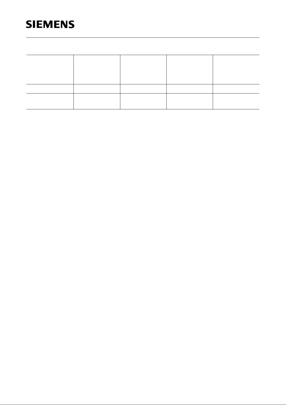
Typ
Type
Emissionsfarbe
Color of
Emission
Gehäusefarbe
Color of
Package
Lichtstrom
Luminous Flux
I
= 50 mA
F
Bestellnummer
Ordering Code
ΦV(mlm)
LSG K372-QO super-red / green colorless clear ≥ 100 (160 typ.) Q62703-Q2647
LSP K372-PO super-red /
colorless clear ≥ 40 (100 typ.) Q62703-Q2380
pure green
Streuung des Lichtstromes in einer Verpackungseinheit Φ
Streuung des Lichtstromes in einer LED Φ
1)
Bei MULTILED® bestimmt die Helligkeit des jeweils dunkleren Chips in einem Gehäuse die Helligkeitsgruppe
der LED.
Luminous flux ratio in one packaging unit Φ
Luminous flux ratio in one LED Φ
1)
In case of MULTILED®, the brightness of the darker chip in one package determines the brightness group of
the LED.
V max
/ Φ
/ Φ
V max
/ Φ
V max
≤ 3.0 (L*G K372), ≤ 4.0 (L*P K372).
V min
≤ 3.0 (L*G K372), ≤ 4.0 (L*P K372).
V min
≤ 2.0.
V min
V max
/ Φ
1)
V min
≤ 2.0.
1)
Semiconductor Group 2
LSG K372, LSP K372
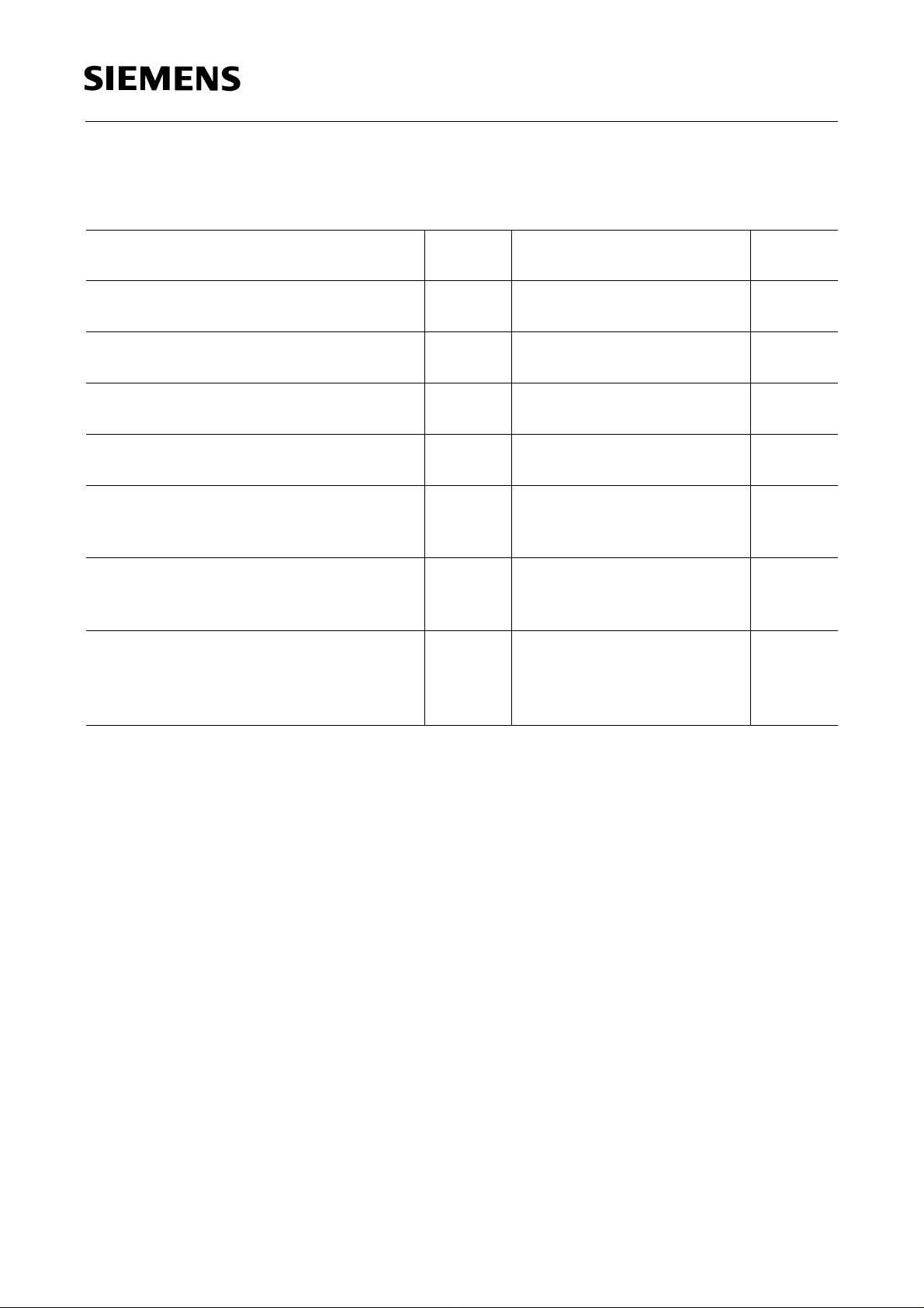
Grenzwerte
Maximum Ratings
1)
1)
Bezeichnung
Parameter
Betriebstemperatur
Operating temperature range
Lagertemperatur
Storage temperature range
Sperrschichttemperatur
Junction temperature
Durchlaßstrom
Forward current
Stoßstrom
Surge current
t ≤ 10 µs, D = 0.005
Verlustleistung
Power dissipation
T
≤ 25 °C
A
Wärmewiderstand
Termal resistance
Sperrschicht / Luft
Junction / air
Symbol
Symbol
T
op
T
stg
T
j
I
F
I
FM
P
tot
2)
R
th JA
Werte
Values
Einheit
Unit
– 55 ... + 100 ˚C
– 55 ... + 100 ˚C
+ 100 ˚C
75 mA
1A
240 mW
250 K/W
1)
Die angegebenen Grenzwerte gelten für den Chip, für den sie angegeben sind, unabhängig vom
Betriebszustand des anderen.
2)
Montiert auf Platine mit min. Anschlußlänge (bis Aufsatzebene, Lötfläche ≥ 16 mm2).
1)
The stated maximum ratings refer to the specified chip regardless of the other one’s status.
2)
Mounted on PC board with min. lead length (up to stand-off, pad size ≥ 16 mm2).
Semiconductor Group 3
 Loading...