

Siemens LSGT770-JL, LSGT770-HK, LSGT770-K Datasheet
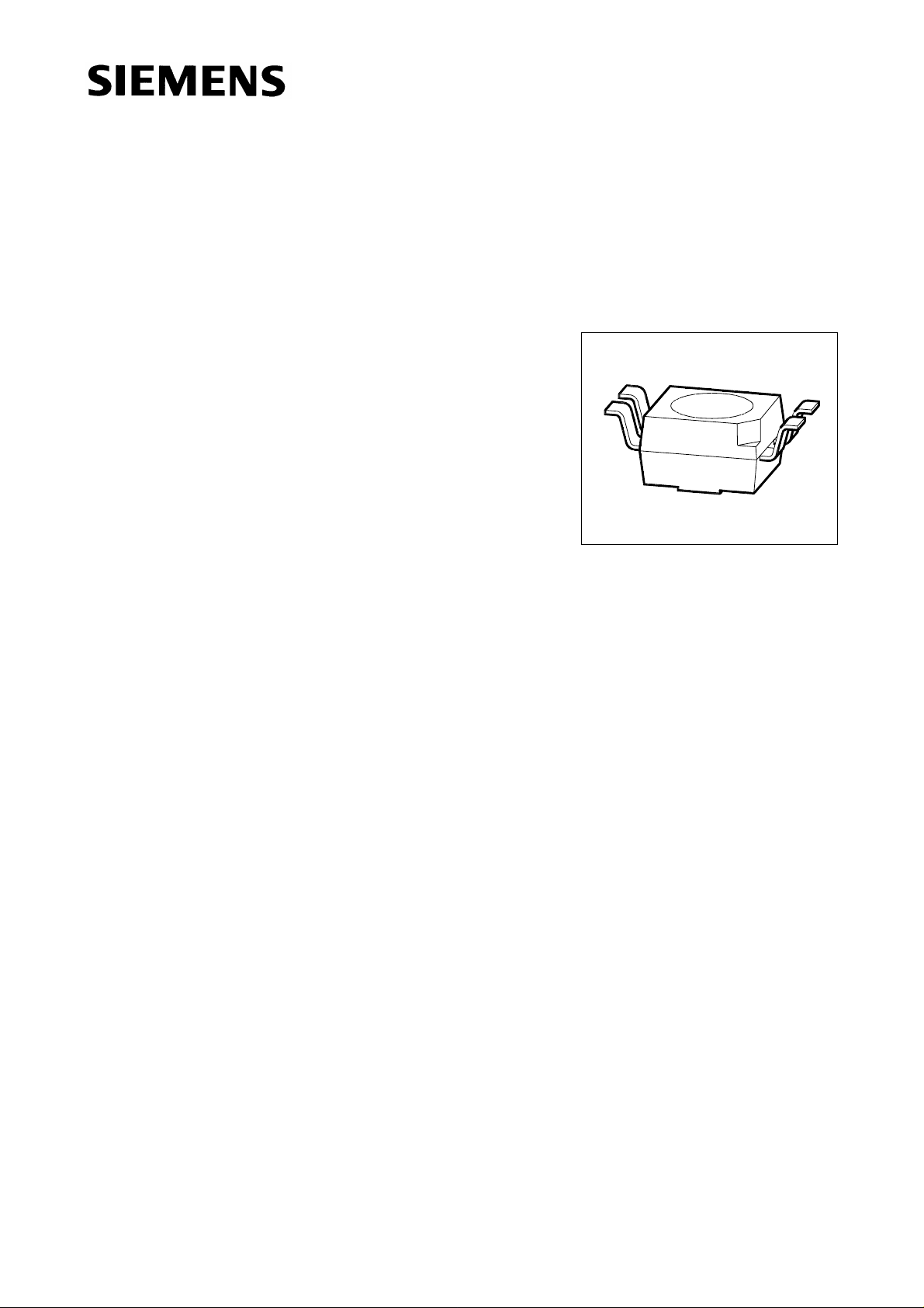
Multi TOPLED®RG LSG T770
Besondere Merkmale
● Gehäusebauform: P-LCC-4
● Gehäusefarbe: weiß
● als optischer Indikator einsetzbar
● zur Hinterleuchtung, Lichtleiter- und Linseneinkopplung
● beide Leuchtdiodenchips getrennt ansteuerbar
● hohe Signalwirkung durch Farbwechsel der LED möglich
● bei geeigneter Ansteuerung, Farbwechsel von grün über
gelb und orange bis super-rot möglich
● für alle SMT-Bestück- und Löttechniken geeignet
● gegurtet (12-mm-Filmgurt)
● Störimpulsfest nach DIN 40839
Features
VPL06908
● P-LCC-4 package
● color of package: white
● for use as optical indicator
● for backlighting, optical coupling into light pipes and lenses
● both chips can be controlled separately
● high signal efficiency possible by color change of the LED
● with appropriate controlling it is possible to change color
from green to yellow and orange to super-red
● suitable for all SMT assembly and soldering methods
● available taped on reel (12 mm tape)
● load dump resistant acc. to DIN 40839
Semiconductor Group 1 11.96
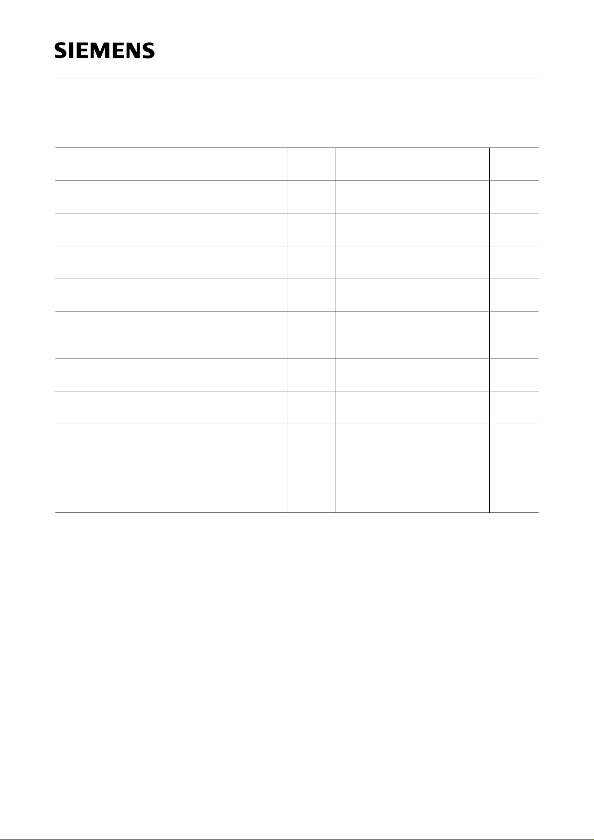
LSG T770
Typ
Emissionsfarbe
Farbe der
Lichtaustritts-
Lichtstärke
Lichtstrom
Bestellnummer
fläche
Type
LSG T770-HK
LSG T770-J
LSG T770-K
LSG T770-JL
Streuung der Lichtstärke in einer Verpackungseinheit I
Streuung der Lichtstärke in einer LED I
1)
Bei MULTILED® bestimmt die Helligkeit des jeweils dunkleren Chips in einem Gehäuse die Helligkeitsgruppe
der LED.
Luminous intensity ratio in one packaging unit I
Luminous intensity ratio in one LED I
1)
In case of MULTILED®, the brightness of the darker chip in one package determines the brightness group of
the LED.
Color of
Emission
super-red /
green
Color of the
Light Emitting
Area
Luminous
Intensity
I
= 10 mA
F
I
(mcd)
V
colorless clear 2.5 ... 12.5
4.0 ... 8.0
6.3 ... 12.5
4.0 ... 20.0
V max
V max
V max
/ I
/ I
V min
V min
V max
≤ 3.0.
/ I
≤ 3.0.
V min
/ I
V min
≤ 2.0.
Luminous
Flux
I
= 10 mA
F
ΦV(mlm)
18 (typ.)
30 (typ.)
-
1)
≤ 2.0.
1)
Ordering Code
Q62703-Q2567
Q62703-Q2893
Q62703-Q2894
Q62703-Q2895
Semiconductor Group 2
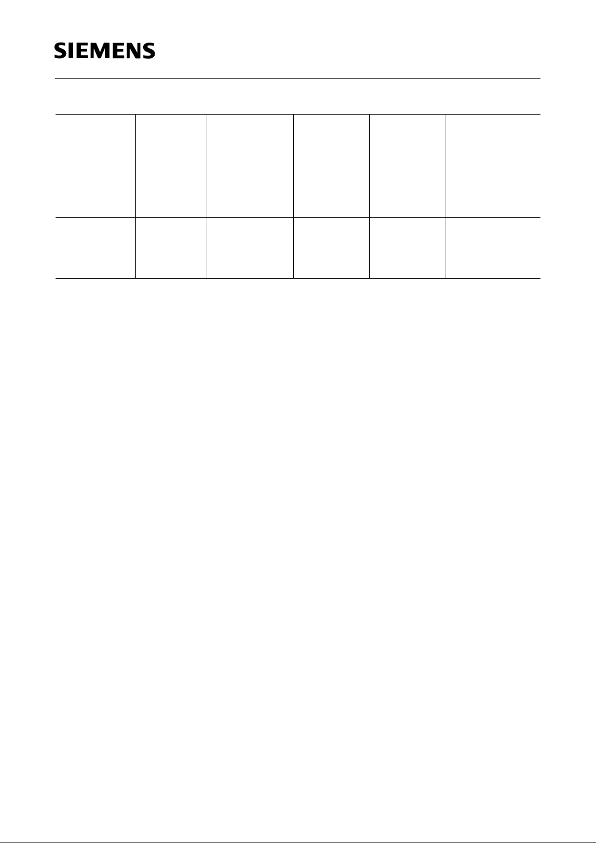
Grenzwerte
Maximum Ratings
LSG T770
Bezeichnung
Parameter
Betriebstemperatur
Operating temperature range
Lagertemperatur
Storage temperature range
Sperrschichttemperatur
Junction temperature
Durchlaßstrom
Forward current
Stoßstrom
Surge current
t ≤ 10 µs, D = 0.005
Sperrspannung
Reverse voltage
Verlustleistung
Power dissipation
Wärmewiderstand
Thermal resistance
Sperrschicht / Umgebung
Junction / air
)
Montage auf PC-Board*
mounted on PC board*) (pad size ≥ 16 mm 2)
(Padgröße ≥ 16 mm 2)
Symbol
Symbol
T
op
T
stg
T
j
I
F
I
FM
V
R
P
tot
1)
R
th JA
2)
R
th JA
Wert
Value
Einheit
Unit
– 55 ... + 100 ˚C
– 55 ... + 100 ˚C
+ 100 ˚C
30 mA
0.5 A
5V
100 mW
480
650
K/W
K/W
)
PC-board: FR4
*
1)
nur ein Chip betrieben
2)
beide Chips betrieben
1)
one system only
2)
both systems on simultaneously
Notes
Die angegebenen Grenzdaten gelten für einen Chip.
The stated maximum ratings refer to one chip.
Semiconductor Group 3
 Loading...