

Siemens Low-Voltage Power Installation Manual
© Siemens 2020
Catalog
Extract
LV 10
Edition
04/2020
SENTRON • SIVACON • ALPHA
Low-Voltage Power
Distribution and Electrical
Installation Technology
Switching Devices
siemens.com/lowvoltage

© Siemens 2020
Making sure power makes
its way
Consistent, safe and intelligent low-voltage power
distribution and electrical installation technology
Whether industries, infrastructures or buildings: Each environment depends
on a reliable power supply.
Which is why products and systems featuring maximum safety and optimum
efciency are in demand. This comprehensive portfolio for low-voltage power
distribution and electrical installation technology covers every requirement –
from the switchboard to the socket outlet.
We are there when you need us
Your personal contact can be found at
www.siemens.com/lowvoltage/contact
Catalog LV 10 · 04/2020
You will nd the latest edition and all future editions
in the Siemens Industry Online Support at
www.siemens.com/lowvoltage/catalogs
Refer to the Industry Mall for current prices
www.siemens.com/industrymall
The products and systems listed in this catalog are developed and
manufactured using a certied quality management system in
accordance with DIN EN ISO 9001:2008.
Technical data
The technical specications are for general information purposes only.
Always heed the operating instructions and notices on individual products
during assembly, operation and maintenance.
All illustrations are not binding.
© Siemens 2020

© Siemens 2020
SENTRON · SIVACON · ALPHA
Low-Voltage Power Distribution and
Electrical Installation Technology
Protecting
Protecting, Switching and Isolating
Switching and Isolating
Measuring and Monitoring
Introduction
Air Circuit Breakers 1/1
Molded Case Circuit Breakers 2/1
Miniature Circuit Breakers
Residual Current Protective Devices / Arc Fault Detection Devices (AFDDs) 4/1
Switching Devices 5/1
Overvoltage Protection Devices 6/1
Fuse Systems
Switch Disconnectors
Transfer Switching Equipment and Load Transfer Switches
Measuring Devices, Power Monitoring and Digitalization Solutions 10/1
I/2
3/1
7/1
8/1
9/1
I
1
2
3
4
5
6
7
8
9
10
Distribution
Monitoring Devices 11/1
Transformers, Power Supply Units and
Busbar Systems
Terminal Blocks
Power Distribution Boards, Motor Control Centers and Distribution Boards
Busbar Trunking Systems
System Cubicles, System Lighting and System Air-Conditioning
Appendix A/1
Socket Outlets 12/1
13/1
14/1
15/1
16/1
17/1
11
12
13
14
15
16
17
A

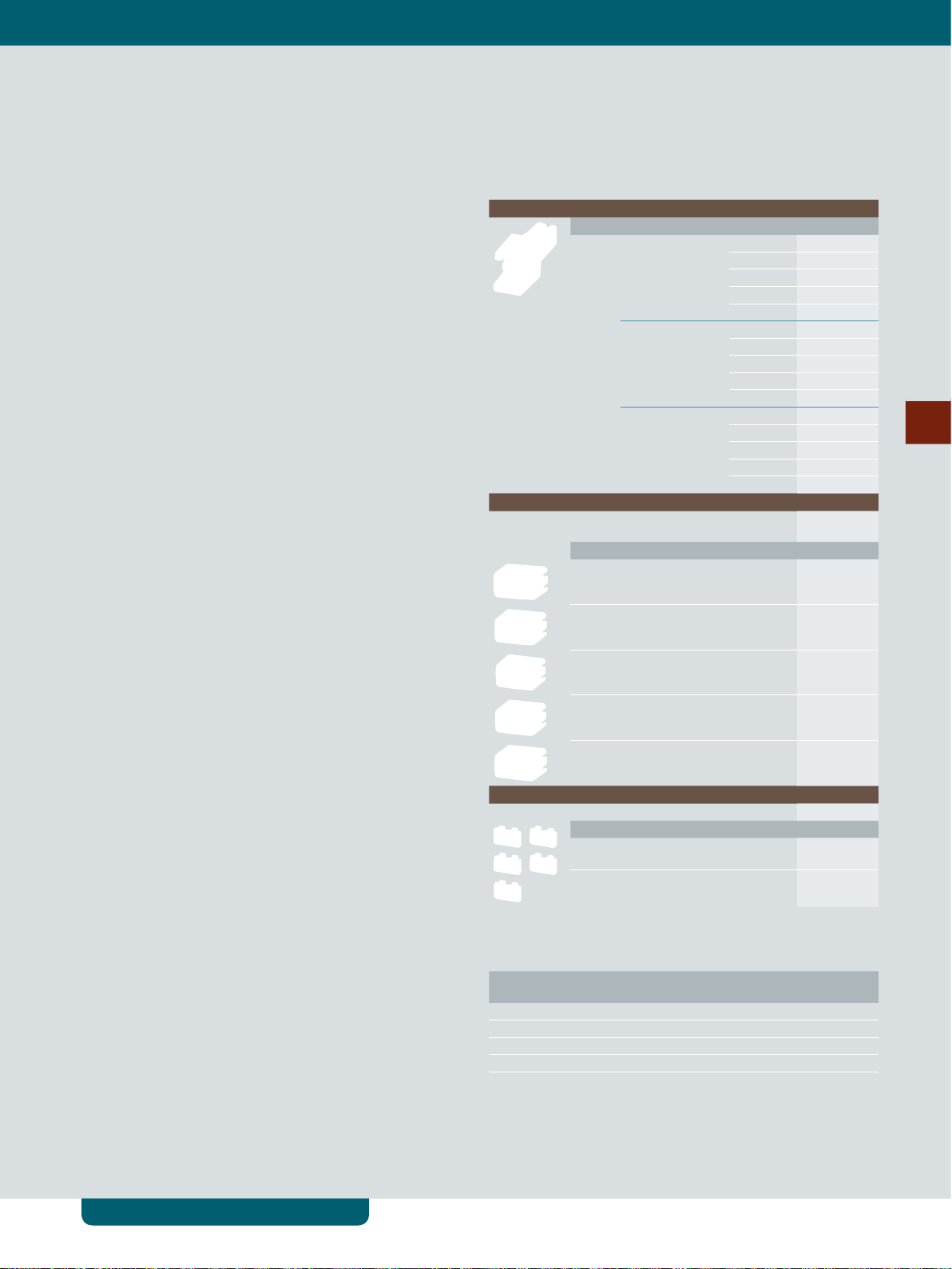
Switching Devices
© Siemens 2020
Electrical switching –
on the safe side
Control and automatic functions always employ
electrical switching.
Remote control switches for pulse controls,
switching relays, or Insta contactors switch
electrical loads.
Our low-voltage circuit protection technology
offers a wide variety of contact versions and rated
currents for the different requirements of these
devices.
Safety, convenience and energy savings – these
characterize automatic switching.
Switching Devices
All the information you need 5/2
System overview 5/4
Installation switching devices 5/6
© Siemens 2020
5TE8 control switches 5/6
5TE48 pushbuttons 5/8
Switching Devices
5
5TE58 light indicators 5/10
5TE81/82 On/Off switches 5/12
5TL1 On/Off switches 5/14
5TE DC isolator 5/16
5TE busbars 5/18
5TT41 remote control switches 5/20
5TT44 remote control switches 5/24
5TT4 auxiliary switches 5/26
5TT42 switching relays 5/28
5TT50 Insta contactors 5/30
5TT58 Insta contactors 5/32
5TT5 auxiliary switches 5/34
5TT3 soft-starting devices 5/35
Timers 5/36
7LF4 digital time switches 5/36
7LF5 mechanical time switches 5/42
7LF6 timers for buildings new 5/46
5TT3 timers for industrial applications 5/47
Siemens LV 10 · 04/2020
5/1

Switching Devices
|
All the information you need
© Siemens 2020
A multitude of additional information ... ... can be found in our online services
Information + ordering
All the important things at a glance
Information to get you started
For information about switching devices, please visit our
website
www.siemens.com/switching-devices
5
Contact persons in your region
Everything you need for your order
Refer to the Industry Mall for an overview of your
products
• Switching devices sie.ag/2m4eG5M
Direct forwarding to the individual products in the
Industry Mall by clicking on the Article No. in the catalog
or by entering this web address incl. Article No.
www.siemens.com/product?Article No.
We are there when you need us
You can nd your local contacts at
www.siemens.com/lowvoltage/contact
Your product in detail
The relevant tender specications can be found at
www.siemens.com/lowvoltage/tenderspecications
Use our conversion tool for quick and easy conversion to
Siemens products www.siemens.com/conversion-tool
5/2
Siemens LV 10 · 04/2020
Commissioning + operation
© Siemens 2020
All the information you need
|
Switching Devices
Your product in detail
The Siemens Industry Online Support portal provides
detailed technical information
www.siemens.com/lowvoltage/product-support
• Operating instructions
• Certicates
Engineering data for CAD or CAE systems are available in
the CAx Download Manager at
www.siemens.com/lowvoltage/cax
Manuals
Manuals are available for downloading in Siemens
Industry Online Support at
www.siemens.com/lowvoltage/manuals
• Conguration manual – Switching devices (45315361)
The fast track to the experts
Competent expert advice on technical questions with
a wide range of demand-optimized services for all our
products and systems.
Assistance with technical queries is provided at
www.siemens.com/lowvoltage/support-request
We offer a comprehensive portfolio of services.
You can nd your local contacts at
www.siemens.com/lowvoltage/contact
You can nd further information on services at
www.siemens.com/service-catalog
Technical overview – Switching devices
The fast way to get you to our online services
This page provides you with comprehensive information and links on switching devices
www.siemens.com/lowvoltage/product-support (109769083)
Siemens LV 10 · 04/2020
5/3
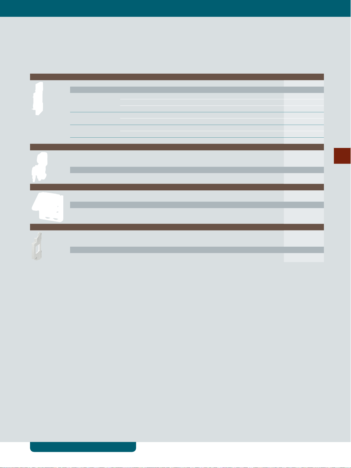
Switching Devices
|
System overview
System overview
Basic units and accessories
Installation switching devices
© Siemens 2020
5TE8
control switches
5TE48
pushbuttons
5TE58
light indicators
5TE81/82, 5TL1
On/Off switches, 5TE2
5TE
DC isolators
5TE
busbars
5TT41, 5TT44
remote control
switches
5
5TT4, 5TT5
auxiliary switches
5TT42
switching relays
5TT50, 5TT58
Insta contactors
5TT3
soft-starting devices
Accessories
Auxiliary switches
(AS)
Shunt trips
(ST)
Undervoltage
releases (UR)
Handle locking
devices
LEDs Caps/covers Connectors
Timers
7LF4 digital
time switches
7LF5 mechanical
time switches
7LF6 timers for
buildings new
Accessories
Holders
Note:
You will nd a detailed range of accessories with the basic units.
5/4
Siemens LV 10 · 04/2020
5TT3 timers for
industrial applications

© Siemens 2020
System overview
|
Switching Devices
5
Siemens LV 10 · 04/2020
5/5
Switching Devices
|
Installation switching devices
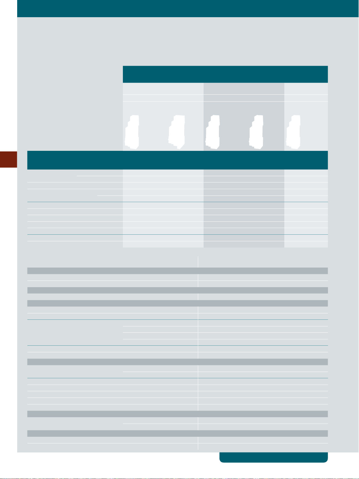
5TE8 control switches
© Siemens 2020
Control switches Two-way switches Group switches
with center
position
Rated operational current I
per conducting path
Rigid conductor cross-section
Flexible conductor cross-section,
20 A 20 A 20 A
e
1 … 6 mm
1 … 6 mm
2
2
1 … 6 mm
1 … 6 mm
2
2
1 … 6 mm
1 … 6 mm
2
2
with end sleeve
Contacts Ue AC Mounting
5
1 NO 48 V 1 MW 5TE8101-3 – – – –
230 V 1 MW 5TE8101 – – – –
2 NO 400 V 1 MW 5TE8102 – – – –
3 NO 400 V 1 MW 5TE8103 – – – –
1 NO + 1 NC 400 V 1 MW – – – 5TE8151 –
2 NO + 2 NC 400 V 1 MW – – 5TE8152 – –
3 NO + 1 NC 400 V 1 MW – – 5TE8153 – –
1 CO 230 V 1 MW – – 5TE8161 – –
2 CO 400 V 1 MW – – 5TE8162 – –
1 toggle switch 230 V 1 MW – – – – 5TE8141
2 toggle switches 400 V 1 MW – – – – 5TE8142
width
1.5 MW – 5TE8108 – – –
Auxiliary switches Auxiliary switches Auxiliary switches
Cannot be
retrotted
Mounted Cannot be
retrotted
Mounted Cannot be
retrotted
Further technical specications 5TE8
Standards
Standards IEC/EN 60947-3 (VDE 0660-107), IEC/EN 60669-1 (VDE 0632-1)
Approvals IEC/EN 60947-3 (VDE 0660-107), GB14048.3-2008 CCC
Supply
Rated power dissipation P
Contacts
Minimum contact load 10 V; 300 mA
Rated making/rated breaking capacity At p.f. = 0.65 60 A / 60 A
Rated short-time withstand current I
per conducting path at p.f. = 0.7
Thermal rated current I
Electrical/mechanical service life Actuations 10000 / 25000
Safety
Clearances Open contacts 2× >2 mm
Creepage distances >7 mm
Sealable switch position Yes
Separate handle locking device Yes
Rated short-circuit making capacity I
Rated impulse withstand voltage U
Connections
Terminals ± Screw (Pozidriv) PZ 1
Environmental conditions
Permissible ambient temperature –5 … +40 °C
Resistance to climate at 95% relative humidity Acc. to DIN 50015 45 °C
v
cw
th
cm
imp
Per pole 0.7 VA
Up to 0.2 s 650 A
Up to 0.5 s 400 A
Up to 1 s 290 A
Up to 3 s 170 A
20 A
Between the poles >7 mm
10 kA
>5 kV
Max. tightening torque 0.8 ... 1.0 Nm
5/6
Siemens LV 10 · 04/2020
System overview, page 5/4

Accessories
Auxiliary switches (AS)
Handle locking device
© Siemens 2020
Installation switching devices
• For right-hand-side retrotting with factory-tted brackets
Contacts Version Article No.
1 NO + 1 NC Standard 5ST3010
For low power 5ST3013
For low power (with diode) 5ST3013-0XX01
2 NO Standard 5ST3011
For low power 5ST3014
2 NC Standard 5ST3012
For low power 5ST3015
1 CO Standard 5ST3016
• To prevent undesired mechanical On/Off switching
• Sealable
• For padlock with max. 3 mm shackle
|
Switching Devices
Article No.
5ST3801
5
Spacer
Set of mixed caps
• Contour for modular devices with a mounting depth of 70 mm
• Can be snapped onto either side of the busbar for convenient cable routing
• Spacer is recommended for better heat dissipation
Article No.
5TG8240
• For manual changing of the luminous plates for the control switches
Article No.
5TG8068
System overview, page 5/4
Siemens LV 10 · 04/2020
5/7
Switching Devices
|
Installation switching devices
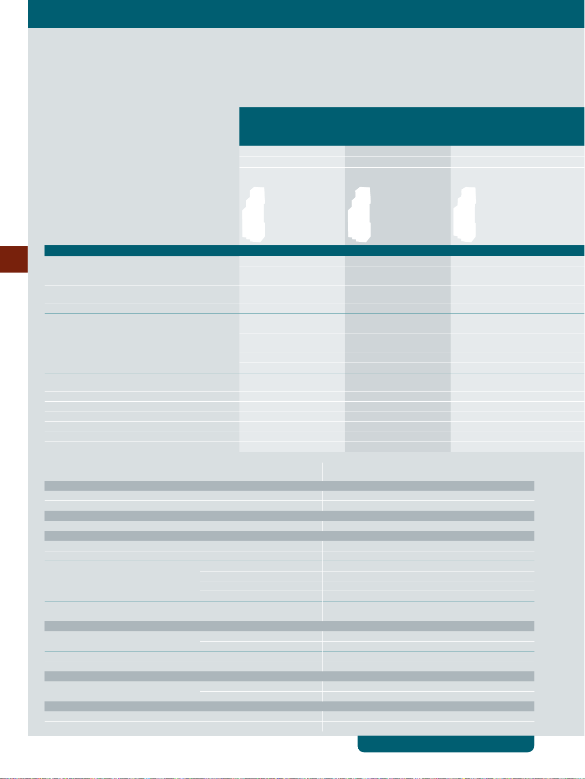
5TE48 pushbuttons
With/without LED
© Siemens 2020
Pushbuttons without
maintained-contact function
Pushbuttons with
maintained-contact function
Control pushbuttons with
maintained-contact function or
momentary-contact function
Without LED Without LED With LED With LED Without LED With LED
Rated operational current Ie per conducting path
Rigid/exible conductor cross-section
Max. cable length
20 A 20 A 20 A 20 A 20 A 20 A
1 … 6 mm
Standard Standard Standard 150 m Standard Standard
2
1 … 6 mm
2
1 … 6 mm
2
Contacts Ue AC Mounting width
5
1 NO 230 V 1 MW – – 1× red 5TE4821 1× red 5TE4822 – –
– – – 1× blue
2x 1 NO 400 V 1 MW 1× green, 1× blue 5TE4804 – – – – 1× green,
2 NO 400 V 1 MW – 1× gray 5TE4811 1× red 5TE4823 – – –
1 NO + 1 NC 400 V 1 MW 1× gray 5TE4800 1× gray 5TE4810 – – – –
1× red 5TE4805 – 1× red 5TE4820 – – –
1× green 5TE4806 – – – 1× green,
1× yellow 5TE4807 – – – – –
1× blue 5TE4808 – – – – –
2x (1 NO + 1 NC) 400 V 1 MW – – – – 1× green,
2 NO + 2 NC 400 V 1 MW 1× gray 5TE4801-2 1× gray 5TE4811-2 – – – –
3 NO + 1 NC 400 V 1 MW 1× gray 5TE4802 1× gray 5TE4812-1 – – – –
3 NO + N 400 V 1 MW – 1× gray 5TE4812 – – – –
2 NC 400 V 1 MW – – 1× red 5TE4824 – – –
4 NC 400 V 1 MW – 1× gray 5TE4813 – – – –
2 CO 400 V 1 MW – 1× gray 5TE4814 – – – –
Further technical specications 5TE48
Standards
Standards IEC/EN 60947-3 (VDE 0660-107), IEC/EN 60669-1 (VDE 0632-1)
Approvals IEC/EN 60947-3 (VDE 0660-107)
Supply
Rated power dissipation P
Contacts
Minimum contact load 10 V; 300 mA
Rated making/rated breaking capacity At p.f. = 0.65 60 A / 60 A
Rated short-time withstand current I
per conducting path at p.f. = 0.7
Thermal rated current I
Mechanical service life Actuations 25000
Safety
Clearances Open contacts 2× >2 mm
Creepage distances >7 mm
Rated impulse withstand voltage U
Connections
Terminals ± Screw (Pozidriv) PZ 1
Environmental conditions
Permissible ambient temperature –5 … +40 °C
Resistance to climate at 95% relative humidity Acc. to DIN 50015 45 °C
5/8
Siemens LV 10 · 04/2020
v
cw
th
imp
Per pole 0.6 VA
Up to 0.2 s 650 A
Up to 0.5 s 400 A
Up to 1 s 290 A
Up to 3 s 170 A
20 A
Between the poles >7 mm
>5 kV
Max. tightening torque 0.8 ... 1.0 Nm
System overview, page 5/4
© Siemens 2020
Installation switching devices
|
Switching Devices
1 … 6 mm
new
Double pushbuttons with maintained-contact
function and/or momentary-contact function
2
5TE4822-1 – –
1 … 6 mm
1× red
1× red
2
5TE4830 1× green,
5TE4831 –
1 … 6 mm
1× red
1× red
2
5TE4840
5TE4841
Accessories
LEDs for manual replacement
I
0.4 A 12 ... 60 V AC/DC White 5TG8056-0
Cap sets
• For manual changing of colored caps
• 1 set = 5 units
Color Article No.
Red, transparent 5TG8061
Green, transparent 5TG8062
U
e
e
115 V AC/DC White 5TG8057-0
230 V AC White 5TG8058-0
with or without lamps
Color Article No.
Red 5TG8056-1
Yellow 5TG8056-2
Green 5TG8056-3
Blue 5TG8056-4
Red 5TG8057-1
Yellow 5TG8057-2
Green 5TG8057-3
Blue 5TG8057-4
Red 5TG8058-1
Yellow 5TG8058-2
Green 5TG8058-3
Blue 5TG8058-4
5
Yellow, transparent 5TG8063
Blue, transparent 5TG8064
Black, non-transparent 5TG8065
White, transparent 5TG8066
Gray, non-transparent 5TG8060
Sets of mixed caps
• For manual changing of colored caps with
or without lamps
Color Article No.
10× each of red/green +
5× each of yellow/blue/white
1× each of red/green/yellow 5TG8070
5TG8067
Color coding according to IEC 60073
Color Safety of people/
Red Danger Emergency Faulty
Green Safety Normal Normal
Yellow Warning/Caution Abnormal Abnormal
Blue Stipulation
Black, white,
gray
environment
No special signicance assigned
Process state System state
System overview, page 5/4
Siemens LV 10 · 04/2020
5/9
Switching Devices
|
Installation switching devices
5TE58 light indicators
With LED
© Siemens 2020
5TE58 light indicators
Rigid conductor cross-section
Flexible conductor cross-section, with end sleeve
Max. cable length
Ue AC Mounting width
230 V 1 MW 1× red 5TE5800 1× red 5TE5804
5
12 … 60 V new
1 MW 1× red 5TE5810 –
1.5 ... 6 mm
1 … 6 mm
Standard 250 m
1× green, 1× red 5TE5801 –
3× green 5TE5802 –
1× red, 1× yellow, 1× green 5TE5803 –
1× green 5TE5810-1 –
1× green, 1× red 5TE5811 –
3× green 5TE5812 –
1× red, 1× yellow, 1× green 5TE5812-1 –
2
2
1.5 ... 6 mm
1 … 6 mm
2
2
Further technical specications 5TE58
Standards
Standards DIN VDE 0710-1-11
Supply
Rated power dissipation P
Safety
Clearances Between the terminals >7 mm
Connections
Terminals ± Screw (Pozidriv) PZ 1
Environmental conditions
Permissible ambient temperature –5 … +40 °C
Resistance to climate at 95% relative humidity Acc. to DIN 50015 45 °C
v
LED 0.4 VA
Max. tightening torque 1.2 Nm
5/10
Siemens LV 10 · 04/2020
System overview, page 5/4
© Siemens 2020
Accessories
LEDs for manual replacement
Cap sets
Installation switching devices
I
0.4 A 12 ... 60 V AC/DC White 5TG8056-0
• For manual changing of colored caps
• 1 set = 5 units
Version Article No.
Red, transparent 5TG8061
U
e
e
115 V AC/DC White 5TG8057-0
230 V AC White 5TG8058-0
|
Switching Devices
Color Article No.
Red 5TG8056-1
Yellow 5TG8056-2
Green 5TG8056-3
Blue 5TG8056-4
Red 5TG8057-1
Yellow 5TG8057-2
Green 5TG8057-3
Blue 5TG8057-4
Red 5TG8058-1
Yellow 5TG8058-2
Green 5TG8058-3
Blue 5TG8058-4
5
Green, transparent 5TG8062
Yellow, transparent 5TG8063
Blue, transparent 5TG8064
White, transparent 5TG8066
Sets of mixed caps
• For manual changing of colored caps
Color Article No.
10× each of red/green +
5× each of yellow/blue/white
1× each of red/green/yellow 5TG8070
5TG8067
Color coding according to IEC 60073
Color Safety of people/
Red Danger Emergency Faulty
Green Safety Normal Normal
Yellow Warning/Caution Abnormal Abnormal
Blue Stipulation
Black, white,
gray
environment
No special signicance assigned
Process state System state
System overview, page 5/4
Siemens LV 10 · 04/2020
5/11
Switching Devices
|
Installation switching devices
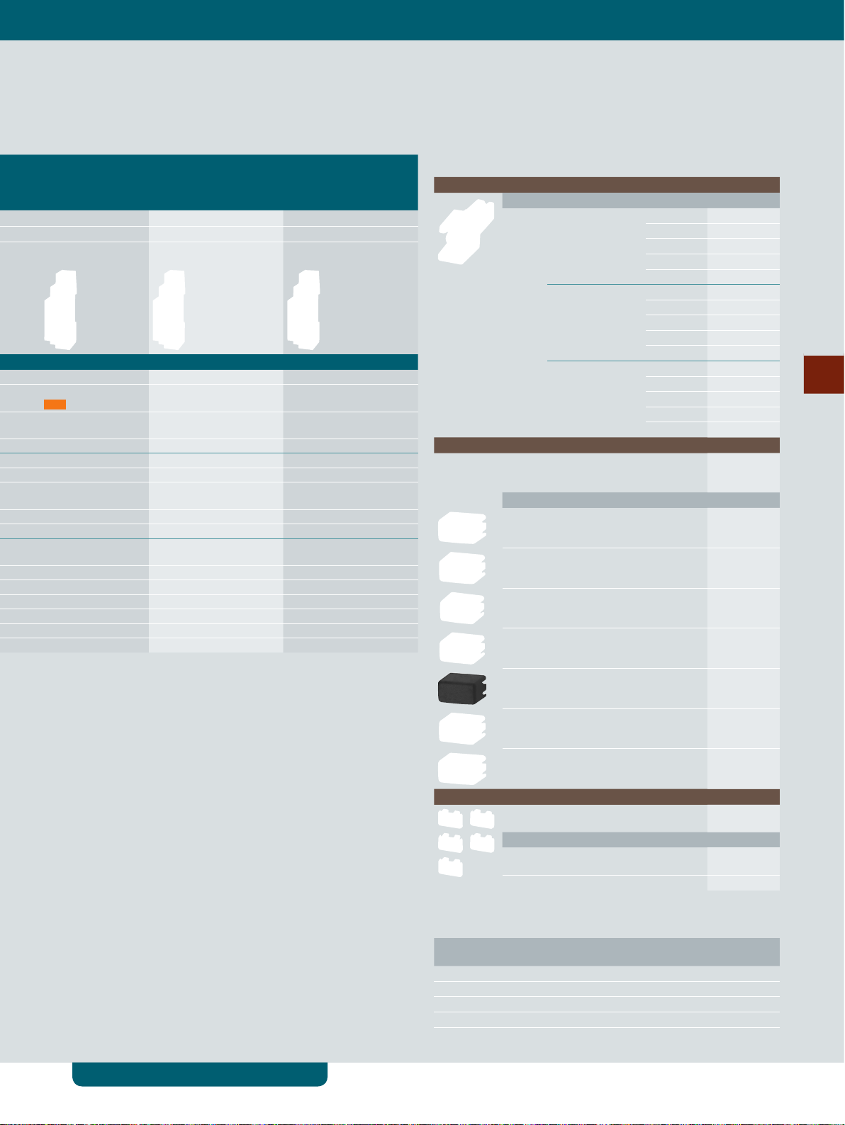
5TE81/82 On/Off switches
5TE81 On/Off switches 5TE82 On/Off switches
20 A 32 A
© Siemens 2020
Rated operational current I
per conducting path
Rigid conductor cross-section
Flexible conductor cross-section,
with end sleeve
Contacts Ue AC Mounting width Auxiliary switches Auxiliary switches
5
1 NO 230 V 1 MW 5TE8111 – – 5TE8211 – –
2 NO 400 V 1 MW 5TE8112 – – 5TE8212 – –
3 NO 400 V 1 MW 5TE8113 – – 5TE8213 – –
3 NO + N 400 V 1 MW – 5TE8114 – – 5TE8214 –
1.5 MW – – 5TE8118 – – 5TE8218
e
1.5 ... 6 mm
1 … 6 mm
Can be
retrotted
2
2
Cannot be
retrotted
1.5 ... 6 mm
1 … 6 mm
Mounted Can be
retrotted
2
2
Cannot be
retrotted
Mounted
Further technical specications 5TE81 5TE82
Standards
Standards IEC/EN 60947-3 (VDE 0660-107),
Approvals IEC/EN 60947-3 (VDE 0660-107)
Supply
Rated power dissipation P
Contacts
Minimum contact load 10 V; 300 mA
Rated making/rated breaking capacity At p.f. = 0.65 60 A / 60 A 96 A / 96 A
Rated short-time withstand current I
per conducting path at p.f. = 0.7
Thermal rated current I
Electrical/mechanical service life Actuations 10000 / 25000
Safety
Clearances Open contacts 2× >2 mm
Creepage distances >7 mm
Rated short-circuit making capacity I
Rated impulse withstand voltage U
Connections
Terminals ± Screw (Pozidriv) PZ 1
Environmental conditions
Permissible ambient temperature –5 … +40 °C
Resistance to climate at 95% relative humidity Acc. to DIN 50015 45 °C
v
cw
th
cm
imp
Per pole 0.7 VA
Up to 0.2 s 650 A 1000 A
Up to 0.5 s 400 A 630 A
Up to 1 s 290 A 450 A
Up to 3 s 170 A 250 A
Between the poles >7 mm
Max. tightening torque 1.2 Nm
IEC/EN 60669-1
20 A 32 A
10 kA
>5 kV
IEC/EN 60947-3 (VDE 0660-107)
5/12
Siemens LV 10 · 04/2020
System overview, page 5/4
Accessories
Auxiliary switches (AS)
Handle locking device
© Siemens 2020
Installation switching devices
• For right-hand-side retrotting with factory-tted brackets
Contacts Version Article No.
1 NO + 1 NC Standard 5ST3010
For low power 5ST3013
For low power (with diode) 5ST3013-0XX01
2 NO Standard 5ST3011
For low power 5ST3014
2 NC Standard 5ST3012
For low power 5ST3015
1 CO Standard 5ST3016
• To prevent undesired mechanical On/Off switching
• Sealable
• For padlock with max. 3 mm shackle
|
Switching Devices
Article No.
5ST3801
5
Terminal cover
Spacer
• For covering screw openings
• Sealable
Article No.
5ST3800
• Contour for modular devices with a mounting depth of 70 mm
• Can be snapped onto either side of the busbar for convenient cable routing
• Spacer is recommended for better heat dissipation
Article No.
5TG8240
System overview, page 5/4
Siemens LV 10 · 04/2020
5/13
 Loading...