

Siemens LOHER CHEMSTAR 1PS2 Operating Instructions And Installation
siemens.com
For employment in zone 1 or zone 2 (IEC/EN 60079-10-1)
0102
II 2G Ex e IIC T. Gb
LOHER CHEMSTAR
Induction motor
Type 1PS2
Operating Instructions / Installation Instructions N-R 601e
Edition 08/2016

04.08.2016 11:45
V3.00
LOHER CHEMSTAR
Induction motor
1PS2
For employment in zone 1 or zone 2 (IEC/EN
60079-10-1)
0102
II 2G Ex e IIC T. Gb
Introduction
1
Operating Instructions
Installation Instructions
Safety information
Description
Preparations for use
Assembly
Electrical connection
Start-up
Operation
2
3
4
5
6
7
8
Maintenance
Spare Parts
Disposal
Service and Support
Technical data and drawings
Quality documents
9
10
11
A
B
C
Edition 08/2016

Legal information
Warning notice system
This manual contains notices you have to observe in order to ensure your personal safety, as well as to prevent
damage to property. The notices referring to your personal safety are highlighted in the manual by a safety alert
symbol, notices referring only to property damage have no safety alert symbol. These notices shown below are
graded according to the degree of danger.
DANGER
indicates that death or severe personal injury will result if proper precautions are not taken.
WARNING
indicates that death or severe personal injury may result if proper precautions are not taken.
CAUTION
indicates that minor personal injury can result if proper precautions are not taken.
NOTICE
indicates that property damage can result if proper precautions are not taken.
If more than one degree of danger is present, the warning notice representing the highest degree of danger will be
used. A notice warning of injury to persons with a safety alert symbol may also include a warning relating to property
damage.
Qualified Personnel
The product/system described in this documentation may be operated only by personnel qualified for the specific
task in accordance with the relevant documentation, in particular its warning notices and safety instructions. Qualified
personnel are those who, based on their training and experience, are capable of identifying risks and avoiding
potential hazards when working with these products/systems.
Proper use of Siemens products
Note the following:
WARNING
Siemens products may only be used for the applications described in the catalog and in the relevant technical
documentation. If
products and components from other manufacturers are used, these must be recommended or
approved by Siemens. Proper transport, storage, installation, assembly, commissioning, operation and
maintenance are required to ensure that the products operate safely and without any problems. The permissible
ambient conditions must be complied with. The information in the relevant documentation must be observed.
Trademarks
All names identified by ® are registered trademarks of Siemens AG. The remaining trademarks in this publication
may be trademarks whose use by third parties for their own purposes could violate the rights of the owner.
Disclaimer of Liability
have
We
Since variance cannot be precluded entirely, we cannot guarantee full consistency. However, the information in
this publication is reviewed regularly and any necessary corrections are included in subsequent editions.
reviewed the contents of this publication to ensure consistency with the hardware and software described.
Siemens AG
Process Industries and Drives
Postfach 48 48
90026 NÜRNBERG
GERMANY
Document order number: N-R 601e
Ⓟ 08/2016 Subject to change
Copyright © Siemens AG 2016.
All rights reserved

Table of contents
1 Introduction.................................................................................................................................................11
1.1 About these instructions.........................................................................................................11
2 Safety information.......................................................................................................................................13
2.1 Information for those responsible for the plant.......................................................................13
2.2 The five safety rules...............................................................................................................14
2.3 Qualified personnel................................................................................................................14
2.4 Safe handling.........................................................................................................................14
2.5 Use in hazardous areas.........................................................................................................16
2.6 Electrostatic sensitive devices...............................................................................................17
2.7 Electromagnetic compatibility.................................................................................................18
2.8 Interference immunity.............................................................................................................18
2.9 Influence on the line power supply through a strongly irregular torque..................................19
2.10 Electromagnetic fields when operating electrical power engineering installations.................19
3 Description..................................................................................................................................................21
4 Preparations for use...................................................................................................................................25
4.1 Safety-related aspects to consider when configuring the plant..............................................25
4.2 Observing the operating mode...............................................................................................25
4.3 Terminal box with separate cable entry plate.........................................................................26
4.4 Machines without final paint coating......................................................................................27
4.5 Corrosion protection for bare metal surfaces.........................................................................27
4.6 Ensuring adequate cooling.....................................................................................................27
4.7 Interlock circuit for anti-condensation heating........................................................................28
4.8 Interlock circuit for the external fan motor..............................................................................28
4.9 Noise emissions.....................................................................................................................28
4.10 Voltage and frequency fluctuations during line operation......................................................29
4.11 System-inherent frequencies.................................................................................................30
4.12 Torsional loading of the shaft assembly due to faults in the electrical supply........................30
4.13 Transport and storage............................................................................................................30
4.13.1 Transport markings................................................................................................................31
4.13.2 Checking the delivery.............................................................................................................31
4.13.3 Attaching the rotor locking device..........................................................................................31
4.13.4 Checking the load handling attachments...............................................................................32
4.13.5 Storage for up to two years....................................................................................................33
LOHER CHEMSTAR 1PS2
Operating Instructions 08/2016 5

Table of contents
4.13.5.1 Storage conditions.................................................................................................................33
4.13.5.2 Commissioning.......................................................................................................................33
4.13.6 Storage for between two and four years................................................................................34
4.13.6.1 Grease caps...........................................................................................................................34
4.13.6.2 Commissioning.......................................................................................................................34
4.13.7 Storage at low temperatures..................................................................................................34
4.13.7.1 Storing machines at temperatures down to -50° C................................................................34
4.13.7.2 Regreasing system................................................................................................................34
4.13.8 Machines that are mounted together with the driven machine and transported....................35
4.13.8.1 Storing machines together with the driven machine..............................................................35
4.13.8.2 Commissioning.......................................................................................................................35
4.13.9 Storage outdoors....................................................................................................................35
4.13.10 Commissioning after storage.................................................................................................36
4.13.10.1 Insulation resistance and polarization index..........................................................................36
4.13.10.2 Lubricating the roller bearings ...............................................................................................36
4.13.10.3 Regreasing roller bearings after storage periods of up to two years......................................36
4.13.10.4 Regreasing roller bearings after storage periods of between two and four years..................37
4.13.10.5 Releasing the rotor shipping brace before commissioning....................................................37
5 Assembly....................................................................................................................................................39
5.1 Conformity..............................................................................................................................39
5.2 Modifications to the machine..................................................................................................39
5.3 Preparations for installation....................................................................................................40
5.3.1 Requirements for installation..................................................................................................40
5.3.2 Safety information – do not lift below -55°C...........................................................................40
5.3.3 Preparing the assembly area.................................................................................................41
5.3.4 Prepare the mating faces for wall mounting ..........................................................................41
5.4 Lift the machine to where it will be installed, and position it...................................................41
5.4.1 Preconditions for correct alignment and secure attachment .................................................41
5.4.2 Checking the load handling attachments...............................................................................42
5.4.3 Lifting and transportation........................................................................................................42
5.4.4 Putting the machine down......................................................................................................44
5.4.5 Turning a machine upright or laying it on its side...................................................................44
5.4.6 Removing anti-corrosion protection.......................................................................................45
5.4.7 Draining condensate..............................................................................................................47
5.5 Installing the machine............................................................................................................47
5.5.1 Preconditions for smooth, vibration-free operation................................................................47
5.5.2 Aligning the machine to the driven machine and mounting....................................................48
5.5.2.1 Selecting bolts........................................................................................................................48
5.5.2.2 Horizontal types of construction with mounting feet...............................................................48
5.5.2.3 Vertical types of construction with flange...............................................................................49
5.5.3 Removing the rotor shipping brace........................................................................................49
5.5.4 Recommended alignment accuracy.......................................................................................50
5.5.5 Mounting the output elements................................................................................................50
5.5.6 Axial and radial forces ...........................................................................................................52
6 Electrical connection...................................................................................................................................53
6.1 Preparation.............................................................................................................................54
6.1.1 Terminal box with cable entry plate........................................................................................54
6.1.2 Selecting cables.....................................................................................................................55
LOHER CHEMSTAR 1PS2
6 Operating Instructions 08/2016

Table of contents
6.2 Connecting.............................................................................................................................55
6.2.1 Terminal boxes with type of protection "Ex e" .......................................................................55
6.2.2 Connecting the grounding conductor.....................................................................................56
6.2.3 Circuit diagram in the terminal box cover...............................................................................56
6.2.4 Terminal designation..............................................................................................................57
6.2.5 Connecting the machine for a specific direction of rotation....................................................57
6.2.6 Terminal box..........................................................................................................................57
6.2.7 Minimum air clearances.........................................................................................................58
6.2.8 Cable ends with wire end sleeves..........................................................................................59
6.2.9 Connection with terminal board..............................................................................................59
6.2.10 Tightening torques for cable glands ......................................................................................60
6.2.11 Connecting aluminum conductors..........................................................................................61
6.2.12 O-ring seal .............................................................................................................................61
6.2.13 Finishing connection work......................................................................................................62
6.2.14 Internal equipotential bonding ...............................................................................................62
7 Start-up.......................................................................................................................................................65
7.1 Checks to be carried out prior to commissioning ..................................................................65
7.2 Insulation resistance and polarization index..........................................................................66
7.3 Testing the insulation resistance and polarization index........................................................67
7.4 Heating in order to reach the required surface temperature..................................................69
7.5 Testing the cooling of the machine........................................................................................70
7.6 Commissioning an external fan..............................................................................................70
7.7 Greasing the roller bearings prior to commissioning..............................................................71
7.8 Test run..................................................................................................................................72
8 Operation....................................................................................................................................................75
8.1 Safety instructions during operation.......................................................................................75
8.2 Current transformer................................................................................................................76
8.3 Explosion hazard during operation.........................................................................................77
8.4 Switching on with the anti-condensation heating active.........................................................77
8.5 Switching on the machine......................................................................................................78
8.6 Switching off the external fan ................................................................................................78
8.7 Switching on again after an emergency switching-off............................................................78
8.8 Stoppages..............................................................................................................................79
8.8.1 Switching on the anti-condensation heater............................................................................79
8.8.2 Avoidance of damage to roller bearings during stoppages....................................................80
8.9 Decommissioning the machine..............................................................................................80
8.10 Re-commissioning the machine.............................................................................................80
8.11 faults.......................................................................................................................................81
8.11.1 Inspections in the event of faults............................................................................................81
8.11.2 Electrical faults.......................................................................................................................81
8.11.3 Mechanical faults...................................................................................................................82
LOHER CHEMSTAR 1PS2
Operating Instructions 08/2016 7

Table of contents
8.11.4 Roller bearing faults...............................................................................................................82
8.11.5 Faults at the external fan........................................................................................................83
9 Maintenance...............................................................................................................................................85
9.1 Inspection and maintenance..................................................................................................85
9.1.1 Safety instructions for inspection and maintenance...............................................................85
9.1.2 Risk of explosion due to electrostatic charging......................................................................87
9.1.3 Inspections in the event of faults............................................................................................87
9.1.4 First inspection.......................................................................................................................87
9.1.5 General inspection.................................................................................................................88
9.1.6 Servicing the roller bearings...................................................................................................88
9.1.7 Maintenance...........................................................................................................................89
9.1.7.1 Insulation resistance and polarization index..........................................................................89
9.1.7.2 Grease stability times and mass of fillings.............................................................................90
9.1.7.3 Regreasing intervals and types of grease for operating rolling-contact bearings..................91
9.1.7.4 Alternative types of grease for the operation of roller bearings..............................................93
9.1.7.5 Cleaning the cooling air passages.........................................................................................94
9.1.7.6 Maintaining terminal boxes "Ex d"..........................................................................................95
9.1.7.7 Touch up any damaged paintwork.........................................................................................96
9.1.7.8 Repainting..............................................................................................................................96
9.2 Corrective Maintenance.........................................................................................................97
9.2.1 Assembling the rolling-contact bearings................................................................................98
9.2.2 Fixing stator cables at the terminal studs...............................................................................99
9.2.3 Seal the motor......................................................................................................................100
9.2.4 O-ring seal ...........................................................................................................................100
9.2.5 Anti-condensation heating spare parts.................................................................................101
10 Spare Parts...............................................................................................................................................103
10.1 Ordering data.......................................................................................................................103
10.2 Anti-condensation heating....................................................................................................104
10.3 Spare parts list, frame sizes 071 to 132...............................................................................105
10.4 Spare parts list, frame sizes 160 to 280...............................................................................106
10.5 Spare parts list, frame size 315............................................................................................108
10.6 Spare parts list, frame size 355............................................................................................109
10.7 Spare parts list for terminal boxes with type of protection "Ex e", frame sizes 071-160......111
10.8 Spare parts list for terminal boxes with type of protection "Ex e", frame sizes 180-225......112
10.9 Spare parts list for terminal boxes with type of protection "Ex e", frame sizes 250 to 355....113
10.10 Spare parts list for terminal boxes with type of protection "Ex i"..........................................114
11 Disposal....................................................................................................................................................115
11.1 RoHS - restricting the use of certain hazardous substances...............................................115
11.2 Dismantling the machine......................................................................................................115
11.3 Disposal of components.......................................................................................................116
LOHER CHEMSTAR 1PS2
8 Operating Instructions 08/2016

Table of contents
A Service and Support.................................................................................................................................117
B Technical data and drawings....................................................................................................................119
C Quality documents....................................................................................................................................121
C.1 EC Declaration of Conformity...............................................................................................121
C.2 IECEx certificate...................................................................................................................137
Index.........................................................................................................................................................139
Tables
Table 3-1 Marking of machines with type of protection Ex e.......................................................................21
Table 3-2 Machine design ..........................................................................................................................22
Table 3-3 Machine type with type of protection Ex e...................................................................................22
Table 5-1 Recommended alignment accuracy............................................................................................50
Table 5-2 Overall flatness of the installation surfaces.................................................................................50
Table 6-1 Determining the cross-section of the grounding conductor.........................................................56
Table 6-2 Terminal designations using the 1U1-1 as an example..............................................................57
Table 6-3 Minimum air clearance dependent on rms value of the alternating voltage U
.........................58
rms
Table 6-4 Tightening torques for standard cable glands [Nm] ................................................................60
Table 7-1 Stator winding insulation resistance at 40° C..............................................................................68
Table 8-1 Assignment of the total risk factor to the required supplementary measures for Ex e................77
Table 8-2 Electrical faults .......................................................................................................................81
Table 8-3 Mechanical faults .....................................................................................................................82
Table 8-4 Roller bearing faults ...............................................................................................................82
Table 8-5 Cooling system faults ...............................................................................................................83
Table 9-1 Checks after installation or repair ...............................................................................................87
Table 9-2 Checks that have to be performed during the general inspection...............................................88
Table B-1 Tightening torques for bolted connections with a tolerance of ±10%........................................119
Images
Image 4-1 Disassembly / assembly of terminal box.....................................................................................26
Image 5-1 Erecting the motor.......................................................................................................................45
Image 6-1 Disassembly / assembly of terminal box.....................................................................................54
Image 6-2 Example for conductor connection..............................................................................................59
Image 6-3 Example for conductor connection..............................................................................................60
Image 10-1 D-DN000-0007..........................................................................................................................105
Image 10-2 E-AN000-0004...........................................................................................................................106
Image 10-3 E-AN000-0005...........................................................................................................................108
Image 10-4 E-DN000-0010..........................................................................................................................109
LOHER CHEMSTAR 1PS2
Operating Instructions 08/2016 9

Table of contents
Image 10-5 E-9-101_162-0001.....................................................................................................................111
Image 10-6 E-9-101_208-0001.....................................................................................................................112
Image 10-7 E-9-101_285-0001.....................................................................................................................113
Image 10-8 Spare parts list for terminal boxes with type of protection "Ex i"...............................................114
LOHER CHEMSTAR 1PS2
10 Operating Instructions 08/2016

Introduction
1.1 About these instructions
These instructions describe the machine and explain how to handle it, from initial delivery to
final disposal of the equipment. Keep these instructions for later use.
Read these operating instructions before you handle the machine and follow the instructions
to become
machine operation and long service life.
Please contact the Service Center if you have any suggestions on how to improve this
document.
Text format features
The warning notice system is explained on the rear of the inside front. Always follow the safety
instructions and notices in these instructions.
In addition to the safety-related warning notices which you must read, you will find the text in
these instructions is formatted in the following way:
1. Handling instructions are always formatted as a numbered list. Always perform the steps
in the order given.
familiar with its design and operating principles and thus ensure safe, problem-free
1
● Lists are formatted as bulleted lists.
– Lists on the second level are hyphenated.
Note
A Note is an important item of information about the product, handling of the product or the
relevant section of the document. Notes provide you with help or further suggestions/ideas.
LOHER CHEMSTAR 1PS2
Operating Instructions 08/2016 11

Introduction
1.1 About these instructions
LOHER CHEMSTAR 1PS2
12 Operating Instructions 08/2016

Safety information
2.1 Information for those responsible for the plant
This electric machine has been designed and built in accordance with the specifications
contained in Directive 2014/35/EU ("Low-Voltage Directive") and is intended for use in
industrial plants. Please observe the country-specific regulations when using the electric
machine outside the European Community. Follow the local and industry-specific safety and
setup regulations.
The persons responsible for the plant must ensure the following:
● Planning and configuration work and all work carried out on and with the machine is only
to be done by qualified personnel.
The operating instructions must always be available for all work.
●
● The technical data as well as the specifications relating to the permissible installation,
connection, ambient and operating conditions are taken into account at all times.
● The specific setup and safety regulations as well as regulations on the use of personal
protective equipment are observed.
Note
Use the services and support provided by the appropriate Service Center for planning,
installation, commissioning, and servicing work.
2
You will find safety instructions in the individual sections of this document. Follow the safety
instructions for your own safety, to protect other people and to avoid damage to property.
Observe the following safety instructions for all activities on and with the machine.
This machine has been designed and built in accordance with Directive 2014/34/EU
("Explosion Protection Directive") and is intended for use in industrial plants with potentially
explosive atmosphere.
Commissioning in the European Community in accordance with Directive 2006/42/EU
(“Machinery Directive”)
been shown to conform with this directive. Please observe the country-specific regulations
when using the machine outside the European Community.
WARNING
Risk of explosion with commissioning prior to determining the conformity
If the machine is commissioned prior to determining the plant conformance, the explosion
of
protection
injury or material damage.
Do not commission the machine until it has been confirmed that the plant conforms with the
explosion protection directive.
the plant is not ensured. An explosion can occur. This can result in death, serious
is forbidden until the plant into which the machine will be installed has
LOHER CHEMSTAR 1PS2
Operating Instructions 08/2016 13

Safety information
2.4 Safe handling
2.2 The five safety rules
For your own personal safety and to prevent material damage when carrying out any work,
always observe the safety-relevant instructions and the following five safety rules according
to EN 50110‑1 "Working in a voltage-free state". Apply the five safety rules in the sequence
stated before starting work.
Five safety rules
1. Disconnect the system.
Also disconnect the auxiliary circuits, for example, anti-condensation heating.
2. Secure against reconnection.
3. Verify absence of operating voltage.
4. Ground and short-circuit.
5. Provide protection against adjacent live parts.
To energize the system, apply the measures in reverse order.
2.3 Qualified personnel
All work at the machine must be carried out by qualified personnel only. For the purpose of
this documentation, qualified personnel is taken to mean people who fulfill the following
requirements:
● Through appropriate training and experience, they are able to recognize and avoid risks
and potential dangers in their particular field of activity.
● They have been instructed to carry out work on the machine by the appropriate person
responsible.
2.4 Safe handling
Workplace safety depends on the attentiveness, care, and common sense of the personnel
who install, operate, and maintain the machine. In addition to the safety measures cited, as a
matter of principle, the use of caution is necessary when you are near the machine. Always
pay attention to your safety.
Also observe the following to prevent accidents:
● General safety regulations applicable in the country where the machine is deployed.
● Manufacturer-specific and application-specific regulations
● Special agreements made with the operator
● Separate safety instructions supplied with the machine
● Safety symbols and instructions on the machine and its packaging
LOHER CHEMSTAR 1PS2
14 Operating Instructions 08/2016

Safety information
2.4 Safe handling
WARNING
Live parts
Electric machines contain live parts.
or
Fatal
severe injuries and substantial material damage can occur if the covers are removed
or if the machine is not handled, operated, or maintained properly.
● Always observe the “five safety rules" when carrying out any work on the machine.
● Only remove the covers using the methods described by these operating instructions.
● Operate the machine properly.
● Regularly and correctly maintain the machine.
WARNING
Rotating parts
Electric machines contain dangerous rotating parts.
Fatal or
severe injuries and substantial material damage can occur if the covers are removed
or if the machine is not handled, operated, or maintained properly.
● Only remove the covers using the methods described by these operating instructions.
● Operate the machine properly.
● Regularly and correctly maintain the machine.
● Secure free-standing shaft ends and other rotating parts such as couplings, belt pulleys
etc. against touch.
WARNING
Hot surfaces
Electric machines have hot surfaces. Do not touch these surfaces. They could cause burns.
● Allow the machine to cool before starting work on the machine.
Only remove the covers using the methods described by these operating instructions.
●
● Operate the machine properly.
CAUTION
Hazardous substances
Chemical substances required for the setup, operation and maintenance of machines can
present a health risk.
skin
Poisoning,
damage, cauterization of the respiratory tract, and other health damage may
result.
● Read the information in these operating instructions and the product information supplied
by the manufacturer.
● Observe the relevant safety regulations and wear the personal protective equipment
specified.
LOHER CHEMSTAR 1PS2
Operating Instructions 08/2016 15

Safety information
2.5 Use in hazardous areas
CAUTION
Flammable substances
Chemical substances required for the setup, operation and maintenance of machines may
be flammable.
Burns and other damage to health and material may result.
● Read the
by the manufacturer.
● Observe the relevant safety regulations and wear the personal protective equipment
specified.
See also
The five safety rules (Page 14)
WARNING
Noise emissions
information in these operating instructions and the product information supplied
During operation, the machine's noise emission levels can exceed those permitted at the
workplace, which can cause hearing damage.
steps to reduce noise, such as introducing covers and protective insulation or adopting
Take
hearing protection measures, so that the machine can be operated safely within your system.
2.5 Use in hazardous areas
Electrical systems in hazardous zones must be assembled, installed, and operated by the
applicable responsible persons in accordance with the applicable rules and regulations.
Note
The basic requirements relating to electrical systems and their operation in hazardous areas
are described, for instance, in EU Directive 1999/92/EC as well as in IEC / EN 60079-14.
LOHER CHEMSTAR 1PS2
16 Operating Instructions 08/2016

Ignition hazards
Safety information
2.6 Electrostatic sensitive devices
The assessment of operating risks and local operating conditions and the necessary
monitoring methods
with the responsible supervisory authority. The required measures must be adhered to at all
times. The machine manufacturer cannot provide any generally applicable recommendations.
Please observe the information in these operating instructions.
Note
The basic requirements relating to the assessment of ignition hazards arising from electrical
equipment and their operation in hazardous zones are specified in the 2014/34/EU and
1999/92/EC directives as well as in the IEC/EN 60079 series of standards.
If a third-party certification is available for the machine, then carefully comply with the technical
data defined in it and any special conditions.
The certificate must be available before commissioning.
must be clarified and made binding by the system operator in consultation
2.6 Electrostatic sensitive devices
ESD protective measures
NOTICE
Electrostatic discharge
Electronic modules contain components that can be destroyed by electrostatic discharge.
These modules can be easily destroyed by improper handling.
To protect equipment against damage, follow the instructions given below.
● Only touch electronic modules if you absolutely have to work on them.
The body of the person concerned must have been electrostatically discharged and
●
grounded immediately before any electronic modules are touched.
● Electronic modules should not be brought into contact with electrically insulating materials,
such as:
– Plastic film
– Plastic parts
– Insulating table supports
– Clothing made of synthetic fibers
● Always place electrostatic sensitive devices on conductive bases.
● Always pack, store and transport electronic modules or components in conductive
packaging, such as:
– Metallized plastic or metal containers
– Conductive foam material
– Domestic aluminum foil
LOHER CHEMSTAR 1PS2
Operating Instructions 08/2016 17

Safety information
2.8 Interference immunity
The necessary ESD protective measures for electrostatic sensitive devices are illustrated once
again in the following drawings:
(1) Sitting (2) Standing (3) Standing/sitting
a = conductive floor surface b = ESD table c = ESD shoes
d = ESD overall e = ESD wristband f = cabinet ground connection
WARNING
Risk of explosion due to electrostatic discharge
Electrostatic discharge poses a potential ignition source. Dangerous electrostatic charges
can occur, for example as a result of mechanical friction, flowing air that contains particles or persons that are not appropriately grounded, e.g. when carrying out maintenance or
cleaning work.
an
explosive atmosphere, there is a risk of an explosion. This can result in death, serious
In
injury or material damage.
● Avoid carrying out work specified above on non-metallic parts, e.g. foam rubber for noise
dampeners/attenuators.
● Please comply with ESD protective measures.
2.7 Electromagnetic compatibility
This machine
satisfies the requirements of European Directive 2014/30/EU on Electromagnetic Compatibility.
is designed in accordance with IEC/EN 60034, and when used as prescribed it
2.8 Interference immunity
The machine fulfills the requirements regarding interference immunity in conformity with IEC/
EN 61000‑6‑2.
On machines with integrated sensors (e.g. PTC thermistors), the manufacturer of the overall
system must himself ensure sufficient interference immunity by selecting suitable sensor signal
leads and evaluation units.
LOHER CHEMSTAR 1PS2
18 Operating Instructions 08/2016
Safety information
2.10 Electromagnetic fields when operating electrical power engineering installations
2.9 Influence on the line power supply through a strongly irregular torque
A strongly irregular torque, for example with the drive of a reciprocating motor, forces a nonsinusoidal motor current. The emerging harmonics can have an impermissible influence on
the line power supply via the connection lines.
2.10 Electromagnetic fields when operating electrical power engineering
installations
WARNING
Interference to electronic devices caused by electrical power equipment
Electrical power equipment generate electric fields during operation. Potentially lethal
can
malfunctions
equipment. Data may be lost on magnetic or electronic data carriers.
● It is forbidden for people with pacemakers to enter the vicinity of the machine.
● Protect the personnel working in the plant by taking appropriate measures, such as
erecting identifying markings, safety barriers and warning signs and giving safety talks.
● Observe the nationally applicable health and safety regulations.
● Do not carry any magnetic or electronic data media.
occur in medical implants, e.g. pacemakers, in the vicinity of electrical power
LOHER CHEMSTAR 1PS2
Operating Instructions 08/2016 19

Safety information
2.10 Electromagnetic fields when operating electrical power engineering installations
LOHER CHEMSTAR 1PS2
20 Operating Instructions 08/2016

Description
0102
0102
0102
0102
Applications
This electrical machine is designed for driving rotating machines in industrial environments
and also for energy conversion. It is characterized by a high level of safety, long lifetime, and
overall reliability.
The machine was designed in accordance with the ordering party's specification and may only
be used for the contractually agreed purpose.
Type of protection Ex e
This machine has "increased safety" (Ex e) type of protection according to IEC / EN 60079-7.
It can therefore be operated in hazardous areas of Zones 1 and 2 according to
IEC / EN 60079-10-1.
Use in hazardous areas
Explosion-proof electrical machines correspond to standards of the IEC/EN 60034 and IEC/
EN 60079 series. Only operate the machine in hazardous areas, strictly complying with the
specifications of the responsible supervisory authority. The relevant supervisory authority is
responsible for determining the hazard level of each area and classifying the zones. The type
of protection as well as special regulations are stamped on the rating plate or in the test
certificate. If the certificate number is supplemented by an X, to safely operate the machine
observe the special notes in the operating instructions or if available in the EC or EU typeexamination certificate or in the IECEx Certificate of Conformity. Operation with a converter
must be certified. It is essential that you observe the separate manufacturer's information and
instructions.
3
Machines with type of protection Ex e can have the following Ex marking:
Table 3-1 Marking of machines with type of protection Ex e
Directive Ex marking
2014/34/EU with EC or EU type-examina‐
tion certificate
IECEx scheme with Certificate of Con‐
formity
LOHER CHEMSTAR 1PS2
Operating Instructions 08/2016 21
Ex e IIC T1 to T4 Gb
Ex e d IIC T1 to T4 Gb
Ex e ib IIC T1 to T4 Gb
Ex e d ib IIC T1 to T4 Gb
II 2G Ex e IIC T1 to T4 Gb
II 2G Ex e d IIC T1 to T4 Gb
II 2G Ex e ib IIC T1 to T4 Gb
II 2G Ex e d ib IIC T1 to T4 Gb
Description
Machine design
See also
The regulations
and standards used as the basis to design and test this machine are stamped
on the rating plate.
The machine design basically complies with the subsequent standards. Please refer to the EC
or EU Declarations of Conformity for the versions of the harmonized standards referenced.
Table 3-2 Machine design
Feature Standard
Rating and performance IEC/EN 60034‑1
Degree of protection IEC/EN 60034‑5
Cooling IEC/EN 60034‑6
Type of construction IEC/EN 60034‑7
Terminal markings and direction of rotation IEC/EN 60034‑8
Noise emission IEC/EN 60034‑9
Starting characteristics, rotating electrical machines IEC/EN 60034‑12*
Vibration severity grades IEC/EN 60034‑14
Vibration limits DIN ISO 10816-3
* For machines in line operation only
Rating plate
Rotor
Quality documents (Page 121
)
The following standards additionally apply for explosion-protected machines:
Table 3-3 Machine type with type of protection Ex e
Characteristic Standard
Type of protection Ex e IEC / EN 60079‑0
IEC / EN 60079‑7
The rating
plate shows the identification data and the most important technical data. The data
on the rating plate and the contractual agreements define the limits of proper usage.
The rotor has a squirrel cage rotor manufactured out of die-cast aluminum or a brazed copper
rotor. The rotor is dynamically balanced with half feather key as standard. With a different
balancing status the marking for the corresponding balancing status is made using an adhesive
sticker.
LOHER CHEMSTAR 1PS2
22 Operating Instructions 08/2016

Stator winding
The stator winding has a temperature class according to EN 60034-1, see rating plate. Highquality enameled wires, suitable surface insulating materials, and the type of impregnation
guarantee great
service life.
Risk of ignition on the rotor
Note that the manufacturer has performed a risk assessment for all machines with regard to
sparking between the rotor and the stator. There is a risk of explosion if potentially explosive
gas is drawn in at startup. If purging is required, an additional plate must be attached to the
electric machine.
Additional plate:
Purging is required before the start in compliance with the risk evaluation for squirrel-cage
rotors according to IEC / EN 60079–15:2010
Refer to "Purging before the start"
Description
mechanical and electrical stability together with a high utility value and a long
Machine housing with surface, hollow-rib or tube cooling
Depending on their size, the stator frame and bearing shields are made of cast iron or steel.
The fan cover is made of sheet steel. The stator frame surface has cooling ribs, hollow ribs,
or tubes and mounted terminal box.
Cooling for machines with surface cooling, hollow-rib cooling or tube cooling
For machines with rib, hollow-rib or tube cooling, the cooling air is drawn in through openings
in the fan cover. The air is blown over the surface or through the cooling tubes of the stator
frame. With hollow-rib or tube cooling, a closed cooling air circuit inside the machine assists
with heat dissipation.
Bearings
The machine is equipped with grease-lubricated roller bearings.
● The bearings of the standard size machines (up to size 280) are permanently lubricated.
● The bearings of machines from size 315 upwards have a relubrication facility and automatic
grease quantity control.
Terminal boxes
In the terminal box, additional connecting terminals are available if required for monitoring
equipment. For larger machines, an additional terminal box can be optionally mounted. You
can see the number of available terminals in the circuit diagrams.
LOHER CHEMSTAR 1PS2
Operating Instructions 08/2016 23

Description
Paint finish
The machine is painted according to the instructions in your order.
Suitability test of the paint system for hazardous areas
Proof is available for the electrostatic suitability with explosion-proof machines for the paint
systems ordered by default. Such evidence is not available for paint systems that are nonstandard or specifically requested by customers. Take into consideration that the provided
evidence is not valid for repaintings.
Supplementary devices
Depending on the order, various supplementary devices can be installed or mounted. These
include sensors for bearing temperature monitoring or winding monitoring, for example.
Monitoring equipment
Monitoring equipment
semiconductor sensors are electrostatic sensitive devices (ESD). These elements can be
damaged by electrostatic discharge. Observe the ESD protective measures.
is provided corresponding to what has been ordered. KTY83 and KTY84
External fan
The machine can be fitted with an external fan. For IC 666, there are two external fans. The
electrical connection data are stamped on the rating plate of the external fan.
Anti-condensation heating
The machine can be fitted with anti-condensation heating. The connection data is listed on an
additional plate on the machine.
Float switches and damp location electrode
The machine can be fitted with float switches and/or damp location electrodes.
See also
Electrical connection (Page 53)
LOHER CHEMSTAR 1PS2
24 Operating Instructions 08/2016

Preparations for use
Good planning and preparation of machine applications are essential in terms of keeping
installation simple and avoiding errors, ensuring safe operation, and allowing access to the
machine for servicing and corrective maintenance.
4
This chapter
machine and the preparations you need to make before the machine is delivered.
outlines what you need to consider when configuring your plant in relation to this
4.1 Safety-related aspects to consider when configuring the plant
A number of residual risks are associated with the machine. These are described in the chapter
titled "Safety information" (Page 13) and in related sections.
Take appropriate safety precautions (covers, barriers, markings, etc.) to ensure the machine
is operated safely within your plant.
Observing the operating mode
Observe the machine's operating mode. Use a suitable control system to prevent overspeeds,
thus protecting the machine from damage.
4.2 Observing the operating mode
Observe the machine's operating mode. Use a suitable control system to prevent overspeeds,
thus protecting the machine from damage.
LOHER CHEMSTAR 1PS2
Operating Instructions 08/2016 25
Preparations for use
4.3 Terminal box with separate cable entry plate
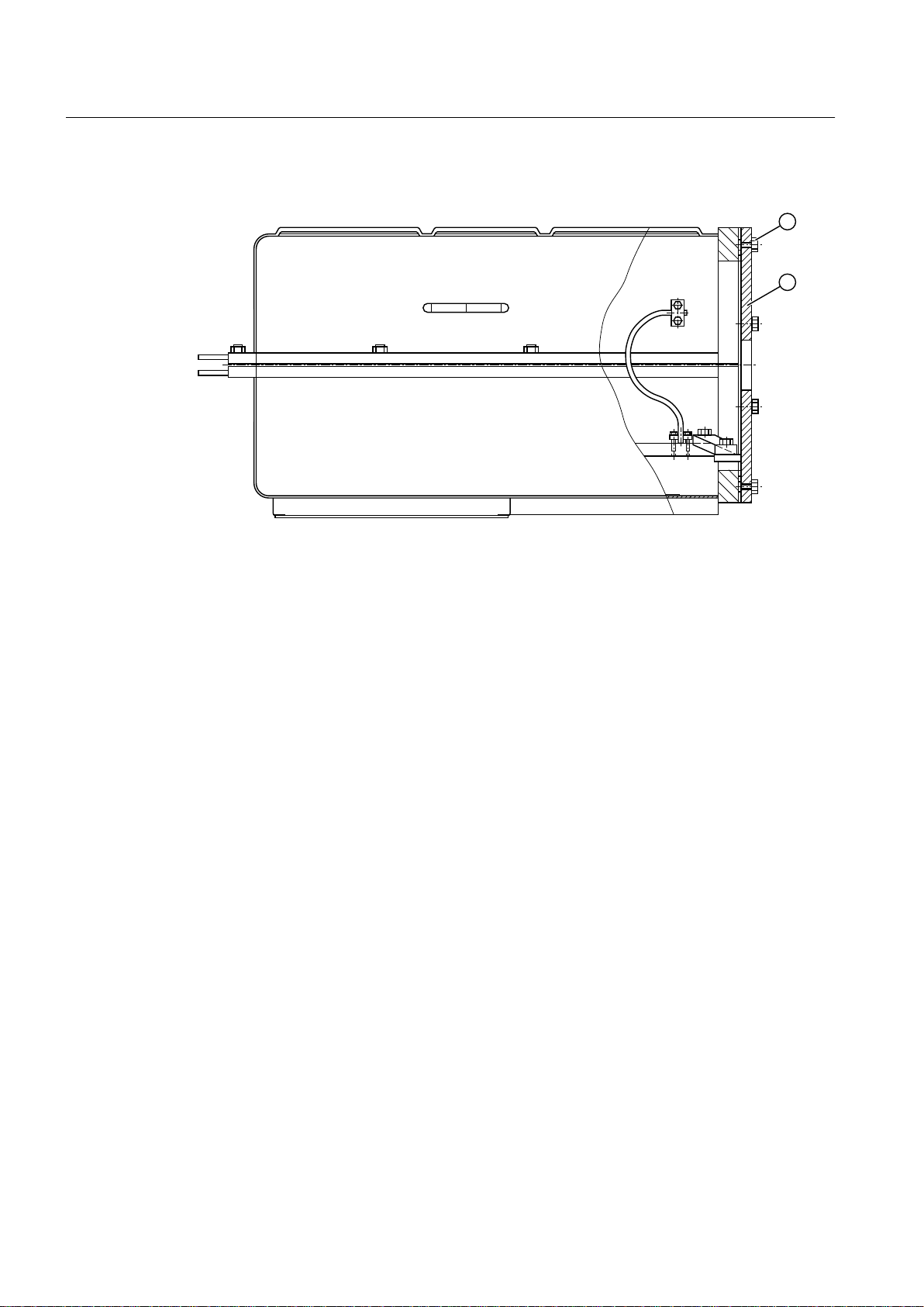
4.3 Terminal box with separate cable entry plate
Image 4-1 Disassembly / assembly of terminal box
Opening the terminal box:
1. Unscrew the
fixing screws ① and remove the ① cable entry plate ①. If present, unscrew
the cable entry plate ① grounding strap from the terminal box base.
2. To protect the seals, position the cable entry plate ① a short distance away from the
terminal box.
3. Unscrew the terminal box cover fixing screws ① and open the cover. For versions without
hinges, lift the cover of the terminal box off.
Electrical connection and final assembly:
1. Screw the cable gland(s) into the cable entry plate ② and push the cable entry plate ②
onto the connecting cables. Connect the cables to the terminals in accordance with all
applicable guidelines.
2. To protect the seals, position the cable entry plate ② a short distance away from the
terminal box. Then, if required, connect the grounding strap to the cable entry plate ②.
3. After making the electrical connections, close the cover of the terminal box. For versions
without hinges, place the terminal box cover onto the terminal box base. The seal between
the terminal box base and cover must be flush with the cable entry plate in order to ensure
the required degree of protection.
4. Carefully push the cable entry plate ② toward the terminal box. Screw the terminal box
base and cover together with the fixing screws ①. The terminal box base and cover must
both be in contact with the cable entry plate ② to ensure the required degree of protection.
5. Screw the terminal box cover on. Ensure that the terminal box seals are intact and
undamaged.
LOHER CHEMSTAR 1PS2
26 Operating Instructions 08/2016

DANGER
Danger due to damaged seals
Damaged seals can result in the failure of the explosion protection.
This can cause faults which can result in eventual or immediate death, serious injury or
material damage.
Only operate the machine with intact, undamaged seals.
4.4 Machines without final paint coating
For machines, which are only delivered with primer, you must paint them to comply with the
applicable guidelines
corrosion protection.
The paint applied must conform to the requirements to avoid electrostatic charging, see
EN 60079-0.
for the specific application. The primer alone does not provide adequate
Preparations for use
4.6 Ensuring adequate cooling
Note
Please contact the Service Center for recommendations relating to the paint finish.
4.5 Corrosion protection for bare metal surfaces
The lower side of the machine mounting feet or the flange surface is bare metal. Ensure that
there is adequate corrosion protection, e.g. using grease, sealing paste or a similar product.
The terminal box cover also has bare metal surfaces. Here, only use a suitable grease to
guarantee protection against corrosion.
4.6 Ensuring adequate cooling
Ensure that the machine is sufficiently cooled by the cooling air flow at the installation site:
Ensure that the cooling air can flow in and out unobstructed. The full air flow provided by
●
the fan is only possible if air can freely enter the impeller. In the axial direction, ensure a
clearance of at least 1 x air intake diameter.
● Make sure that the machine does not draw in the hot discharged air again.
● For machines with a vertical type construction with an air intake from above, ensure that
the air inlets are protected against the ingress of foreign bodies and water.
LOHER CHEMSTAR 1PS2
Operating Instructions 08/2016 27
Preparations for use
4.9 Noise emissions
4.7 Interlock circuit for anti-condensation heating
If the anti-condensation heating is operated while the machine is running, this can increase
the temperatures inside the machine.
● Install an interlock circuit that switches off the anti-condensation heating once the main
machine is switched on.
● Only switch on the anti-condensation heating after the motor has been switched off.
Carefully comply with the data on the anti-condensation heating plate.
See also
Switching on with the anti-condensation heating active (Page 77)
4.8 Interlock circuit for the external fan motor
Interlock circuit for the external fan motor
For machines with external fans, install an interlock circuit that prevents the main machine
being switched on if the external fan is not operational.
4.9 Noise emissions
WARNING
Noise emissions
During operation, the machine's noise emission levels can exceed those permitted at the
workplace, which can cause hearing damage.
Take
steps to reduce noise, such as introducing covers and protective insulation or adopting
hearing protection measures, so that the machine can be operated safely within your system.
LOHER CHEMSTAR 1PS2
28 Operating Instructions 08/2016

Preparations for use
4.10 Voltage and frequency fluctuations during line operation
4.10 Voltage and frequency fluctuations during line operation
The ranges stated on the rating plate and in the documentation (e.g. range B acc. to
IEC / EN 60034 1) for voltage fluctuation (± 10%) and frequency fluctuation (± 2 %) must be
maintained at all times.
The following always applies: Under practical operating conditions, a machine may sometimes
have to be operated outside the tolerance limits. Exceptions of this sort should be limited with
regard to the values that arise, how often and for how long they occur. Where possible and
within a reasonable time take corrective actions such as reducing the power. Such actions can
avoid thermal ageing leading to a reduction in the service life of the machine.
NOTICE
Overheating of the winding
Exceeding the
high temperature rise in the windings and thus cause long-term damage to the machine.
Every machine must be protected against an inadmissible temperature rise. Observe the
following notes:
● Protect every
circuit breaker with phase failure protection according to IEC/EN 60947 or a similar device
in all phases.
● Set the protective device to the rated current (value is stamped on the rating plate).
● Select the protective device so that the machine is thermally protected even with a locked
rotor.
● For explosion-protected electrical machines with type of protection "Increased safety", also
monitor the starting (starting monitoring with EC or EU type-examination certificate
according to Directive 2014/34/EU or IECEx scheme with Certificate of Conformity). When
the rotor is locked, the protective device must trip within the tE time (safe locked rotor time).
This requirement is satisfied if the tripping time is not longer than the specified tE time.
● Protect the windings in a delta connection in such a way that the tripping unit or relay is
connected in series with the winding phases. When selecting and setting the tripping unit,
define the rated value of the phase current. The phase current is 0.58 times the rated
machine current. Any thermal machine protection via direct temperature monitoring to be
used in addition to the machine circuit breaker is specified on the rating plate if required.
permissible tolerances for voltage and frequency can lead to an impermissibly
machine according to IEC/EN 60079–14 using a current-dependent, delayed
LOHER CHEMSTAR 1PS2
Operating Instructions 08/2016 29

Preparations for use
4.13 Transport and storage
4.11 System-inherent frequencies
NOTICE
System resonances
Excessive vibrations and system resonances can damage the machine set.
Configure and match the system consisting of the foundation and machine set in such a
●
way that no system resonances can arise and result in the permissible vibration levels
being exceeded.
●
The vibration limit values according to DIN ISO 10816-3 must not be exceeded.
4.12 Torsional loading of the shaft assembly due to faults in the electrical supply
In the event of faults in the electrical supply, such as e.g. line switching operations with a
residual field or short circuit at the terminals, excessive air gap torques can occur, which can
lead to additional torsional loads on the drive train.
See also
4.13
WARNING
Serious damage to the machine
the
configuration does not correctly recognize the mechanical torsional loadings of the shaft
If
assembly, this can lead to serious damage to the machine. This can result in death, serious
injury or material damage.
When planning the system, make due allowance for the maximum air gap torques that can
occur. This data can be found in the "Electrical Data" in the appendix, in the "Transient
Torques" data sheet, or by inquiring at the Service Center.
Note
The system planner is responsible for the complete shaft train.
Technical data and drawings (Page 119)
Transport and storage
When carrying out any work on the machine, observe the general safety instructions and the
specifications contained in EN 50110‑1 regarding safe operation of electrical equipment.
LOHER CHEMSTAR 1PS2
30 Operating Instructions 08/2016
 Loading...