

Siemens LOGO! CMR2040, LOGO! CMR2020 Operating Instructions Manual

___________________
___________________
___________________
___________________
___________________
___________________
___________________
___________________
___________________
___________________
___________________
___________________
___________________
SIMATIC NET
LOGO! - Industrial Ethernet
LOGO! CMR2020,
LOGO! CMR2040
Operating Instructions
10/2016
C79000
Preface
Application and functions
1
LEDs, connectors, buttons,
card slots
2
Installation, connecting up,
commissioning
3
Operation: Access to BM
4
Configuration (WBM)
5
Diagnostics and
maintenance
6
Dimension drawings
7
Technical specifications
8
Approvals
9
Accessories
A
Additional information on
SMS
B
Documentation references
C
-G8976-C356-03
Siemens AG
Division Process Industries and Drives
Postfach 48 48
90026 NÜRNBERG
GERMANY
C79000-G8976-C356-03
Ⓟ
Copyright © Siemens AG 2014 - 2016.
All rights reserved
Legal information
Warning notice system
DANGER
indicates that death or severe personal injury will result if proper precautions are not taken.
WARNING
indicates that death or severe personal injury may result if proper precautions are not taken.
CAUTION
indicates that minor personal injury can result if proper precautions are not taken.
NOTICE
indicates that property damage can result if proper precautions are not taken.
Qualified Personnel
personnel qualified
Proper use of Siemens products
WARNING
Siemens products may only be used for the applications described in the catalog and in the relevant technical
maintenance are required to ensure that the products operate safely and without any problems. The permissible
ambient conditions must be complied with. The information in the relevant documentation must be observed.
Trademarks
Disclaimer of Liability
This manual contains notices you have to observe in order to ensure your personal safety, as well as to prevent
damage to property. The notices referring to your personal safety are highlighted in the manual by a safety alert
symbol, notices referring only to property damage have no safety alert symbol. These notices shown below are
graded according to the degree of danger.
If more than one degree of danger is present, the warning notice representing the highest degree of danger will
be used. A notice warning of injury to persons with a safety alert symbol may also include a warning relating to
property damage.
The product/system described in this documentation may be operated only by
task in accordance with the relevant documentation, in particular its warning notices and safety instructions.
Qualified personnel are those who, based on their training and experience, are capable of identifying risks and
avoiding potential hazards when working with these products/systems.
Note the following:
documentation. If products and components from other manufacturers are used, these must be recommended
or approved by Siemens. Proper transport, storage, installation, assembly, commissioning, operation and
All names identified by ® are registered trademarks of Siemens AG. The remaining trademarks in this publication
may be trademarks whose use by third parties for their own purposes could violate the rights of the owner.
We have reviewed the contents of this publication to ensure consistency with the hardware and software
described. Since variance cannot be precluded entirely, we cannot guarantee full consistency. However, the
information in this publication is reviewed regularly and any necessary corrections are included in subsequent
editions.
for the specific
11/2016 Subject to change
Preface
Validity of this manual
This document contains information on the following LOGO! products:
● LOGO! CMR2020
Hardware product version: 1
Firmware version: V2.0
Article number: 6GK7 142-7BX00-0AX0
Communications module for connection of LOGO! 8 to the GSM/GPRS network (2G)
● LOGO! CMR2040
Hardware product version: 1
Firmware version: V2.0
Article number: 6GK7 142-7EX00-0AX0
Communications module for connection of LOGO! 8 to the LTE network (4G)
LOGO! CMR2020, LOGO! CMR2040
Operating Instructions, 10/2016, C79000-G8976-C356-03
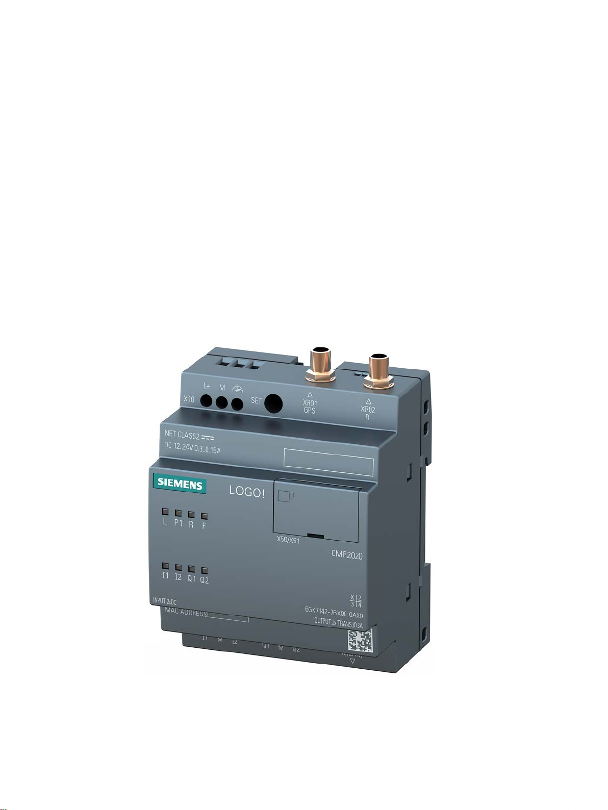
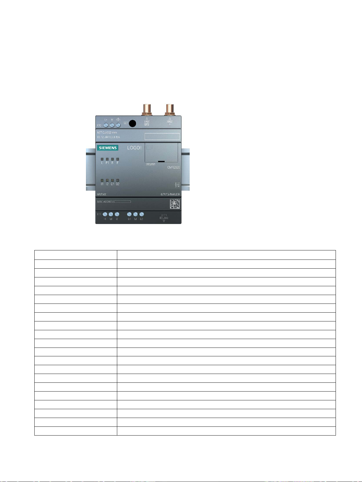
Figure 1 LOGO! CMR2020
The two devices differ in the supported mobile wireless standards. The remaining range of
functions of both devices is identical.
3

Preface
Product names and abbreviations
Purpose of the manual
New in this release
Replaced documentation
Current manual release on the Internet
● CMR or device
In this document, the term "CMR" or "device" is also used instead of the full product name
"LOGO! CMR2020 or LOGO! CMR2040. CMR is the abbreviation for Communication
Module Radio.
● BM or LOGO! BM
Basic module: LOGO! 8
● WBM
Web Based Management; Web user interface with which the CMR is configured.
● SD card
Below, the term “SD card" is used instead of micro SD card.
This manual supports you during the configuration, installation, commissioning and operation
of the communications modules LOGO! CMR2020 and LOGO! CMR2040.
A detailed example (Page 121) supports you during commissioning.
● New functions of the above firmware version:
– OpenVPN for transfer via glass mobile wireless
– HTTPS via LAN and mobile wireless
– Simplified syntax for writing and reading SMS messages
– Sending e-mails
– DynDNS for the mobile wireless interface (only with public IP address)
● Further national approvals, see section Approvals (Page 145).
● Editorial revision, see also section System Time (Page 72).
This manual replaces the manual edition 05/2015.
You will also find the current version of this manual on the Internet pages of Siemens
Industry Online Support at the following address:
Link: (https://support.industry.siemens.com/cs/ww/en/view/109477418)
LOGO! CMR2020, LOGO! CMR2040
4 Operating Instructions, 10/2016, C79000-G8976-C356-03
Preface
Cross references
Sources of information and other documentation
Use of the device
WARNING
Impairment of medical devices and data media
License conditions
Note
Open source software
Read the license conditions for open source software carefully before using the product.
Security information
In this manual there are often cross references to other sections.
To be able to return to the initial page after jumping to a cross reference, some PDF readers
support the command <Alt>+<left arrow>.
You will find an overview of further reading and references in the Documentation references
in this manual.
Connection of a LOGO! BM to an LTE, UMTS or GSM/GPRS mobile wireless network and a
GPS system.
The device contains a wireless transmitter that could, under certain circumstances, impair
the functionality of electronic medical devices such as hearing aids or pacemakers. Do not
use the device in places where the operation of wireless devices is prohibited. You can
obtain advice from your physician or the manufacturer of such devices.
To prevent data media from being demagnetized, do not keep disks, credit cards or other
magnetic data media near the device.
The license conditions for open source software are stored on the device and can be read
out using the WBM: In the header line of the WBM you will find an icon with you can save the
OSS license texts on the PC and then extract and open them.
Siemens provides products and solutions with industrial security functions that support the
secure operation of plants, systems, machines and networks.
In order to protect plants, systems, machines and networks against cyber threats, it is
necessary to implement – and continuously maintain – a holistic, state-of-the-art industrial
security concept. Siemens’ products and solutions only form one element of such a concept.
LOGO! CMR2020, LOGO! CMR2040
Operating Instructions, 10/2016, C79000-G8976-C356-03
Customer is responsible to prevent unauthorized access to its plants, systems, machines
and networks. Systems, machines and components should only be connected to the
5
Preface
Recycling and disposal
Trademarks
SIMATIC NET glossary
Service & Support
enterprise network or the internet if and to the extent necessary and with appropriate security
measures (e.g. use of firewalls and network segmentation) in place.
Additionally, Siemens’ guidance on appropriate security measures should be taken into
account. For more information about industrial security, please visit
Link: (http://www.siemens.com/industrialsecurity)
Siemens’ products and solutions undergo continuous development to make them more
secure. Siemens strongly recommends to apply product updates as soon as available and to
always use the latest product versions. Use of product versions that are no longer supported,
and failure to apply latest updates may increase customer’s exposure to cyber threats.
To stay informed about product updates, subscribe to the Siemens Industrial Security RSS
Feed under
Link: (http://www.siemens.com/industrialsecurity).
Due to the low level of pollutants the product can be completely recycled. For
environmentally friendly recycling and the disposal of your old device contact a certified
disposal company for electronic scrap.
The following and possibly other names not identified by the registered trademark sign ® are
registered trademarks of Siemens AG:
SIMATIC NET
Explanations of many of the specialist terms used in this documentation can be found in the
SIMATIC NET glossary.
You will find the SIMATIC NET glossary here:
● SIMATIC NET Manual Collection or product DVD
The DVD ships with certain SIMATIC NET products.
● On the Internet under the following entry ID:
50305045 (http://support.automation.siemens.com/WW/view/en/50305045)
In addition to the product documentation, the comprehensive online information platform of
Siemens Automation Customer Support supports at any time and at any location in the
world. You will find the Service & Support pages on the Internet at the following address:
Link: (www.siemens.com/automation/service&support)
Apart from news, you will also find the following information there:
● Product information, Product Support, Applications & Tools
● Technical Forum
LOGO! CMR2020, LOGO! CMR2040
6 Operating Instructions, 10/2016, C79000-G8976-C356-03

Preface
SITRAIN - Siemens training for automation and industrial solutions
● Technical Support - Ask the Siemens experts
● Our service offer:
– Technical Consulting, Engineering support
– Field Service
– Spare parts and repairs
– Maintenance, optimization, modernization and more
You will find contact data on the Internet at the following address:
Link: (www.automation.siemens.com/partner)
With over 300 different courses, SITRAIN covers the entire Siemens product and system
spectrum in the field of automation and drive technology. Apart from the classic range of
courses, we also offer training tailored for individual needs and a combination of different
teaching media and sequences, for example self-learning programs on CD-ROM or on the
Internet.
You will find detailed information on the training curriculum and how to contact our customer
consultants at the following Internet address:
Link: (www.siemens.com/sitrain)
LOGO! CMR2020, LOGO! CMR2040
Operating Instructions, 10/2016, C79000-G8976-C356-03
7

Preface
LOGO! CMR2020, LOGO! CMR2040
8 Operating Instructions, 10/2016, C79000-G8976-C356-03

Table of contents
Preface ................................................................................................................................................... 3
1 Application and functions ...................................................................................................................... 13
2 LEDs, connectors, buttons, card slots ................................................................................................... 29
3 Installation, connecting up, commissioning ............................................................................................ 35
4 Operation: Access to BM ....................................................................................................................... 47
5 Configuration (WBM) ............................................................................................................................. 53
1.1 Application and communications functions ............................................................................. 13
1.2 Further functions ..................................................................................................................... 15
1.3 Requirements for use.............................................................................................................. 18
1.4 Application examples .............................................................................................................. 21
1.4.1 Mobile wireless communication by SMS / e-mail without LOGO! BM .................................... 21
1.4.2 Mobile wireless communication by SMS / e-mail with LOGO! BM ......................................... 22
1.4.3 Access by the PC via the Internet and mobile wireless network ............................................ 24
1.4.4 Position detection (GPS) ........................................................................................................ 25
1.4.5 Time-of-day synchronization ................................................................................................... 26
2.1 Appearance of the device ....................................................................................................... 29
2.2 LEDs to display operation ....................................................................................................... 30
2.3 Interfaces ................................................................................................................................ 31
2.4 The "SET" button .................................................................................................................... 32
2.5 Slots for SIM card and SD card .............................................................................................. 33
3.1 Important notes on using the device ....................................................................................... 35
3.1.1 Notices on use in hazardous areas ........................................................................................ 35
3.1.2 Notices on use in hazardous areas according to ATEX ......................................................... 37
3.1.3 Notices on use in hazardous areas according to UL HazLoc ................................................. 37
3.2 Installing the device ................................................................................................................ 38
3.3 Connecting up the device ....................................................................................................... 39
3.3.1 X1P1 (LAN) interface .............................................................................................................. 39
3.3.2 Inputs and outputs .................................................................................................................. 40
3.3.3 Connecting the antenna .......................................................................................................... 41
3.3.4 Power supply .......................................................................................................................... 42
3.4 Commissioning the device ...................................................................................................... 43
3.4.1 Steps in commissioning .......................................................................................................... 43
3.4.2 Insert the SIM card and enter the PIN .................................................................................... 44
3.4.3 Inserting the SD card .............................................................................................................. 45
4.1 Overview ................................................................................................................................. 47
4.2 Reading and writing values ..................................................................................................... 47
LOGO! CMR2020, LOGO! CMR2040
Operating Instructions, 10/2016, C79000-G8976-C356-03
9

Table of contents
5.1 Security recommendations .................................................................................................... 53
5.2 General functions of the WBM ............................................................................................... 56
5.3 Permitted characters and string lengths ................................................................................ 59
5.4 Establishing a connection to the CMR ................................................................................... 63
5.4.1 Establishing the configuration connection ............................................................................. 64
5.5 Start page ............................................................................................................................... 67
5.6 System ................................................................................................................................... 70
5.6.1 General .................................................................................................................................. 70
5.6.2 Device info ............................................................................................................................. 71
5.6.3 SD card .................................................................................................................................. 71
5.6.4 System Time .......................................................................................................................... 72
5.7 Diagnostics ............................................................................................................................. 75
5.7.1 Diagnostics buffer .................................................................................................................. 75
5.7.2 Notifications ............................................................................................................................ 76
5.8 Maintenance ........................................................................................................................... 77
5.8.1 Configuration .......................................................................................................................... 77
5.8.2 Firmware ................................................................................................................................ 79
5.8.3 Operating status ..................................................................................................................... 80
5.8.4 Online Support ....................................................................................................................... 83
5.9 LAN ........................................................................................................................................ 84
5.9.1 Configuration .......................................................................................................................... 84
5.10 WAN ....................................................................................................................................... 85
5.10.1 Overview ................................................................................................................................ 85
5.10.2 Mobile wireless settings ......................................................................................................... 87
5.10.3 Wireless cell ........................................................................................................................... 91
5.10.4 SMS ....................................................................................................................................... 92
5.10.5 SMS alias ............................................................................................................................... 93
5.10.6 E-mail ..................................................................................................................................... 93
5.10.7 DynDNS ................................................................................................................................. 95
5.11 Security .................................................................................................................................. 97
5.11.1 Overview ................................................................................................................................ 97
5.11.2 OpenVPN-PSK....................................................................................................................... 98
5.11.3 HTTPS ................................................................................................................................. 102
5.12
Users / groups ...................................................................................................................... 104
5.12.1 User ...................................................................................................................................... 104
5.12.2 Recipient groups .................................................................................................................. 106
5.13 Monitoring ............................................................................................................................ 107
5.13.1 Monitoring - What do I need to do?...................................................................................... 108
5.13.2 Monitoring functions ............................................................................................................. 109
5.13.3 Overview .............................................................................................................................. 110
5.13.4 LOGO! BM ........................................................................................................................... 111
5.13.5 Constants ............................................................................................................................. 111
5.13.6 Message texts ...................................................................................................................... 113
5.13.7 Signals ................................................................................................................................. 113
5.13.8 Events .................................................................................................................................. 116
5.13.9 Actions ................................................................................................................................. 117
LOGO! CMR2020, LOGO! CMR2040
10 Operating Instructions, 10/2016, C79000-G8976-C356-03

Table of contents
6 Diagnostics and maintenance ............................................................................................................. 131
7 Dimension drawings ............................................................................................................................ 139
8 Technical specifications ...................................................................................................................... 141
9 Approvals ............................................................................................................................................ 145
A Accessories ........................................................................................................................................ 155
B Additional information on SMS ............................................................................................................ 163
C Documentation references .................................................................................................................. 175
Index................................................................................................................................................... 177
5.13.10 Assignments ......................................................................................................................... 120
5.13.11 Example of a monitoring configuration ................................................................................. 121
6.1 Diagnostics options ............................................................................................................... 131
6.2 Diagnostics SMS message ................................................................................................... 132
6.3 Disruptions and their possible causes .................................................................................. 134
6.4 Loading firmware .................................................................................................................. 135
6.5 Resetting to factory settings ................................................................................................. 136
6.6 Replacing the CMR ............................................................................................................... 137
A.1 Antennas ............................................................................................................................... 155
A.2 Antenna cable ....................................................................................................................... 157
A.3 Cabinet feedthrough / antenna coupling ............................................................................... 160
A.4 Overvoltage protection .......................................................................................................... 160
A.5 SD card ................................................................................................................................. 161
B.1 Response of the CMR when receiving an SMS message/replying to SMS message ......... 163
B.2 SMS error messages ............................................................................................................ 165
B.3 Syntax of all SMS commands ............................................................................................... 165
B.4 SMS commands .................................................................................................................... 166
B.5 Reply SMS message to the "MONITOR?" command ........................................................... 170
LOGO! CMR2020, LOGO! CMR2040
Operating Instructions, 10/2016, C79000-G8976-C356-03
11

Table of contents
LOGO! CMR2020, LOGO! CMR2040
12 Operating Instructions, 10/2016, C79000-G8976-C356-03
1
1.1
Application and communications functions
Communications functions
Communication and process data access
Process data access
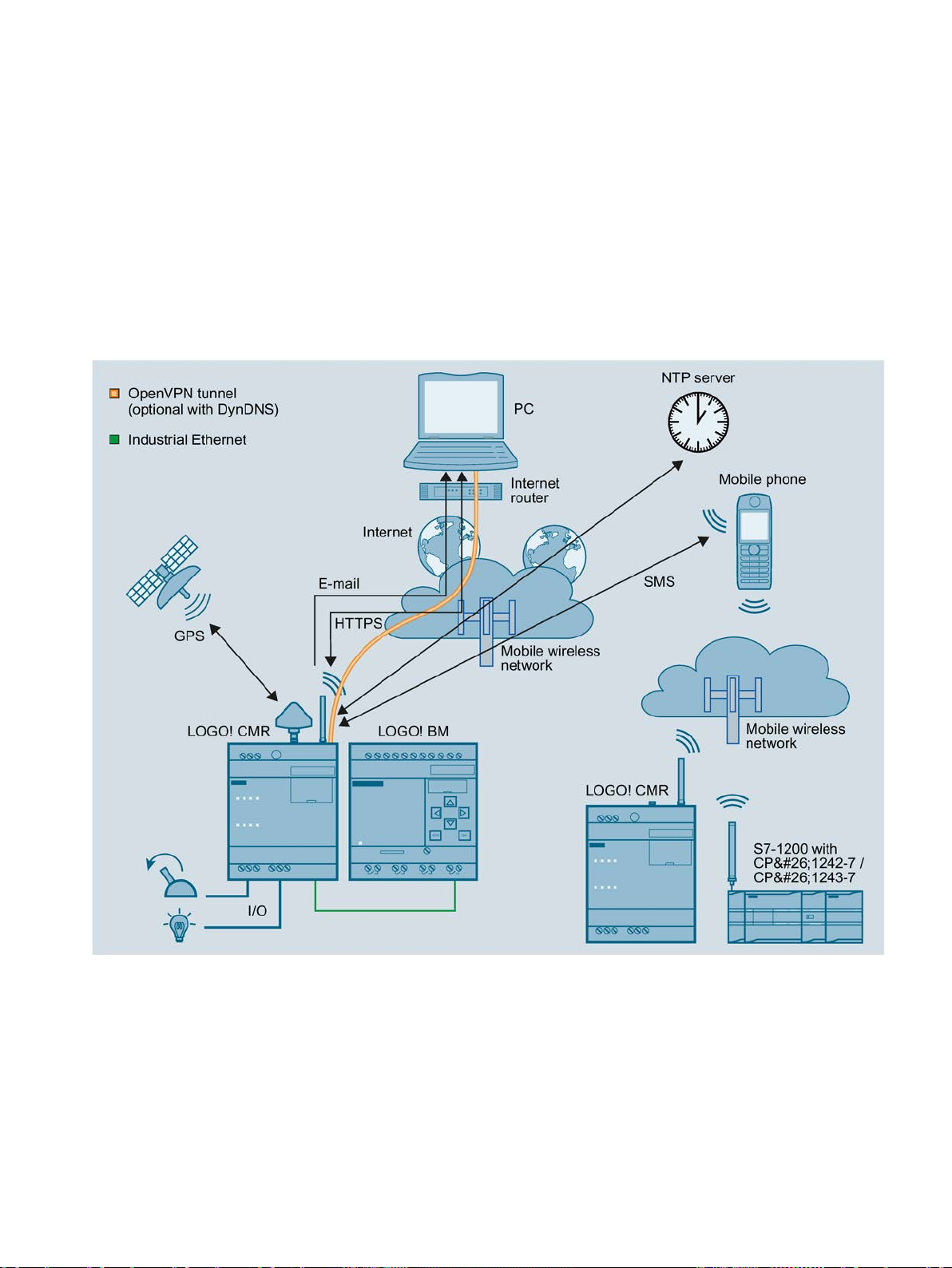
Figure 1-1 Overview of the communications functions for the LOGO! CMR
In a structure with BM you can use the CMR to access the process data: Process image,
inputs/outputs, memory bits etc.
LOGO! CMR2020, LOGO! CMR2040
Operating Instructions, 10/2016, C79000-G8976-C356-03
13

Application and functions
Mobile wireless
LOGO! CMR2020
LOGO! CMR2040
Fallback strategy
GPS
HTTPS
Station structure with CMR
CMR with BM
Stand-alone operation
1.1 Application and communications functions
In stand-alone operation (see below) you can access the I/O via the inputs and outputs of
the CMR
The information can be read out and transferred by SMS message or e-mail. An event-based
notification via SMS message or e-mail is possible, see "Mobile wireless".
With the CMR, you establish a mobile data connection to a mobile wireless network: The
following specifications are supported:
●
Mobile wireless standards:
– GSM/GPRS
●
Mobile wireless standards:
– 4G (LTE)
– 3G (UMTS)
– 2G (GSM/GPRS/EDGE)
If the establishment of a connection from the CMR2040 to the LTE network fails, the dialin falls back automatically to the next lower mobile wireless network (LTE > UMTS >
GPRS).
You will find the supported frequencies in the section Technical specifications (Page 141).
You will find the country-specific wireless approvals in section Approvals (Page 145) and on
the following Internet page;
Link: (https://support.industry.siemens.com/cs/ww/en/ps/15383/cert)
The CMR can receive position data and the time of day of a GPS system.
On a configuration PC / smartphone / tablet you can use HTTPS to access the CMR. HTTPS
is supported on both interfaces of the CMR: LAN and WAN (mobile wireless)
You can use the CMR with the following structures:
●
:
The CMR is connected locally to a BM via Ethernet. The CMR establishes the connection
to a mobile wireless network.
●
You can also operate the CMR in stand-alone mode: in other words without a connected
BM. To connect the I/O you use the two digital inputs and outputs of the CMR.
LOGO! CMR2020, LOGO! CMR2040
14 Operating Instructions, 10/2016, C79000-G8976-C356-03

Application and functions
1.2
Further functions
Functions
WBM
OpenVPN
GPS position
DynDNS
Messages (SMS / e-mail)
Reading the process image
Writing outputs
Reading signals
Access to variable memory (VM)
1.2 Further functions
The CMR supports the following functions:
●
A Web user interface (WBM - Web Based Management) for the configuration of the CMR
protected by user and password queries, see section "WBM" below.
●
Tunnel technology OpenVPN for secure data transmission via mobile wireless, see
section "OpenVPN" below.
●
– Querying position by SMS
– Forwarding position to the BM
●
Use of dynamic DNS on the WAN interface (mobile wireless)
●
– Sending and receiving SMS messages
– Sending e-mail
For information on the functions, refer to the section "Messages" below.
●
The process image of the BM can be read out by SMS message (command
"MONITOR?").
●
The two outputs of the CMR can be written by SMS.
●
With e-mail and SMS you can have read access to the process image of the BM, the
variable memory of the BM and the process image of the CMR using configurable
signals.
●
Via the variables memory, you have read and write access to the current values of
function blocks of the BM.
LOGO! CMR2020, LOGO! CMR2040
Operating Instructions, 10/2016, C79000-G8976-C356-03
15

Application and functions
Events / process image
Time-of-day synchronization
Forwarding the time of day to the BM
SD card
WBM
1.2 Further functions
●
Event configurations and reactions, for example an alarm SMS message if a value
changes in the process image.
The process image consists of the following elements that you can use for an event or
alarm configuration:
– Digital and analog inputs
– Digital and analog outputs
– Digital and analog bit memory
– Shift register
– Operator keys
– Function keys
●
– NTP
– GPS
– Mobile wireless network (depending on the mobile wireless provider)
●
●
As an option you can save the configuration data of the CMR and a copy of the
diagnostics buffer on an SD card.
You configure the CMR locally using a Web user interface (WBM) that can be displayed with
a Web browser. The WBM provides the following functions:
● Enabling receipt of GPS
● Setting the system time and synchronization of the BM
● Configuration of the CMR for sending and receiving messages
● Configuration of the LAN and WAN interface and their functions
● Configuration of the security functions
● Creation and management of users and groups
● Monitoring the CMR with a wide range of parameters and functions
● Upkeep functions such as firmware updates and restarts
● You will also receive a lot of status and diagnostics information via the WBM.
For more detailed information, refer to section Configuration (WBM) (Page 53).
LOGO! CMR2020, LOGO! CMR2040
16 Operating Instructions, 10/2016, C79000-G8976-C356-03

Application and functions
Messages
Sending SMS messages and e-mails
Receiving SMS messages
OpenVPN
1.2 Further functions
From internal events and events coming from the process reactions can be generated by the
WBM that lead to information, diagnostics and alarm SMS messages or e-mails being sent.
Using SMS messages, the outputs of the CMR and the BM can be written. The authorization
is checked by comparing the phone number of the sender with the configured phone
numbers. Password protection is optional.
Example of the SMS text for writing a single bit with the value zero:
<Password>;LOGO=VM115.1,0,BIT
Functions for simplifying SMS syntax:
● Alias SMS
Configuration of symbolic names as placeholders for the entire SMS text
● Constants for values that are repeated
Configuration of symbolic constants as placeholders for values to be written that are
repeated
● Use of signal names as parameters in SMS messages
Configuration of signals as placeholders for variables of the BM
You will find the relevant information in the following sections:
● Diagnostics > Notifications (Page 76)
● WAN > SMS (Page 92) and the following
● Users / groups > User (Page 104) and > Recipient groups (Page 106)
● Monitoring > Constants (Page 111)
● Monitoring > Message texts (Page 113)
● Monitoring > Signals (Page 113)
and
● Response of the CMR when receiving an SMS message/replying to SMS message
(Page 163) and the following
You can use the VPN technology of OpenVPN for the secure transfer of data via the mobile
wireless connection of the CMR. A VPN tunnel is established between the CMR and the
connection partner (mobile phone/tablet, PC). In this case the CMR is the OpenVPN server,
the partner (mobile phone, PC) is the OpenVPN client.
In addition to this you can use OpenVPN for direct communication with the BM if the CMR is
entered as a router with the BM.
The CMR RTU uses OpenVPN version V2.3.11.
LOGO! CMR2020, LOGO! CMR2040
Operating Instructions, 10/2016, C79000-G8976-C356-03
17

Application and functions
Diagnostics via LAN and WAN
1.3
Requirements for use
Requirements for operation
Mobile wireless contract with SIM card
Mobile wireless network
Data contract
NTP
OpenVPN
1.3 Requirements for use
OpenVPN is implemented on the CMR as a TUN device (routing mode). The following
security functions are supported:
● Encryption
The data to be transferred is encrypted with the AES-128 CBC method.
● Authentication of the connection partner
SHA-256 is used as hash algorithms for authenticating the user data.
You will find the requirements for the OpenVPN client on the VPN partner in the section
Requirements for use (Page 18).
Using the WBM you can view a diagnostics buffer for diagnostics purposes. It is also
possible to save the diagnostics buffer on the SD card or the PC.
You will find details in the section Diagnostics options (Page 131).
●
To use the mobile wireless communication via the WAN interface of the CMR, you require
a contract with a suitable mobile wireless network provider.
For more information on the contract and SIM card see below.
●
To be able to use the mobile wireless interface, there must be a mobile wireless network
within the reach of the CMR.
●
For the following data services you require a data contract with your mobile wireless
network provider:
E-mail, NTP, DynDNS, OpenVPN, HTTPS via mobile wireless
●
For time-of-day synchronization using NTP, apart from the requirements listed above
(SIM card, data contract, mobile wireless network) you also require the address data of
an NTP server.
●
Apart from the requirements listed above (SIM card, data contract, mobile wireless
network) you also require the following to use OpenVPN via the mobile wireless network:
– A public IP address for the CMR
– An OpenVPN client as communications partner (e.g. PC for access to the WBM of the
CMR)
LOGO! CMR2020, LOGO! CMR2040
18 Operating Instructions, 10/2016, C79000-G8976-C356-03

Application and functions
DynDNS
HTTPS
Time of day
Antennas
Power supply
1.3 Requirements for use
– A key compatible with the OpenVPN client (pre-shared key)
The key can be generated in the WBM of the CMR or generated by the
communications partner and imported via the WBM of the CMR.
The OpenVPN client in the Open VPN partner must support the following functions:
– OpenVPN V2.3.11 or higher
You can export the information of the Open VPN server of the CMR as a file for the client,
see section OpenVPN-PSK (Page 98).
●
To use DynDNS, apart from the requirements listed above (SIM card, data contract,
mobile wireless network) you also require the following:
– A suitable service provider
– A public IP address
– Note the section "Time of day" below.
●
– For HTTPS via mobile wireless you require a public IP address for the CMR.
– Note the section "Time of day" below.
●
When you use certificates, for example when you use HTTPS, e-mail (secure) or
DynDNS, you require the precise time of day and the precise date for checking the
certificates.
Only use antennas from the accessories program for the CMR. For more information, refer to
the section Antennas (Page 155).
● Mobile wireless
To operate the CMR, you require an antenna that is adapted to the standard of the
mobile wireless network you are using.
For the fallback behavior when using an LTE network, refer to section Application and
communications functions (Page 13).
You will find the frequency bands supported by the CMR in the section Technical
specifications (Page 141).
● GPS
If you want to use GPS, you require a suitable GPS antenna, see section Antennas
(Page 155).
You require a voltage source with a voltage between 12 VDC and 24 VDC that provides
adequate voltage or current. For more information, refer to the section Technical
specifications (Page 141).
LOGO! CMR2020, LOGO! CMR2040
Operating Instructions, 10/2016, C79000-G8976-C356-03
19

Application and functions
SIM card
Recommendations
Compatible cards
1.3 Requirements for use
You require a SIM card of your mobile wireless provider.
Note the following recommendations for the mobile wireless contract or for the SIM card:
● Where possible sign a mobile wireless contract with a provider that makes all required
functions available. Should
For example to use DynDNS a public IP address is required.
To send SMS messages, the SIM card must be enabled this function and have a phone
number.
● Avoid using a multi SIM card. This can lead to errors in time-of-day synchronization.
● Where possible sign a fixed mobile wireless contract and do not use prepaid cards.
A flat rate for SMS and data can be recommended.
If, however, you want to use a prepaid card note the following:
– If your credit has been used up, the CMR does not send an automatic warning.
– You can query your current credit with your provider.
● With the CMR2040 for faster data traffic a contract (with corresponding SIM card) is
recommended that supports the mobile wireless standard LTE.
The CMR2040 however also supports UMTS.
● Where possible, use a standard SIM card without an adapter.
● The provider often assigns a PIN (Personal Identification Number) for the SIM card.
SIM cards that are only used for the data services (see above) can be almost always
used without a PIN. You do not need to assign a PIN in the configuration of the CMR.
● The following access data for the mobile wireless network must be present:
– Access Point Name (APN)
– Depending on the service provider also name and password for the APN
– The authentication method
For more information, refer to the section Mobile wireless settings (Page 87).
The card receptacle of the CMR for the SIM card is compatible with the following card
formats:
● Mini SIM card, 25 x 15 mm (ISO/IEC 7810 ID-000)
● Micro SIM card, 15 x 12 mm (ETSI TS 102 221 V9.0.0) if an adapter exists.
● Nano SIM card, 12.3 x 8.8 mm (ETSI TS 102 221, TS 102 221 V11.0.0) if an adapter
exists.
LOGO! CMR2020, LOGO! CMR2040
20 Operating Instructions, 10/2016, C79000-G8976-C356-03
Application and functions
Optional accessories: SD card
1.4
Application examples
Possible applications
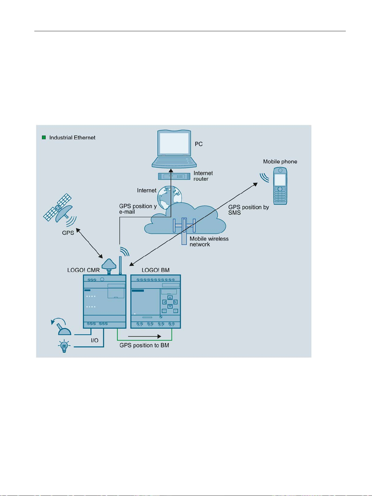
1.4.1
Mobile wireless communication by SMS / e-mail without LOGO! BM
1.4 Application examples
As an optional accessory you can use an SD card that is not supplied with the CMR. For
supported SD cards, see the appendix SD card (Page 161).
The SD card makes the following functions available:
● Storing configuration files
If you need to replace the CMR, you can also use the SD card to transfer the
configuration data of the CMR stored there to the new device. See section Replacing the
CMR (Page 137) for information on this.
● Saving diagnostics buffer entries
● Automatic saving of the entire diagnostics buffer if serious errors occur (can be
configured)
The CMR has a wide variety of possible uses in various areas of application. Below, you will
find several configuration examples for applications of the CMR.
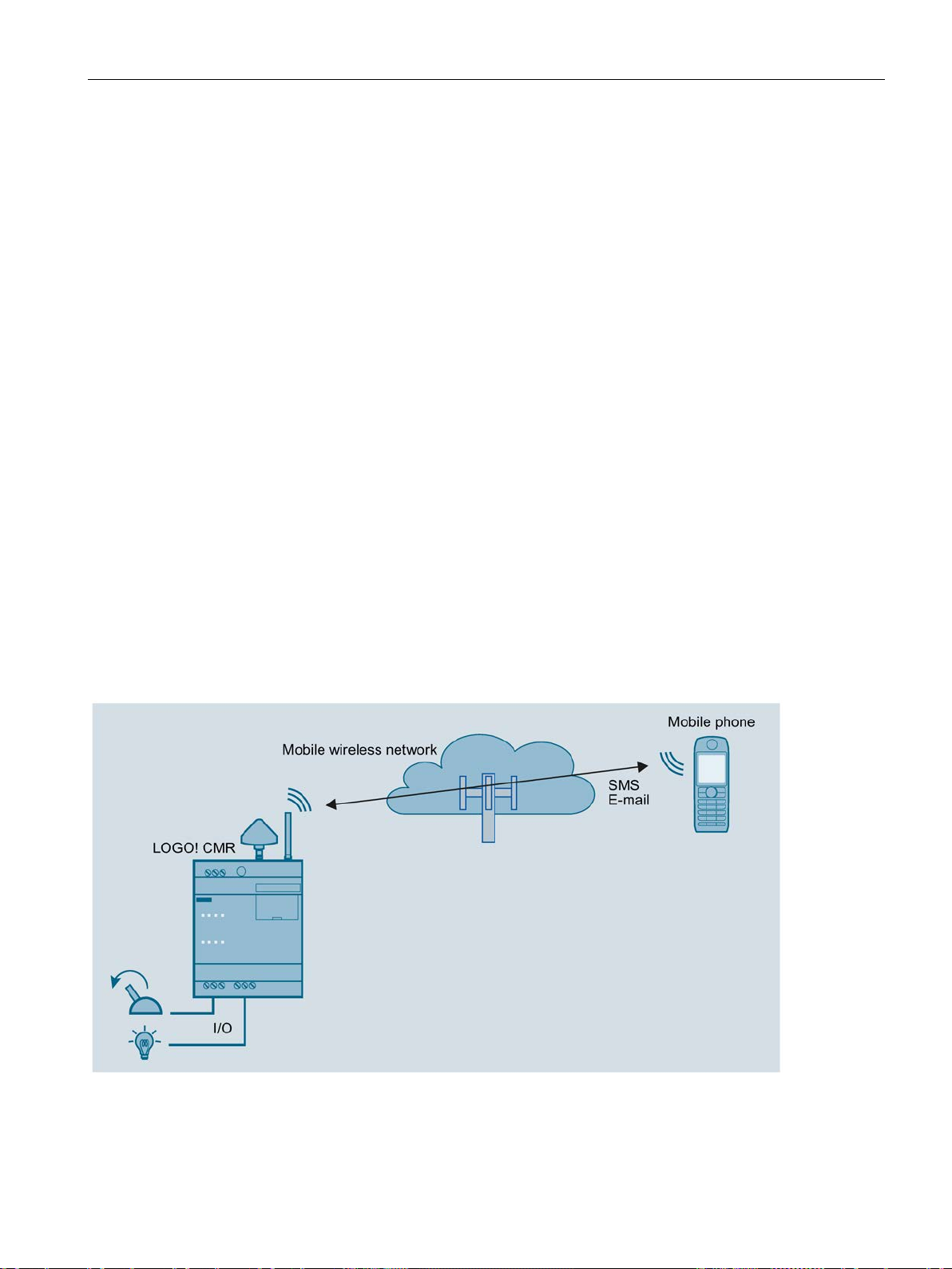
Figure 1-2 Mobile wireless communication without LOGO! BM
LOGO! CMR2020, LOGO! CMR2040
Operating Instructions, 10/2016, C79000-G8976-C356-03
21
Application and functions
Requirements
Procedure
1.4.2
Mobile wireless communication by SMS / e-mail with LOGO! BM
1.4 Application examples
You can operate the CMR without a BM being connected. If the CMR is connected to a
mobile wireless antenna, the following functions are available:
● Sending an SMS message or e-mail due to a signal at the input of the CMR
● Receiving an SMS message:
– Setting an output of the CMR
– Requesting and SMS message with status information of the CMR
Using the WBM of the CMR, you can configure events such as changing of input signals as
well as actions. The actions are triggered when configurable events occur.
● Installation, connecting up and commissioning have been completed.
● The antenna for receipt of mobile wireless is connected.
To configure access via the mobile wireless network, follow the steps below:
1. First establish a configuration connection between the CMR and a connected PC. To do
this, use an Ethernet patch cable, see Establishing a connection to the CMR (Page 63)
2. Configure the mobile wireless connection, see Mobile wireless settings (Page 87).
3. Configure the device using the WBM.
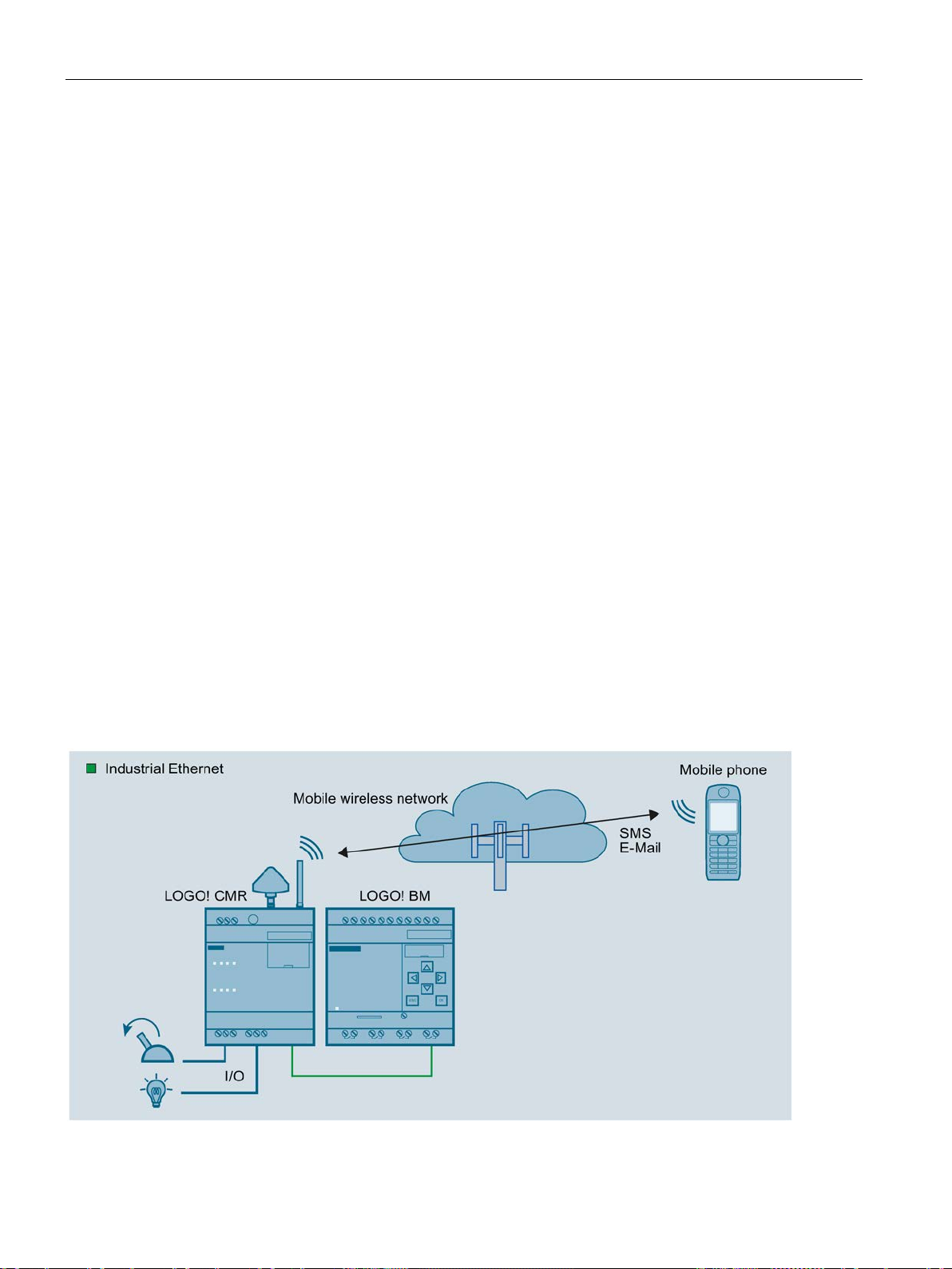
Figure 1-3 Mobile wireless communication with LOGO! BM
LOGO! CMR2020, LOGO! CMR2040
22 Operating Instructions, 10/2016, C79000-G8976-C356-03

Application and functions
Requirements
Procedure
Note
Using a switch
When using a switch, e.g. LOGO!
and PC can be operated at the same time.
1.4 Application examples
If the CMR is connected to the BM, and if you have a mobile wireless antenna connected,
you can use all the functions available in operation without a connected BM. In addition to
this, access to the LOGO! BM is expanded:
● Sending an SMS message or e-mail due to an event in the connected BM
● Receiving an SMS message:
– Triggering an action in the connected BM
– Requesting and SMS message with status information of the CMR
Configuration using the WBM also includes access to the components of the BM.
● Installation, connecting up and commissioning have been completed.
● The antenna for receipt of mobile wireless is connected.
To set up access via the mobile wireless network and to establish a connection to the BM,
follow the steps below:
1. First establish a configuration connection between the CMR and a connected PC. To do
this, use an Ethernet patch cable, see Establishing a connection to the CMR (Page 63).
2. Configure the mobile wireless connection, see Mobile wireless settings (Page 87).
3. Configure the device using the WBM.
4. When configuration is completed, disconnect the CMR from the PC.
CSM, do not disconnect the connections: BM, CMR
5. If you do not use a switch connect the CMR to the BM.
LOGO! CMR2020, LOGO! CMR2040
Operating Instructions, 10/2016, C79000-G8976-C356-03
23
Application and functions
1.4.3
Access by the PC via the Internet and mobile wireless network
1.4 Application examples
If your configuration is connected to the CMR via Internet and the mobile wireless network by
using an OpenVPN tunnel you can access the CMR and the BM.
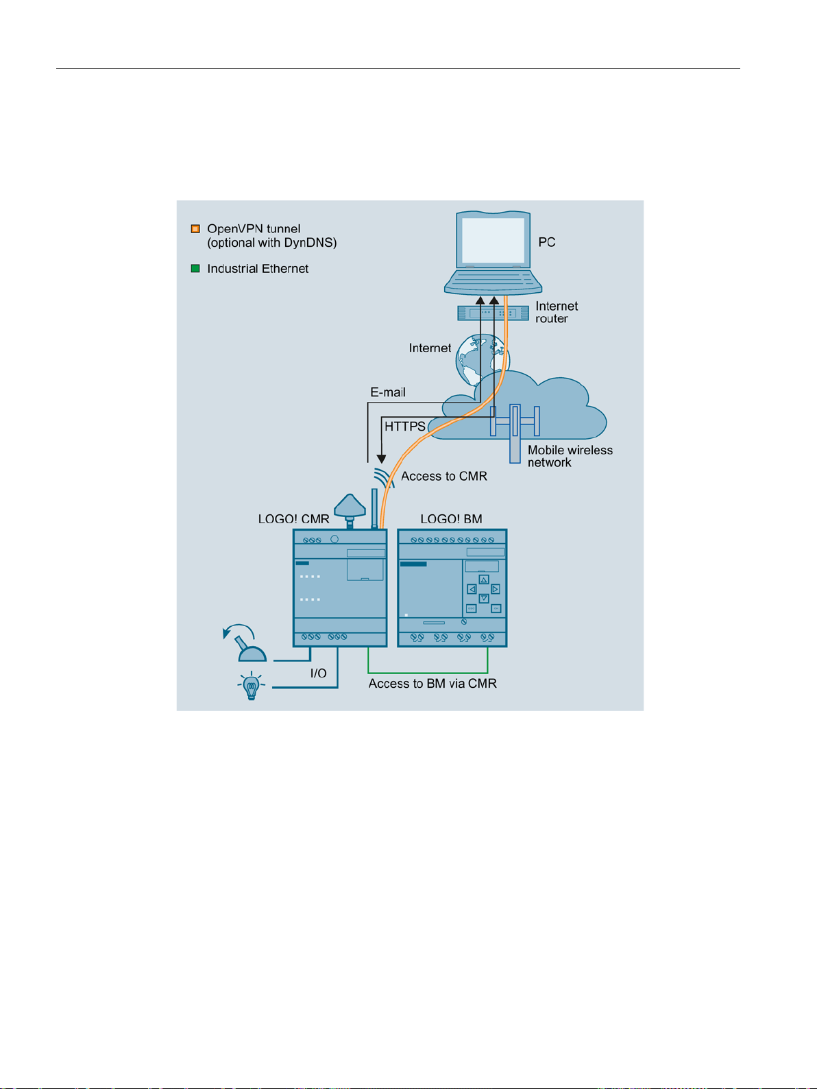
Figure 1-4 Access by the LOGO! via the Internet and mobile wireless network
You have the following options:
● Secure access from the PC to the CMR with OpenVPN
● Secure access from the PC to the BM with OpenVPN
For this application the CMR must be entered as a router in the BM.
In this way, you can for example reload the program of te BM.
● Access from the configuration PC to the CMR via mobile wireless network using HTTPS
For the procedure, refer to the section Establishing a connection to the CMR (Page 63).
● Sending e-mails optionally encrypted via STARTTLS
● Optional: Use of dynamic DNS to simplify the connection via the publicly reachable IP
address of the CMR
LOGO! CMR2020, LOGO! CMR2040
24 Operating Instructions, 10/2016, C79000-G8976-C356-03
Application and functions
Requirements
1.4.4
Position detection (GPS)
1.4 Application examples
● The services used are activated in the CMR via the WBM.
● You have contracts with suitable service providers.
Figure 1-5 Position detection (GPS)
The CMR is equipped with a GPS interface via which the position data of the LOGO! station
can be determined. If a GPS antenna is connected to the GPS interface, the following
functions are available to you:
● Detecting position data:
– Due to an event at an input of the CMR.
– Due to an event from the BM.
– Due to a received SMS message (with the mobile wireless antenna connected)
LOGO! CMR2020, LOGO! CMR2040
Operating Instructions, 10/2016, C79000-G8976-C356-03
25

Application and functions
Requirements
Procedure
Note
Using the CMR for mobile wireless communication without BM
If you use the CMR in
(Page
Note
Using a switch
When using a switch, e.g. LOGO! CSM, do not disconnect the connections: BM, CMR
and PC can be operated at the same time.
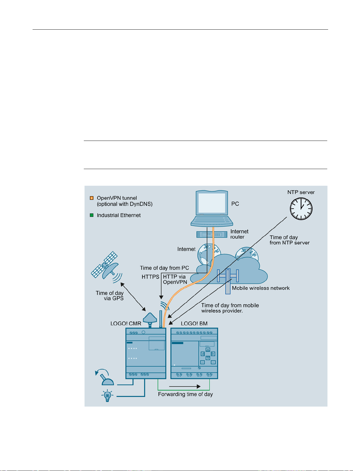
1.4.5
Time-of-day synchronization
1.4 Application examples
● Sending detected position data:
– By SMS message or e-mail
– To the BM
To be able to use the functions listed above, you first need to activate (Page 70) the GPS
interface in the WBM of the CMR. For correct position detection, the GPS signals need to be
received from three satellites.
● Installation, connecting up and commissioning have been completed.
● An GPS antenna is connected.
To set up access via the mobile wireless network and to establish a connection to the BM,
follow the steps below:
Mobile wireless communication by SMS / e-mail without LOGO! BM
21), the last two steps of the procedure described below can be omitted.
1. First establish a configuration connection between the CMR and a connected PC. To do
this, use an Ethernet patch cable.
See Establishing a connection to the CMR (Page 63)
2. Configure the mobile wireless connection:
See Mobile wireless settings (Page 87)
3. Activate GPS reception (Page 70).
4. When configuration is completed, disconnect the CMR from the PC.
5. If you do not use a switch: Connect the CMR to the BM.
The time-of-day of the CMR can be synchronized using the following three methods:
● NTP
Synchronization with an external NTP server accessible via the mobile wireless network.
● GPS
● Mobile wireless
The availability of the time of day depends on the mobile wireless provider.
LOGO! CMR2020, LOGO! CMR2040
26 Operating Instructions, 10/2016, C79000-G8976-C356-03
Application and functions
Forwarding time to the BM
Note
If you use time synchronization o
changeover on the BM to ensure a consistent time.
1.4 Application examples
You set the method used for time-of-day synchronization via the WBM in the "System" tab,
see section System Time (Page 72).
You can also have the CMR adopt the time of the configuration PC.
If you enable the time of day in the WBM, you can also make a setting in the WBM so that
the CMR also synchronizes the BM with the time of day (time-of-day forwarding). To do this
enable enable "Forward time of day to LOGO! BM".
Even if time-of-day synchronization is disabled, the time of day is forwarded to the LOGO!
BM . In this case, only the manual settings are transferred to the LOGO! BM .
f the BM via the CMR, activate the standard/daylight saving
The following figure provides an overview:
Figure 1-6 Time-of-day synchronization
LOGO! CMR2020, LOGO! CMR2040
Operating Instructions, 10/2016, C79000-G8976-C356-03
27

Application and functions
Time of day when using certificates
Note
Precise time of day for certificates
To
enable time
Requirements
Procedure
1.4 Application examples
If you use certificates for example for the e-mail or DynDNS services you need the precise
time of day.
check certificates, the precise time of day is required in the CMR. When using certificates
-of-day synchronization of the CMR.
● The CMR is mounted and connected.
● The antenna for receipt of mobile wireless is connected.
● The CMR is configured.
● Only if the time-of-day synchronization method using the GPS signal was configured: The
antenna for receipt of GPS is connected.
Follow the steps below to configure the time-of-day synchronization:
1. Establish a configuration connection between the CMR and a connected PC. To do this,
use an Ethernet patch cable.
For details, see section Establishing a connection to the CMR (Page 63).
2. Select the required method.
LOGO! CMR2020, LOGO! CMR2040
28 Operating Instructions, 10/2016, C79000-G8976-C356-03
2
2.1
Appearance of the device
Operator control/connector and display elements of the CMR
Element
Function
X10 (L+, M)
Power supply connector
SET
SET button
XR01
GPS antenna connector
XR02
Mobile wireless antenna connector
LED "L"
Power supply indicator
LED "P1"
LAN interface indicator
LED "R"
Mobile wireless signal strength indicator
LED "F"
Error/fault indicator
X50/X51
Slot for SIM and micro SD card
LED I1
Input 1 indicator
LED I2
Input 2 indicator
LED Q1
Output 1 indicator
I1
Input 1 connector
M
Ground
I2
Input 2 connector
Q1
Output 1 connector
M
Ground
Q2
Output 2 connector
X1P1
LAN connector
LED Q2 Output 2 indicator
LOGO! CMR2020, LOGO! CMR2040
Operating Instructions, 10/2016, C79000-G8976-C356-03
29
LEDs, connectors, buttons, card slots
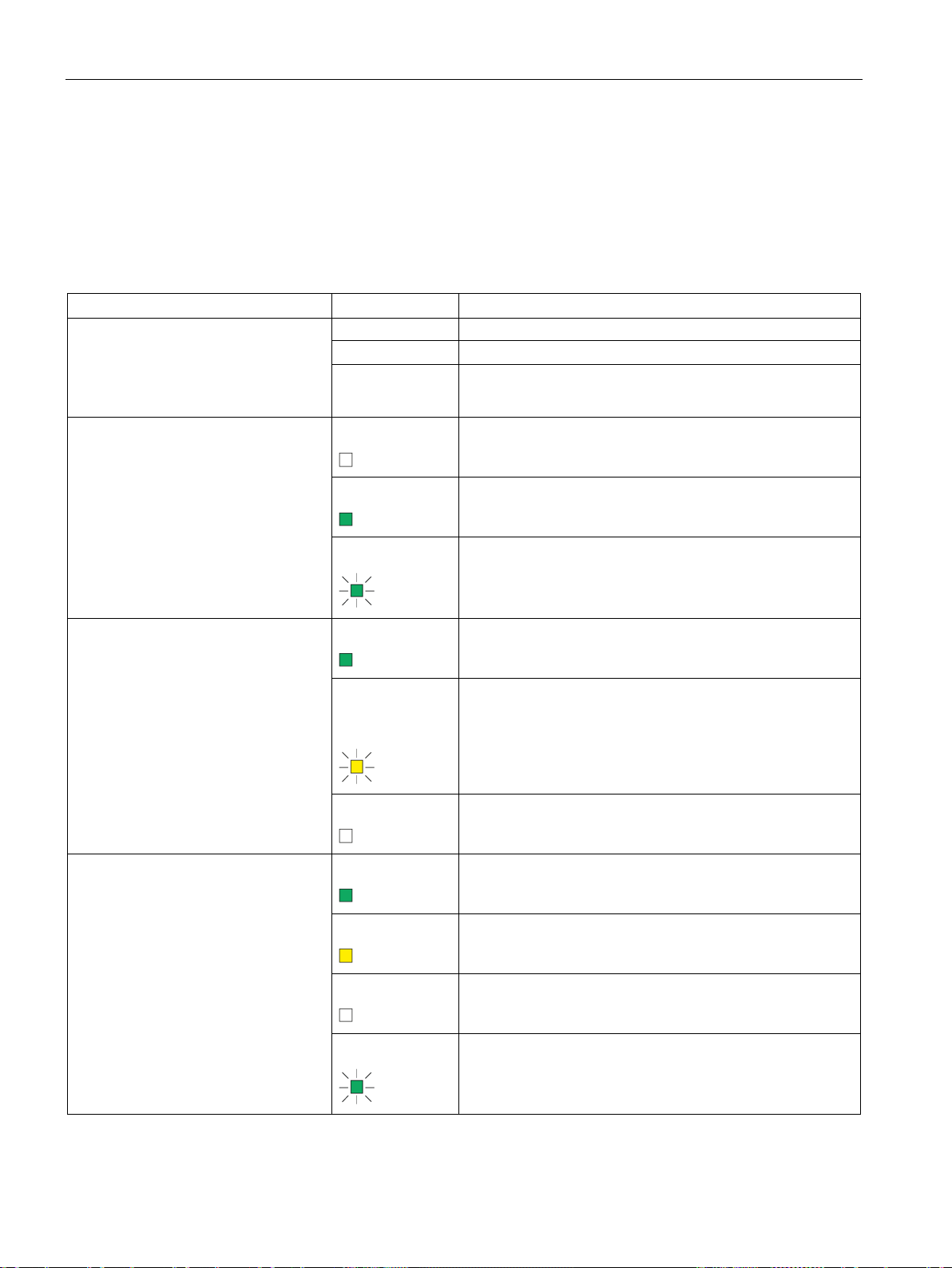
2.2
LEDs to display operation
Meaning of the LEDs
LED
Status
Meaning
Flashing
Fatal error
2.2 LEDs to display operation
The LEDs on the CMR provide information about the operating status of the device and the
two inputs/outputs.
All LEDs
Lit Firmware being updated
L
Power supply
Not lit
Off
• No voltage present or applied
• Device shut down
No external power supply connected
P1
LAN
R
Signal strength (mobile wireless)
On
Flashing
Lit green
Part flashes yellow and part lit
green
Off
Lit green
Lit yellow
Power supply connected
Initialization or change to the configuration
Connection to Ethernet is established.
Data
No connection to Ethernet or no cable connected.
Very good
Medium
Off
Flashing
LOGO! CMR2020, LOGO! CMR2040
No or very bad signal
Data
30 Operating Instructions, 10/2016, C79000-G8976-C356-03
 Loading...