

Siemens LOGO! 8, LOGO! CMK2000 User Manual

LOGO! 8: Time Switch Function for KNX
LOGO! 8, LOGO! CMK2000
https://support.industry.siemens.com/cs/ww/en/view/109745699
Siemens
Industry
Online
Support

Warranty and Liability
Time Switch Function
Entry ID: 109745699, V1.0, 04/2017
2
Siemens AG 2017 All rights reserved
Note
The Application Examples are not binding and do not claim to be complete
regarding the circuits shown, equipping and any eventuality. The Application
Examples do not represent customer-specific solutions. They are only intended
to provide support for typical applications. You are responsible for ensuring that
the described products are used correctly. These Application Examples do not
relieve you of the responsibility to use safe practices in application, installation,
operation and maintenance. When using these Application Examples, you
recognize that we cannot be made liable for any damage/claims beyond the
liability clause described. We reserve the right to make changes to these
Application Examples at any time without prior notice.
If there are any deviations between the recommendations provided in these
Application Examples and other Siemens publications – e.g. Catalogs – the
contents of the other documents have priority.
Security
information
Siemens provides products and solutions with industrial security functions that
support the secure operation of plants, systems, machines and networks.
In order to protect plants, systems, machines and networks against cyber
threats, it is necessary to implement – and continuously maintain – a holistic,
state-of-the-art industrial security concept. Siemens’ products and solutions only
form one element of such a concept.
Customer is responsible to prevent unauthorized access to its plants, systems,
machines and networks. Systems, machines and components should only be
connected to the enterprise network or the internet if and to the extent necessary
and with appropriate security measures (e.g. use of firewalls and network
segmentation) in place.
Additionally, Siemens’ guidance on appropriate security measures should be
taken into account. For more information about industrial security, please visit
http://www.siemens.com/industrialsecurity.
Siemens’ products and solutions undergo continuous development to make them
more secure. Siemens strongly recommends to apply product updates as soon
as available and to always use the latest product versions. Use of product
versions that are no longer supported, and failure to apply latest updates may
increase customer’s exposure to cyber threats.
To stay informed about product updates, subscribe to the Siemens Industrial
Security RSS Feed under http://www.siemens.com/industrialsecurity.
Warranty and Liability
We do not accept any liability for the information contained in this document.
Any claims against us – based on whatever legal reason – resulting from the use of
the examples, information, programs, engineering and performance data etc.,
described in this Application Example shall be excluded. Such an exclusion shall
not apply in the case of mandatory liability, e.g. under the German Product Liability
Act (“Produkthaftungsgesetz”), in case of intent, gross negligence, or injury of life,
body or health, guarantee for the quality of a product, fraudulent concealment of a
deficiency or breach of a condition which goes to the root of the contract
(“wesentliche Vertragspflichten”). The damages for a breach of a substantial
contractual obligation are, however, limited to the foreseeable damage, typical for
the type of contract, except in the event of intent or gross negligence or injury to
life, body or health. The above provisions do not imply a change of the burden of
proof to your detriment.
Any form of duplication or distribution of these Application Examples or excerpts
hereof is prohibited without the expressed consent of the Siemens AG.

Table of Contents
Time Switch Function
Entry ID: 109745699, V1.0, 04/2017
3
Siemens AG 2017 All rights reserved
Table of Contents
Warranty and Liability .............................................................................................. 2
1 Introduction .................................................................................................... 4
1.1 Overview ........................................................................................... 4
1.2 Mode of Operation ............................................................................. 5
2 Setup and description .................................................................................... 6
2.1 Components used ............................................................................. 6
2.2 Hardware setup ................................................................................. 7
2.3 LOGO! program ................................................................................. 7
2.3.1 Basics ............................................................................................... 8
2.3.2 Functional principle of the switching program ..................................... 9
2.3.3 Simulation mode .............................................................................. 13
2.4 Mounting the LOGO! into KNX ......................................................... 15
2.4.1 LOGO! CMK2000 parameterization ................................................. 16
2.4.2 Connecting communication objects .................................................. 20
3 Commissioning ............................................................................................ 21
3.1 Setting time and date of the LOGO! ................................................. 21
3.2 Timer parameterization .................................................................... 21
3.2.1 Weekly timer parameterization ......................................................... 21
3.2.2 Yearly timer parameterization .......................................................... 23
3.3 Downloading the program to the LOGO! .......................................... 24
3.4 Loading the KNX application program .............................................. 25
4 Operation ...................................................................................................... 28
4.1 Setting time ..................................................................................... 28
4.1.1 Parameter assignment mode at LOGO! Display ............................... 28
4.1.2 Settings via the message text .......................................................... 28
4.2 Switching the time switch function on and off centrally ..................... 31
5 Adjustments and expansions ...................................................................... 32
5.1 Enabling the web server and changing the password ....................... 32
5.2 Expansion options ........................................................................... 33
5.3 Adjusting message texts .................................................................. 34
6 Appendix ....................................................................................................... 35
6.1 Service and Support ........................................................................ 35
6.2 Links and Literature ......................................................................... 36
6.3 Change documentation .................................................................... 36
1 Introduction
Time Switch Function
Entry ID: 109745699, V1.0, 04/2017
4
Siemens AG 2017 All rights reserved
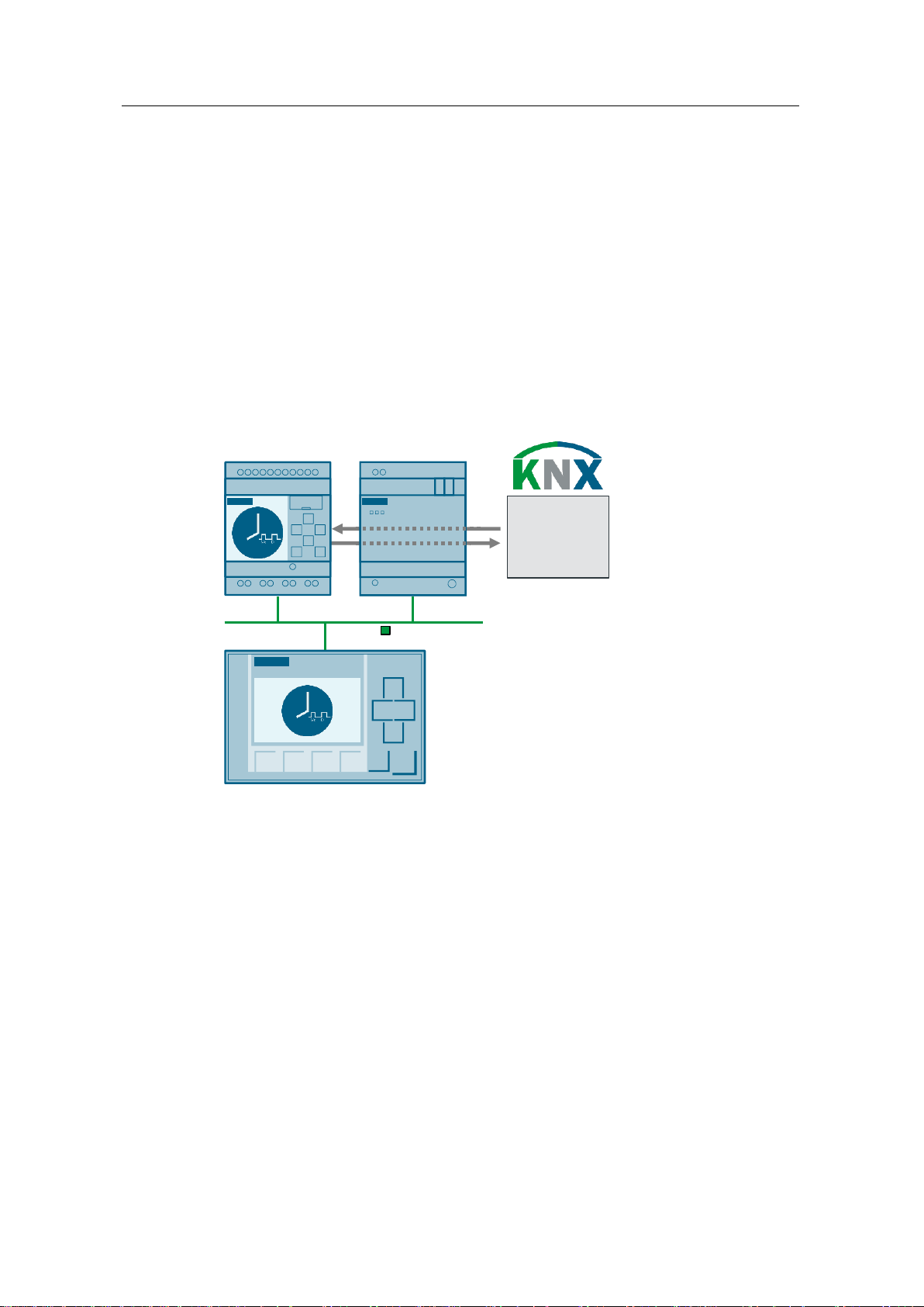
LOGO! 8 LOGO! CMK2000
ETHERNET TCP/IP
LOGO! TDE
• Buttons
• Actuators
• …
1 Introduction
1.1 Overview
With LOGO! 8 and integrated functions such as Astrotimer, Yearly and Weekly
Timer, you can quickly and easily solve many automation tasks. The LOGO! text
display (TDE) and the integrated web server of LOGO! 8 offer additional
possibilities for controlling and monitoring.
For communication in building automation, Siemens offers a solution for LOGO! 8
in form of the communication module CMK2000. The communication module
enables communication with any KNX devices via the KNX building system bus.
This application example offers you a complete time switch function for LOGO! 8
and shows you how to mount it into a KNX system via the CMK2000.
Figure 1-1: Hardware setup for the application example
Advantages
The combination of the time switch function in LOGO! 8 and the CMK2000 module
offers you the following advantages:
Switching of actuators at configurable times
Configuration of timer via the LOGO! display
Configuration of timer using the integrated Web server of the LOGO! 8
Integration of LOGO! inputs and output into a KNX system
Target group
This application example is aimed at experienced KNX users who seek to expand
their KNX system with the functionalities of a LOGO! 8.

1 Introduction
Time Switch Function
Entry ID: 109745699, V1.0, 04/2017
5
Siemens AG 2017 All rights reserved
1.2 Mode of Operation
Time switch function
The time switch function in LOGO! consists of weekly and yearly timers and offers
the following scope of functions:
Standard times:
Switching on and off on certain days of the week, at certain times.
Event times:
Switching on and off on a certain date, at a certain time (e.g. for evening
events).
Times for suppressing the time switch function:
Date and time at which the standard and event times are inoperative, e.g.
during school holidays.
Central switching on and off:
Manual switching on and off, regardless of the time settings, e.g. for
maintenance work.
Mounting into KNX
Via the LOGO! communication module CMK2000, the time switch function of the
LOGO! is integrated into a KNX system.
Via configurable communication channels of the LOGO! CMK2000, the data
between the LOGO! and the KNX devices are exchanged bi-directionally.
In this application example, a 3-Gang Button with status LEDs is used as KNX
device. A status LED indicates the status of the time switch function.
Operation
The time switch function is configured by the user.
This requires no special programming knowledge. The following options are
available:
Displaying message texts with time and date parameters at the LOGO! TDE
Displaying message texts with time and date parameters using the integrated
web server of the LOGO!
For users with programming experience, the following additional options to
configure the LOGO! time switch function are available:
In LOGO! Soft Comfort during commissioning
Configuration mode at LOGO! display
Central switching on and off is done via configured KNX buttons, digital inputs of
the LOGO!, or function buttons of the LOGO! TDE.
LOGO! TDE is an optional component whose functions (message texts and
function buttons) can also be used via the web server. You can also use a LOGO!
basic device without display.
2 Setup and description
Time Switch Function
Entry ID: 109745699, V1.0, 04/2017
6
Siemens AG 2017 All rights reserved
Component
Number
Article number
Note
LOGO! Soft Comfort
V8.1
1
6ED1058-0BA08-0YA1
Upgrade to V8.1 can be
found at
http://www.siemens.com/
logo
ETS5 Demo
1
Download link, see \6\
A maximum of 5 KNX
devices per project
LOGO! Power
1
6EP1332-1SH43
-
LOGO! 8 12/24 RCE
1
6ED1052-1MD00-0BA8
-
LOGO! CMK2000
1
6BK1700-0BA20-0AA0
Product data base for
ETS4/5:
http://www.siemens.com/
gamma-td
LOGO! TDE
1
6ED1055-4MH00-0BA1
Optional components
2-Gang Button
1 - 24 V
Siemens GAMMA KNX
Power Supply
1
5WG1 125-1AB12
320 mA
Siemens GAMMA KNX
bus coupler
1
5WG1 117-2AB12
-
Siemens GAMMA KNX
3-Gang Button
1
5WG1 223-2DB13
Product data base for
ETS4/5:
http://www.siemens.com/
gamma-td
Siemens GAMMA KNX
USB Interface
1
5WG1 148-1AB12
Required for the
programming of the KNX
devices.
Component
File name
Note
Documentation
109745699_LOGO8_TimeSwitch_KNX_DOC_en.pdf
-
LOGO! 8
Program
109745699_LOGO8_TimeSwitch_CODE_en.lsc
Requirement:
LOGO! Soft
Comfort V8.1
ETS5 project
109745699_ETS5_LOGO_for_KNX_Project_en.knxpr
oj
-
2 Setup and description
2.1 Components used
This application example was created with the following components:
Table 2-1: Hardware and software components for the application example
This application example consists of the following components:
Table 2-2: Components for the application example
2 Setup and description
Time Switch Function
Entry ID: 109745699, V1.0, 04/2017
7
Siemens AG 2017 All rights reserved
Note
LOGO! TDE is an optional component, as you can also use the functions
(message texts and function keys) via the integrated LOGO! web server.
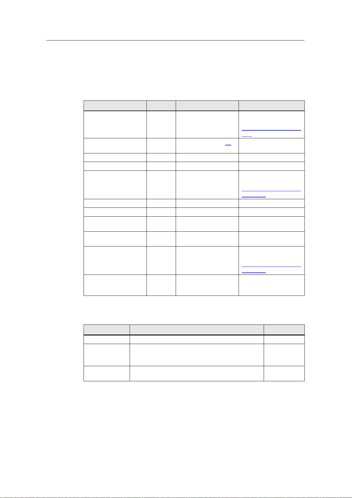
L
N
PE
24 V DC
ETHERNET TCP/IP
L N PE
-+
NL1
ML+I2I1
Button
LOGO! 8LOGO! Power
USB Interface
LOGO! CMK
KNX Power Supply
KNX Button
230 V
ML+
PA: 1.1.2
PA: 1.1.3
IP: 192.168.0.10
IP: 192.168.0.1
PA: 1.1.1
Button A1
GA: 1/1/2
Status LED A1
GA: 1/1/1
Button A2
GA: 1/1/3
IP: 192.168.0.2
ML+
LOGO! TDE
GA: Group address KNX
PA: Physical address KNX
KNX
Note
A function description of the time switch function can be found in the program
commentary in LOGO! Soft Comfort:
“Tools > Select Hardware… > Offline settings > Comment”.
Tip: Under “Tools > Options… > Print”, activate the option box “Comment” for
the function description to be printed together with the program.
2.2 Hardware setup
The following figure shows the hardware setup for this application example.
Figure 2-1: Hardware setup
2.3 LOGO! program
The time switch function consists of weekly and yearly timer function blocks.
The function blocks are logically linked with each other and with the input signals in
order to switch an output on or off at certain times or manually.
2 Setup and description
Time Switch Function
Entry ID: 109745699, V1.0, 04/2017
8
Siemens AG 2017 All rights reserved
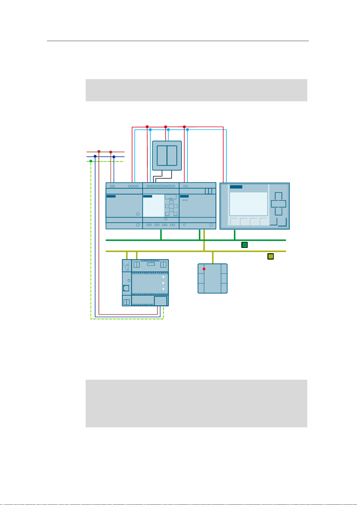
2.3.1 Basics
Week timer
Every week timer has three setting cams via which you can parameterize a time
slot each. Via the cams, you can set the switch on and off times (see Table 3-1).
If the output has not yet been set, the week timer will switch it on at a switch-on
time.
If a switch-off time is configured, the output of the week timer will be reset at the
switch-off time.
The switching state of the week timer depends on all three cams, No 1, No 2 and
No 3.
Figure 2-2: Week timer function block
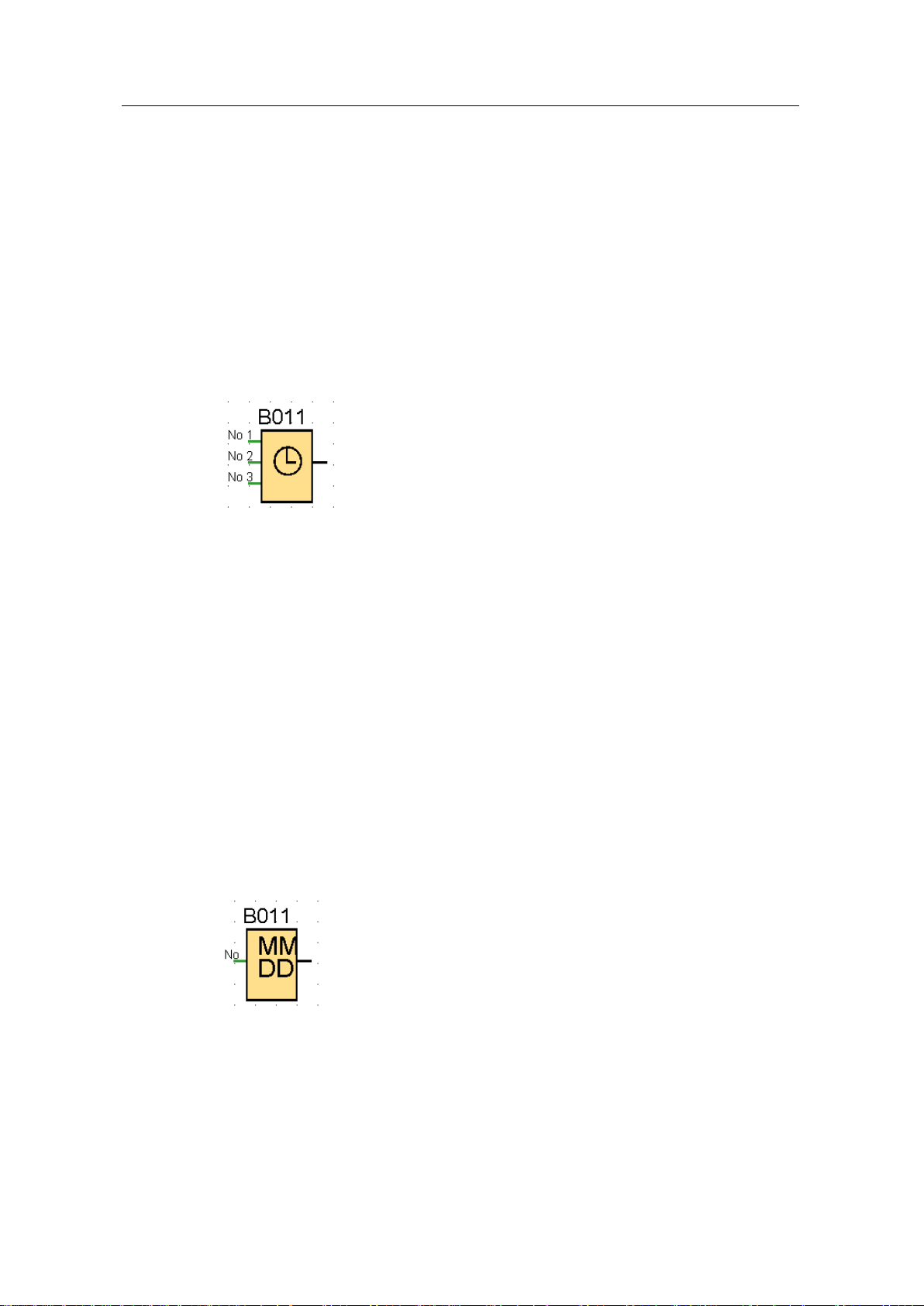
Yearly timer
On certain dates, the yearly timer switches the output on or off.
The switch-on time indicates month and day, on which the timer is set.
The switch-off time indicates month and day, on which the timer is reset again.
(see Table 3-2).
The function offers two repeat patterns:
Yearly:
Timer output switches on every year at the specified month and day of the
switch-on time and remains switched on until the specified month and day of
the switch-off time.
Every month:
Timer output switches on every month at the specified day of the switch-on
time and remains switched on until the specified day of the switch-off time.
The switch-on year specifies the first year in which the timer will be activated.
The switch-off year specifies the last year in which the timer will be switched off.
Figure 2-3: Yearly timer function block
Internal clock buffering
The internal clock of a LOGO! 8 is buffered by an accumulator and continues to run
in the event of a power supply failure.
The buffering time is influenced by the ambient temperature. At 25 °C (77 °F), it is
around 20 days.
2 Setup and description
Time Switch Function
Entry ID: 109745699, V1.0, 04/2017
9
Siemens AG 2017 All rights reserved
Signals
Function
Description
Input I1
Central switching on of
output Q1
Button on the LOGO!
Function key F1
LOGO! TDE or, alternatively, via the
LOGO! web server
Flag M50
Connection to KNX
Input I2
Central switching off of
output Q1
Button on the LOGO!
Function key F2
LOGO! TDE or, alternatively, via the
LOGO! web server
Flag M51
Connection to KNX
Output Q1
Output signal of the
time switch function
Switching of a load (e.g. a lamp) and
connection to KNX (e.g. actuator)
1 2 3
4
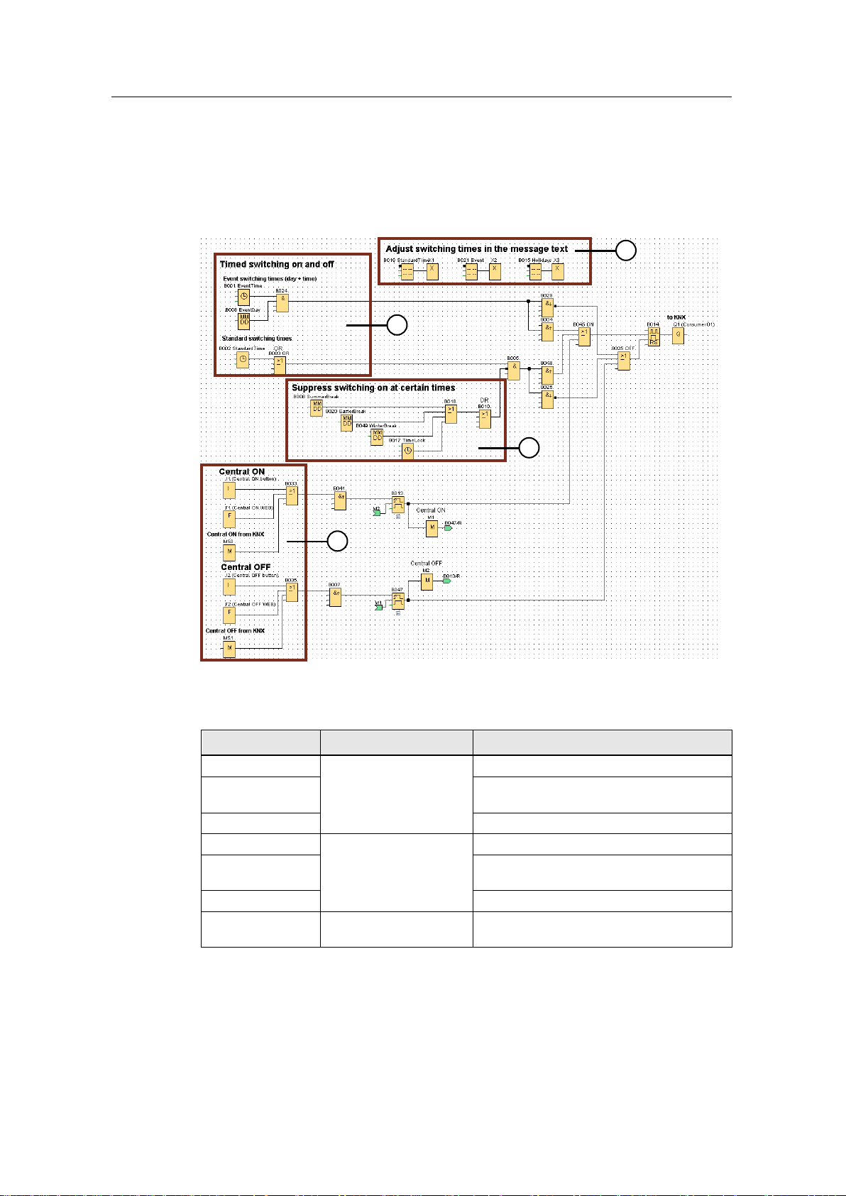
2.3.2 Functional principle of the switching program
The following figure provides an overview of the entire switching program for the
time switch function. The individual positions (1) to (4) will be discussed during the
course of this chapter.
Figure 2-4: Overview switching program
The following table shows the input and output signals of the time switch function:
Table 2-3: Signals in the LOGO!
2 Setup and description
Time Switch Function
Entry ID: 109745699, V1.0, 04/2017
10
Siemens AG 2017 All rights reserved
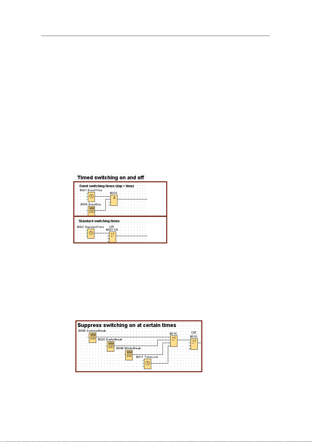
1. Time-controlled switching on and off
The combination of different switching times expands the time switch function as
follows.
Standard switching time
Via the week timer function block "B002 StandardTime”, the standard switching
time is defined.
Via the function block, it is set, on which weekdays and at which time the time
switch function switches the output Q1 on and off.
Event switching time
By linking the week timer "B001 EventTime" and yearly timer "B008 EventDay"
function blocks, an event switching time is defined.
Via the function blocks, the date and time is set for when the time switch function
switches the output Q1 on and off.
Figure 2-5: Blocks for time-controlled switching on and off
2. Suppress switching on at certain times
With the yearly timers “B006 SummerBreak”, “B020 EasterBreak” and “B049
WinterBreak”, a time period (e.g. holidays) can be defined during which the switch-
on via the standard switching times is suppressed.
With the weekly timer “B017 TimeLock”, it can be defined, on which weekdays and
at which time the switch-on via the standard switching times is suppressed.
The event switching times are not suppressed and continue to switch. This allows a
planned switch-on and off, despite the suppressed standard switching times.
Figure 2-6: Blocks for suppressing standard switching times

2 Setup and description
Time Switch Function
Entry ID: 109745699, V1.0, 04/2017
11
Siemens AG 2017 All rights reserved
1
2
3. Central switching on and off
1. Via the input I1, the function key F1 or the flag M50 (signal from the KNX), the
output of the time switch function is switched on centrally.
2. Via the input I2, the function key F2 or the flag M51 (signal from the KNX), the
output of the time switch function is switched off centrally.
The central switching on and off will be overwritten with the next impulse from the
set switching times.
Figure 2-7: Blocks for central switching on and off
 Loading...