

Siemens LMV52 series, LMV52.4 series User Manual
Based on the following
software versions:
LMV50... : V10.20
LMV51... : V05.10
LMV51.3… : V05.10
LMV52.2.. : V05.10
LMV52.4... : V10.20
Int. LR module: V02.10
Int. VSD module: V01.50
A
ZL52...: V05.00
PLL52...: V01.50
CC1A7550.5en
07.07.2015
Building Technologies Division
LMV52…
Burner management system for forced draft
burners
LMV52.4…:
- COx supervision and control
User Manual
The LMV5 and this User Manual are intended for OEMs which integrate the LMV5
in their products!
Note!
This documentation is only valid together with the LMV5... Basic
Documentation P7550.

2/17
Building Technologies Division Anwenderdokumentation LMV5... CC1A7550.5en
Contents 07.07.2015
Contents
1 Supplementary documentation .................................................................... 3
2 Warning notes ................................................................................................ 4
3 Typographical conventions .......................................................................... 4
4 COx supervision and control ........................................................................ 5
4.1 General ............................................................................................................ 5
4.2 Compatibility of the COx functions ................................................................... 5
4.3 Functioning principle of COx supervision ......................................................... 5
4.4 Hardware prerequisite / Connection diagram .................................................. 6
4.5 Operating modes of COx supervision .............................................................. 6
4.5.1 COx Alarm operating mode ............................................................................. 7
4.5.2 COx Control operating mode ........................................................................... 8
4.6 Increasing the manipulated variable in case of COx signal (O2ModOffset,
formerly O2Offset) ........................................................................................... 9
4.7 Setting notes .................................................................................................. 10
4.7.1 Parameterizations .......................................................................................... 10
4.7.2 Setting fuel-air ratio control ............................................................................ 10
4.7.3 Setting the O2 trim controller ......................................................................... 11
4.7.4 Setting the COx supervision .......................................................................... 11
4.8 Display on the AZL52 ..................................................................................... 12
4.9 Displaying the O2 trim controller status ......................................................... 12
5 List of error messages of LMV5 system .................................................... 13
6 Revision history ........................................................................................... 17

3/17
Building Technologies Division User Manual LMV5... CC1A7550.5en
Supplementary documentation 07.07.2015
1 Supplementary documentation
Product type
Type of documentation
Documentation number
AZL5...
User Documentation AZL5... Modbus
A7550
LMV5... User Documentation
Basic diagram of LMV5... for 2 types of gas
A7550.1
LMV5... User Documentation
Basic diagram of LMV5... for 2 types of liquid fuel
A7550.3
LMV5... User Documentation
Assembly of VKF41...C gas damper with ASK33.4 mounting kit
to the SQM45.295A9 actuator
A7550.4
LMV5... Setting Lists (parameter and error list) I7550
ACS450 Operating Instructions J7550
LMV5… Installation Guide J7550.1
LMV5... Data Sheet N7550
LMV5... Basic Documentation P7550
LMV5... Product Range Overview
This document contains a complete overview
Q7550
AZL52 / LMV51 User Manual U7550
AZL52 / LMV51 User Manual U7550.1
AZL52 / LMV52 User Manual U7550.2
AZL52 / LMV52 User Manual U7550.3
AZL52 / LMV50 User Manual U7550.4
AZL52 / LMV50 User Manual U7550.5
4/17
Building Technologies Division User Manual LMV5... CC1A7550.5en
Warning notes 07.07.2015
2 Warning notes
Warning!
The safety, warning, and technical notes given in the Basic Documentation on
the LMV5 (P7550) apply fully to the present document also!
To avoid injury to persons, damage to property or the environment, the following
warning notes must be observed!
The LMV5 is a safety device! Do not open, interfere with or modify the unit.
Siemens will not assume responsibility for any damage resulting from
unauthorized interference!
3 Typographical conventions
Safety notes
This User Manual contains information which must be observed to ensure your
personal safety and to prevent damage to equipment and property. The instructions
and notes are highlighted by warning triangles and arrows and are presented as
follows, depending on the hazard level:
Warning
means that death, severe personal injury or substantial
damage to property can occur if adequate
precautionary measures are not taken.
Note draws your attention to other information about the
product and its handling contained in other pieces of
documentation.
Only qualified personnel are allowed to commission and operate the unit. Qualified
personnel in the context of the safety-related notes contained in this document are
persons who are authorized to commission, ground and tag devices, systems and
electrical circuits in compliance with established safety practices and standards.
Note the following:
The unit may only be used on applications described in the technical documentation
and only in connection with third-party products and components approved or
recommended by Siemens.
The products can only function correctly and safely if shipped, stored, set up and
installed correctly, and operated and maintained as specified.
Qualified personnel
Correct use
5/17
Building Technologies Division User Manual LMV5... CC1A7550.5en
COx supervision and control 07.07.2015
4 COx supervision and control
4.1 General
Note!
The COx sensor is not included in the Siemens AG scope of delivery.
OEM customer is responsible for checking that the sensor is suitable for the
functions described below.
4.2 Compatibility of the COx functions
The new COx functions are available from the following software versions:
- PLL52 from software version V01.40
(as this requires a supply air sensor temperature range of >400 °C).
- LMV52.4 from software version V10.10
4.3 Functioning principle of COx supervision
For the purpose of supervising the COx quantities during combustion, the LMV52.4
offers the option of connecting a COx measurement transducer to the PLL52.
The states of the COx measurement transducer switching output have the following
meanings:
Contact open: COx present
Contact closed: No COx present
These are evaluated by the LMV52.4 when COx supervision is active.
When COx supervision is active, line breaks, faults in the PLL52, and faults in the bus
communication between the LMV52.4 and PLL52 result in a safety shutdown. This is
also the case during O2 trim control.
Warning!
The connections of the COx sensor to the LMV52.4, and the COx functions in
the LMV52.4, are not established in a fail-safe manner.
6/17
Building Technologies Division User Manual LMV5... CC1A7550.5en
COx supervision and control 07.07.2015
4.4 Hardware prerequisite / Connection diagram
The following hardware is required for COx supervision with LMV52.4:
COx sensor with a potential-free switching contact (NO contact).
The COx limit value at which the contact switches is defined in the COx
measurement transducer.
The COx sensor must be suitable for the fuels being used.
The PLL52, input X87 must be available for the COx sensor connection:
- For this, the supply air temperature sensor for calculating the firing efficiency can,
alternatively, be connected to input X60 of the load controller and activated by
means of the PLL52 parameter AirTempX60PT1000.
Parameter AirTempX60PT1000 (deactivated, activated)
- The Startmode parameter for O2 trim control must be set to standard or
IgnPtWoutTC, as all other start modes require a temperature sensor at input
X87 of the PLL52. In terms of the CO functions, we recommend using the
standard start mode only.
Parameter Startmode (standard, Ign Load TC, IgnPtWithTC, IgnPtWoutTC)
If input X87 on the PLL52 is used to connect the COx sensor, the PLL52 parameter
SupAirTempSens must be set to Pt1000.
COx control is only possible as of PLL52 software version V01.40, as this requires
a temperature range for the supply air temperature sensor of >400 °C.
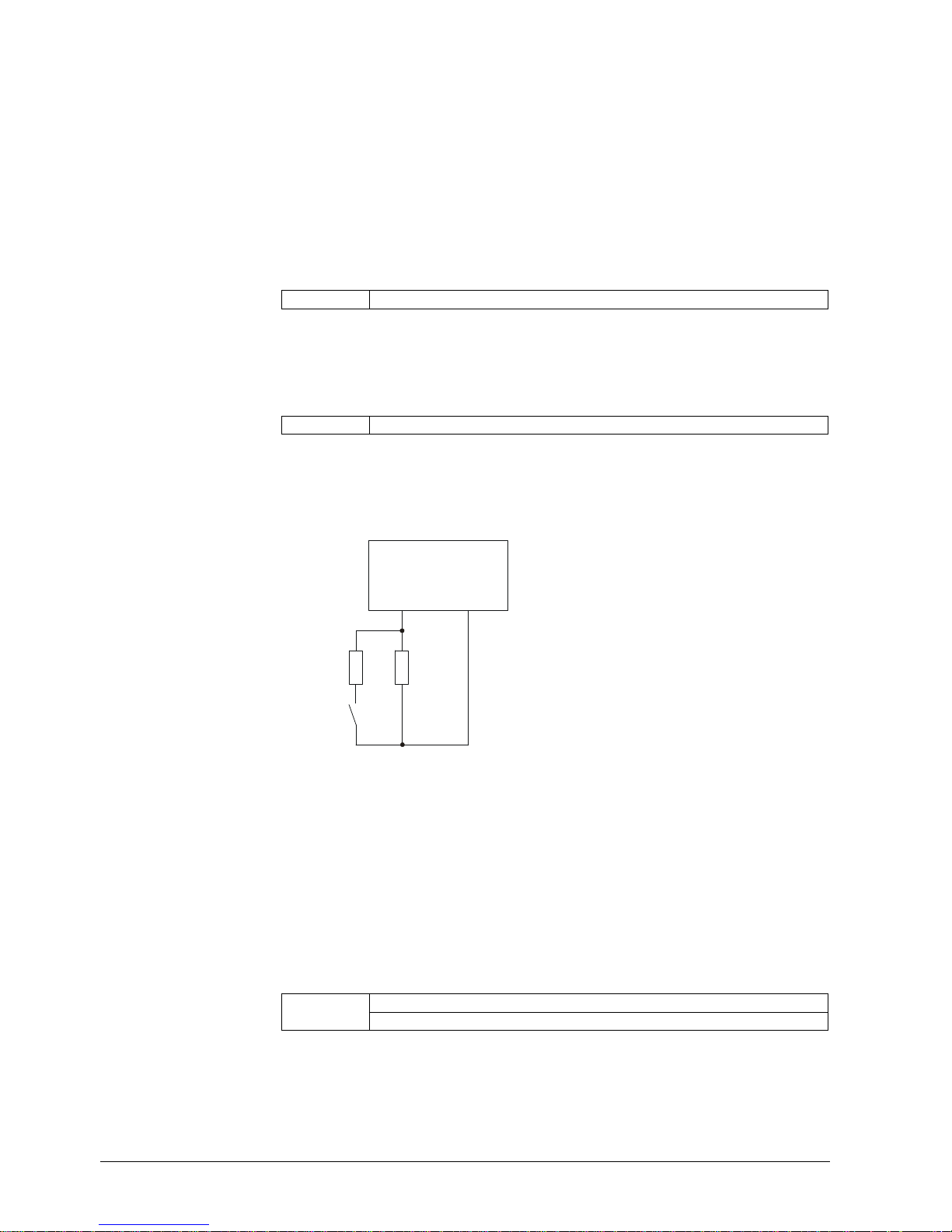
R1 R2
COxmax
X87
Pin 2
X87
Pin 1
PLL52...
7550d46/0712
- Resistor R1: 7.15 kΩ (±10%)
- Resistor R2: 3.6 kΩ (±10%)
- Relay in no-load status: COx threshold exceeded
- Relay switched: COx threshold not achieved
4.5 Operating modes of COx supervision
With the OptgMode COx parameter, one of the two COx operating modes COx Alarm
or COx Control can be set, and the COx functions deactivated.
Parameter Gas: OptgMode COx (deactivated / COx Alarm / COx Control)
Oil: OptgMode COx (deactivated / COx Alarm / COx Control)
Suggested wiring
 Loading...