

Siemens LGB21.330A27, LGB21.350A27, LGB21.230A27, LGB21.350A17, LGB21.130A27 Datasheet
...
CC1N7435en
11.01.2007
Building Technologies
HVAC Products
7
435
Burner Controls LGB...
Burner controls for the supervision of 1- or 2-stage gas or gas / oil burners of
small to medium capacity (typically up to 350 kW), with or without fan, in intermittent operation.
The LGB... and this Data Sheet are intended for use by OEMs which integrate the
burner controls in their products!
Use
The LGB... burner controls are used for the startup and supervision of 1- or 2-stage gas
or gas / oil burners in intermittent operation.
Depending on the type of burner control used, the flame is supervised either by an
ionization probe, a blue-flame detector QRC1... for forced draft gas / oil burners, or a
UV detector QRA... (with auxiliary unit AGQ1...A27).
In connection with the respective adapters, the LGB... burner controls replace their
predecessor types LFI7... and LFM1... (also refer to «Replacement types» under «Ordering»).
- Automatic forced draft burners for gaseous fuels to EN 676
- Gas burner controls to EN 298
- Undervoltage detection
- Air pressure supervision with function check of the air pressure switch during
startup and operation
- Electrical remote reset facility
- LGB41... for use with atmospheric gas burners
2/22
Building Technologies CC1N7435en
HVAC Products 11.01.2007
Warning notes
To avoid injury to persons, damage to property or the environment, the following
warning notes should be observed!
Do not to open, interfere with or modify the unit!
• All activities (mounting, installation and service work, etc.) must be performed by
qualified staff
• Before performing any wiring changes in the connection area of the LGB..., completely isolate the burner control from the mains supply (all-polar disconnection)
• Ensure protection against electric shock hazard by providing adequate protection
for the burner control’s connection terminals
• Each time work has been carried out (mounting, installation, service work, etc.),
check to ensure that wiring is in an orderly state and make the safety checks as
described in «Commissioning notes»
• Check to ensure that wiring is in an orderly state
• Press the lockout reset button only manually (apply a force of no more than 10 N),
without using any tools or pointed objects
• Fall or shock can adversely affect the safety functions. Such units must not be put
into operation, even if they do not exhibit any damage
Mounting notes
• Ensure that the relevant national safety regulations are complied with
Installation notes
• Always run the ignition cables separate from the unit and other cables while observing the greatest possible distance
• Do not mix up live and neutral conductors
• Install switches, fuses, earthing, etc., in compliance with local regulations
• Ensure that the maximum permissible current ratings will not be exceeded (refer to
«Technical data»)
• Do not feed external mains voltage to the control outputs of the unit. When testing
the devices controlled by the burner control (fuel valves, etc.), the LGB... must not
be connected
• To isolate the burner control from the mains supply, use an all-polar switch with a
contact gap of at least 3 mm
• Secure the earthing lug in the base with a metric screw and a lockwasher
• In the case of burners with no fan, the AGK25 must be connected to terminal 3 as
a burden, or else the burner cannot reliably start
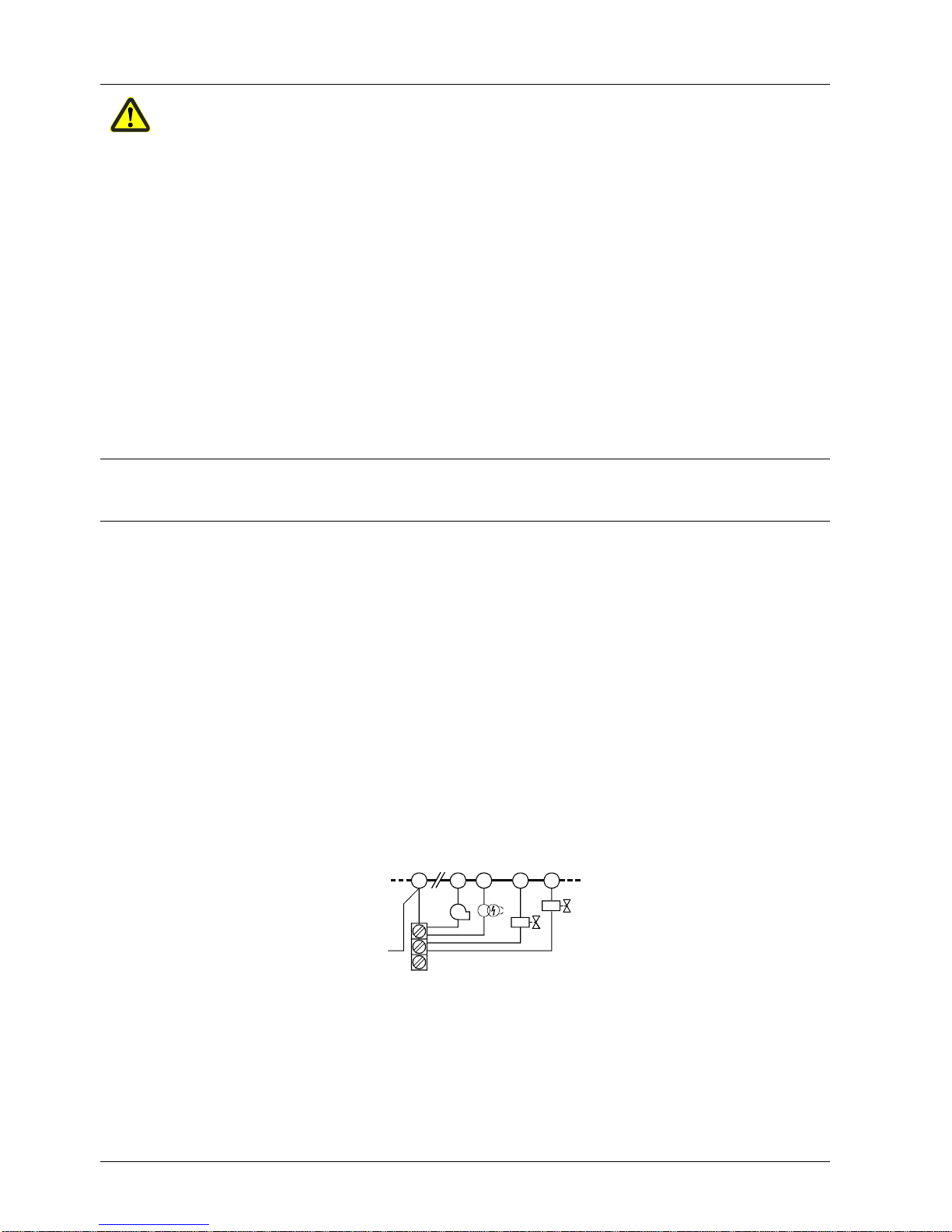
• For safety reasons, feed the neutral conductor to the neutral distributor in the plug-
in base, or to terminal 2. Connect the burner components (fan, ignition transformer
and gas valves) as represented in the figure 7435a14, to the neutral distributor as
shown below. The connection between neutral conductor and terminal 2 is prewired in the base
Example
23
7
4
5
M
N
7435a14/0601
Z
V1
V2
Legend
V... Fuel valve
M Fan motor
Z Ignition transformer
Correct wiring of neutral conductors!
3/22
Building Technologies CC1N7435en
HVAC Products 11.01.2007
Electrical connection of flame detectors
It is important to achieve practically disturbance- and loss-free signal transmission:
• Never run detector cables together with other cables
– Line capacitance reduces the magnitude of the flame signal
– Use a separate cable
• Observe the permissible length of the detector cables (refer to «Technical data»)
• The ionization probe and the ignition electrode are not protected against electric shock
hazard
• Locate the high-voltage ignition electrode and the ionization probe such that the ignition
spark cannot arc over to the ionization probe (risk of electrical overloads) a nd that it
cannot adversely affect the supervision of ionization
• With both ionization current and UV supervision, the cable length for flame detection must not exceed 20 m
• Insulation resistance
– Must be a minimum of 50 MΩ between ionization probe and ground
– Soiled detector holders reduce the insulation resistance, thus supporting cree page currents
– Prerequisite is not only high-quality heat-resistant insulation of the probe’s
cable, but also of the ionization probe itself (ceramic holder)
• Earth the burner in compliance with the relevant regulations; earthing the boiler
alone does not suffice
• The connection diagr ams show the burner controls with earthed neutral conductor. In
networks with nonearthed neutral conductor and ionization current su pervision, terminal
2 must be connected to the earth conductor via an RC unit (type reference
ARC 4 668 9066 0). It must be made certain that local regulations are complied with
(e.g. protection against electric shock hazard) since AC 230 V / 50 Hz mains voltage
produces peak leakage currents of 2.7 mA
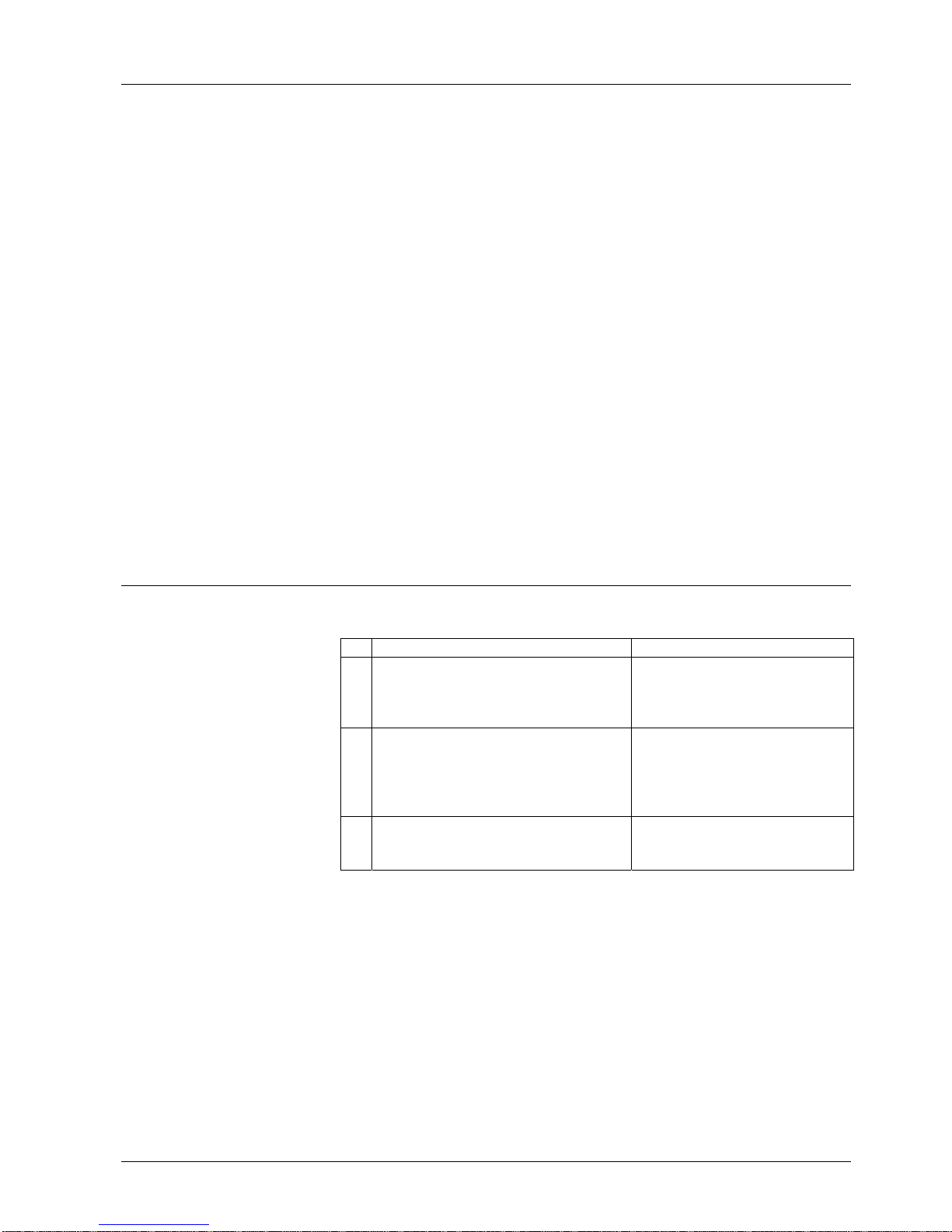
Commissioning notes
• When commissioning the plant for the first time or when doing maintenance work,
make the following safety checks:
Safety check to be carried out Anticipated response
a) Burner startup with previously inter-
rupted line to the ionization probe and
flame detector darkened in the case of
QRA... or QRC1...
Lockout at the end of «TSA»
b) Burner operation with simulated loss of
flame. For that purpose, cut off the gas
supply (e.g. disconnect the fuel valve
while ensuring protection against electric shock hazard)
Immediate lockout
c) Burner operation with simulated air
pressure failure (not with atmospheric
burners)
Immediate lockout
4/22
Building Technologies CC1N7435en
HVAC Products 11.01.2007
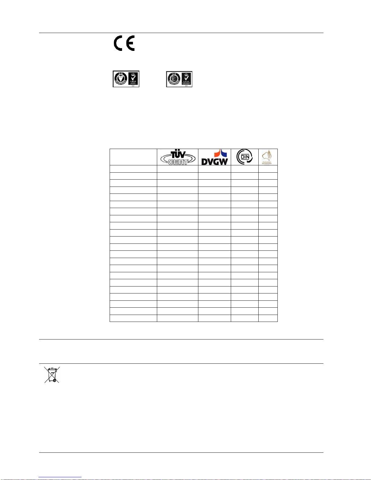
Standards and certificates
Conformity to EEC directives
- Electromagnetic compatibility EMC (immunity)
- Low-voltage directive
- Directive for gas appliances
89 / 336 / EEC
73 / 23 / EEC
90 / 396 / EEC
ISO 9001: 2000
Cert. 00739
ISO 14001: 2004
Cert. 38233
• Identification code to EN 298
- LGB21... / LGB22... F T L L X N with 2-stage operation
- LGB32... F M L L X N with 2-stage operation
- LGB41... A B L L X N with 2-stage operation
(«BV1 + BV2» or «ZBV + BV2») A M L L X N with 1-stage operation
LGB21.130A17 x x --- --LGB21.130A27 x x x x
LGB21.230A27 x x x --LGB21.330A27 x x x --LGB21.350A17 x x --- --LGB21.350A27 x x x x
LGB21.550A27 x x x x
LGB22.130A27 x x x x
LGB22.230B27 x x x --LGB22.330A17 x x --- --LGB22.330A27 x x x x
LGB22.330A270 x x x --LGB32.130A27 x x x x
LGB32.230A17 x x --- --LGB32.230A27 x x x --LGB32.330A17 x x x --LGB32.330A27 x x x --LGB32.350A17 x x x --LGB32.350A27 x x x x
LGB41.255A27 x x --- x
LGB41.258A17 x x --- --LGB41.258A27 x x --- x
Service notes
• Use KF8872 service adapter for short periods of time only
Disposal notes
The unit contains electrical and electronic components and must not be disposed of
together with household waste.
Local and currently valid legislation must be observed.
5/22
Building Technologies CC1N7435en
HVAC Products 11.01.2007
Mechanical design
The housing is made of impact-proof, heat-resistant and flame-retarding plastic.
It is of plug-in design (measuring 91 x 62 x 63 mm, including the base) and engages
audibly in the base.
The housing accommodates the
- programming mechanism with the synchronous motor
- electronic flame signal amplifier (ionization) with the flame relay and the other
switching devices
- lockout reset button with its integrated fault indication lamp
Type summary
The type references given below apply to LGB... burner controls without plug-in base
and without flame detector. For ordering information on plug-in bases and other accessories, refer to «Mechanical design», «Ordering», «Flame supervision ...» and «Technical data».
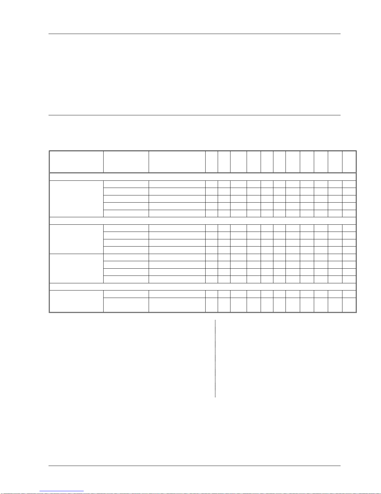
Flame detector Type reference Approved in: tw/s t1/s TSA/s t3n/s t3/s t4/s t9/s t10/s t11/s t12/s t20/s
6) 3) 3)
ca. min. max. ca. ca. ca. max. min. max. max. ca.
Burner controls for 2-stage burners without contr ol of act uator
Ionization probe (ION)
LGB21.130A27 4)7)
CH, EU, S, SF 8 7 3 2.4 2 8 --- 5 --- --- 6
LGB21.230A27 5)
CH, EU, S, SF 8 15 3 2.4 2 8 --- 5 --- --- 38 or UV detector QRA...
with AGQ1...A27
LGB21.330A27 5)
CH, EU, H, S, SF 8 30 3 2.4 2 8 --- 5 --- --- 23
LGB21.350A27 5)7)
CH, EU, H, S, SF 8 30 5 4 2 10 --- 5 --- --- 21
LGB21.550A27 5)
AUS, CH, EU 8 50 5 4 2 10 --- 5 --- --- 2
Burner controls for 2-stage burners with control of actuator
Ionization probe (ION)
LGB22.130A27 4)
CH, EU, N, S 9 7 3 2.4 3 8 --- 4 12 12 21
or UV detector QRA...
LGB22.230B27 5)
CH, EU, N, S, SF 9 20 3 2.4 3 8 --- 4 16.5 16.5 2
with AGQ1...A27
LGB22.330A27 5)7)
AUS, CH, EU, H, N, S, SF 9 30 3 2.4 3 8 --- 4 12 11 2
LGB22.330A270 5)8)
EU 9 30 3 2.4 3 8 --- 4 12 11 2
Blue-flame detector
LGB32.130A27 4)1)
CH, EU 9 7 3 2.4 3 8 --- 4 12 12 21
QRC1...
LGB32.230A27 5)1)
CH, EU 9 20 3 2.4 3 8 --- 4 12 12 2
LGB32.330A27 5)
CH, EU 9 30 3 2.4 3 8 --- 4 12 11 2
LGB32.350A27 5)
CH, EU 9 30 5 4.4 1 10 --- 4 12 9 2
Burner controls for atmospheric burners
Ionization probe (ION)
LGB41.255A27
EU 18 --- 5 4 2 10 5 --- --- --- 10
or UV detector QRA...
with AGQ1...A27
LGB41.258A27 2)5)7)
CH, EU, H, SF 18 --- 5 4 2 10 8 --- --- --- 10
Legend
tw Waiting time 1) On request
t1 Prepurge time 2) For atmospheric burners up to 120 kW
TSA Ignition safety time 3) Maximum running time available for actuator
t3 Preignitio n time 4) Also suited for flash steam generators
t3n Postignition time 5) Also suited for stationary direct-fired air heaters
t4 Interval «BV1-BV2» or «BV1-LR» 6) «t9» + reaction time of flame relay
t9 Second safety time 7) Also available for AC 100...110 V; in that case, the last 2
t10 Specified time for air pressure signal digits read ...17 in place of ...27
t11 Programmed opening time for actuator «SA» 8) Without internal microfuse; must only be used in connection
t12 Programmed closing time for actuator «SA» with external microfuse 6.3 A (slow)!
t20 Interval up to self-shutdown of programming mechanism
6/22
Building Technologies CC1N7435en
HVAC Products 11.01.2007
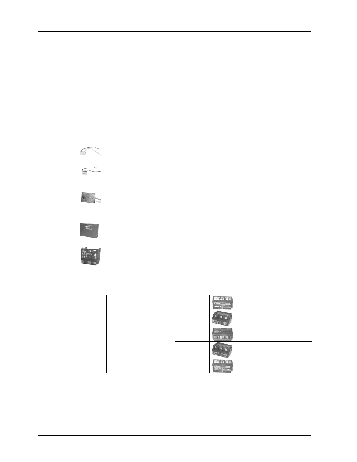
Ordering
Burner control, without plug-in base refer to «Type summary»
Connection accessories for small burner controls refer to Data Sheet N7201
- Plug-in base AGK11...
- Cable holders AGK65..., AGK66, AGK67...
- Cable strain relief elements for AGK67...
Connection accessories for small burner controls refer to Data Sheet N7203
- Plug-in base AGK13...
- Plug-in housing AGK56
- Accessories AGK68
Flame detectors
- Ionization probe supplied by thirds
- UV- flame detectors QRA2... / QRA10... refer to Data Sheet N7712
- Blue-flame detectors QRC1... refer to Data Sheet N7716
RC unit ARC 4 668 9066 0
For the supervision of ionization currents in networks with nonearthed neutral conductor
PTC resistor (AC 230 V) AGK25
To burden terminal 3 (mandatory when using burners with no fan
motor connected to terminal 3)
Auxiliary unit for UV supervision
- Cable length 500 mm AGQ1.1A27
- Cable length 300 mm AGQ1.2A27
- Can be fitted under the plug-in base (refer to «Dimensions»)
Pedestal (empty housing) AGK21
- For increasing the height of the LGB... to that of the LFM... or LFI7...
Service adapter KF8872
- For checking the functioning of the burner controls on the burner plant
- Functional test with signal lamps
- Detector resistance measurement with a jack of 4 mm diameter
Adapters / replacement types
No rewiring required
KF8852
LFI7...
LGB21... with adapter
KF8880
LFM1... ¹)
LFM1...-F ¹)
KF8853-K
LFI7...
LGB22... with adapter
KF8880
LFM1... ¹)
LGB41... with adapter KF8862
LFM1... ¹)
¹) Designed only for ionization
7/22
Building Technologies CC1N7435en
HVAC Products 11.01.2007
Technical data
Mains voltage AC 220 V –15 % ...AC 240 V +10 %
(LGB2... / LGB4...)
AC 230 V –15 % / +10 % (LGB32...!)
AC 100 V –15 % ...AC 110 V +10 %
Mains frequency 50...60 Hz ±6 %
Input current at terminal 12 max. 5 A
within the permissible voltage range
AC 187...264 V or AC 195...253 V
Current rating
- Terminal 3
- Terminals 4, 5 and 7
- Terminals 9 and 10
- Terminal 12
max. 3 A (15 A for max. 0.5 s)
max. 2 A
max. 1 A
max. 5 A
(at Umax. AC 264 V or AC 253 V)
Cable length terminals 8 and 10 20 m at 100 pF / m
Perm. cable lengths
Detector cable laid separately
max. 3 m at 100 pF / m line capacitance
20 m
Power consumption 3 VA
Primary fuse max. 10 A (slow)
Degree of protection IP 40, when built in, with the exception of
the connection area (terminal base)
Mounting position optional
Weight approx. 230 g
Storage
DIN EN 60 721-3-1
Climatic conditions class 1K3
Mechanical conditions class 1M2
Temperature range -20...+60 °C
Humidity < 95 % r.h.
Transport
DIN EN 60 721-3-2
Climatic conditions class 2K3
Mechanical conditions class 2M2
Temperature range -20...+60 °C
Humidity < 95 % r.h.
Operation
DIN EN 60 721-3-3
Climatic conditions class 3K3
Mechanical conditions class 3M2
Temperature range -20...+60 °C
Humidity < 95 % r.h.
Condensation, formation of ice and ingress of water are not permitted!
General unit data
LGB...
Environmental conditions
 Loading...