

Siemens LGA41.153A27, LGA63.191A27, LGA52.171B27, LGA41.173A27, LGA52.150B27 Datasheet
...
CC1N7418en
08.04.2004
Siemens Building Technologies
HVAC Products
7
418
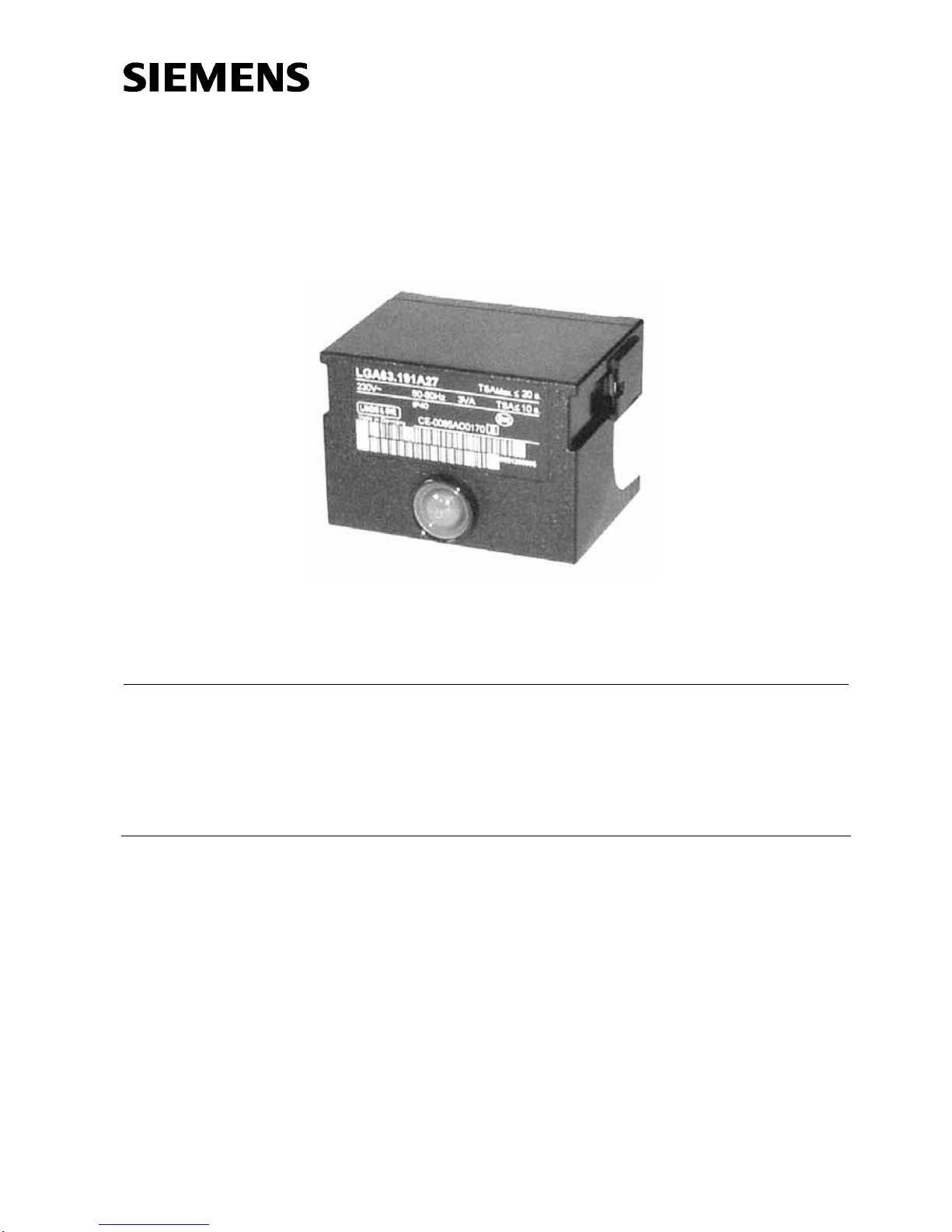
Gas Burner Controls
LGA...
The LGA... are used for the startup and supervision of atmospheric gas burners
of small to medium capacity (without fan) in intermittent operation.
The LGA... and this Data Sheet are intended for use by OEMs which integrate the
gas burner controls in their products.
Use
The flame is supervised with an ionization probe.
Using the appropriate adapters, the LGA... can replace their predecessor types LFI7...
and LFI5... in terms of function and size (refer to «Ordering»).
LGA41.173A27 and LGA52.171B27 are suited for use with direct-fired air heaters.

2/11
Siemens Building Technologies CC1N7418en
HVAC Products 08.04.2004
Warning notes
To avoid injury to persons, damage to property and the environment, the following warning notes should be observed!
Do not open, interfere with or modify the unit.
• All activities (mounting, installation and service work, etc.) must be performed by
qualified staff
• Before performing any wiring changes in the connection area of the LGA..., com-
pletely isolate the burner control from the mains supply (all-polar disconnection)
• Ensure protection against electric shock hazard by providing appropriate protection
for the burner control’s connections terminals
• Check to ensure that wiring is in an orderly state
• Press the lockout reset button / operating button only manually (applying a force of
no more than 60 N), without using any tools or pointed objects
• Fall or shock can adversely affect the safety functions. Such units may not be put
into operation even if they do not exhibit any damage
Mounting notes
• Ensure that the relevant national safety regulations are complied with
• The ionization probe and ignition electrode must be positioned such that the igni-
tion spark cannot arc over to the ionization probe
• The position and polarity of the ignition electrode can adversely affect the magnitude of the flame signal. Reversal of polarity of the ignition transformer’s connections on the primary side usually solves the problem
• Since the burner bars form the earthed counter-electrode, the burner must be adjusted such that the flame is hot and stable and in firm contact with the burner bars.
With pulsating flames or yellow-burning flames resulting from lack of air, a very low
or even no ionization current is generated so that the burner control will initiate
lockout
Installation notes
• To isolate the burner control from the mains supply, use an all-polar switch with a
contact gap of at least 3 mm
• Secure the earthing lug in the terminal base with a metric screw and a lockwasher
or similar
• Switches, fuses, earthing, etc., must be in compliance with local regulations; pri-
mary fuse max. 10 A (slow)
• Make absolut ely certain that life and neutral conductors are correctly connected to
terminals 1 and 2 of the burner control; otherwise, no flame signal will be generated
• Connect the gas pressure switch and other monitoring devices - whose contacts
must be closed from startup to controlled shutdown - in series with «R» and «W»
• If the fully closed position of the main gas valve «BV2» shall be checked on burner
startup, the closed position contact must be included in the loop between terminals
9 and 3. In addition, the connecting links between terminals 9 and 11 and 8 and 3
must be fitted
• During the startup sequence, terminal 6 carries voltage and may not be used as an
auxiliary terminal
• The auxiliary contact of a gas valve for checking the fully closed position must be
included in the loop between terminals 9 and 3
• During the startup sequence, terminals 9 and 6 carry voltage and may not be used
as auxiliary terminals
• Connect the load controller of 2-stage burners to terminal 5 in series with «BV2»
Siting the ionization
probe
Only with LGA41...
Only with LGA52... /
LGA63...
3/11
Siemens Building Technologies CC1N7418en
HVAC Products 08.04.2004
Electrical connection of ionization probe
It is important to achieve practically disturbance- and loss-free signal transmission:
• Never run the detector cable together with other cables
– Line capacitance reduces the magnitude of the flame signal
– Use a separate cable
• Observe the permissible length of the detector cable (refer to «Technical data»)
• The ionization probe is not protected against electric shock hazard
• Locate the ionization probe such that the ignition spark cannot arc over (risk of
electrical overloads)
• Always run the high-voltage ignition cables separate from the unit and other cables
while observing the greatest possible distances
• The insulation resistance between ionization probe and ground must be a minimum
of 50 MΩ, even after a large number of operating hours.
Prerequisite for this is not only high quality heat-resistant insulation of the cable,
but also of the ionization probe itself (ceramic holder!)
• A soiled ionization probe holder offers favorable conditions for surface leakage cur-
rents which reduce the magnitude of the flame signal
• The burner (as the counter-electrode) must be correctly earthed, or else no ioniza-
tion current will flow
Earthing the boiler alone does not suffice!
• The connection diagrams shown apply to burner controls with earthed neutral con-
ductor. In the case of ionization current supervision in networks with nonearthed
neutral conductor, terminal 2 must be connected to the earth conductor via an RC
unit (part no. ARC 4 668 9066 0). In that case, it must be made certain that the
relevant national safety regulations are complied with (e.g. electric shock hazard
protection), since AC 230 V / 50 Hz mains voltage results in a leakage current of
2.7 mA
Commissioning notes
• Prior to commissioning, check to ensure that wiring is in an orderly state
• When commissioning the plant or when doing maintenance work, make the follow-
ing safety checks:
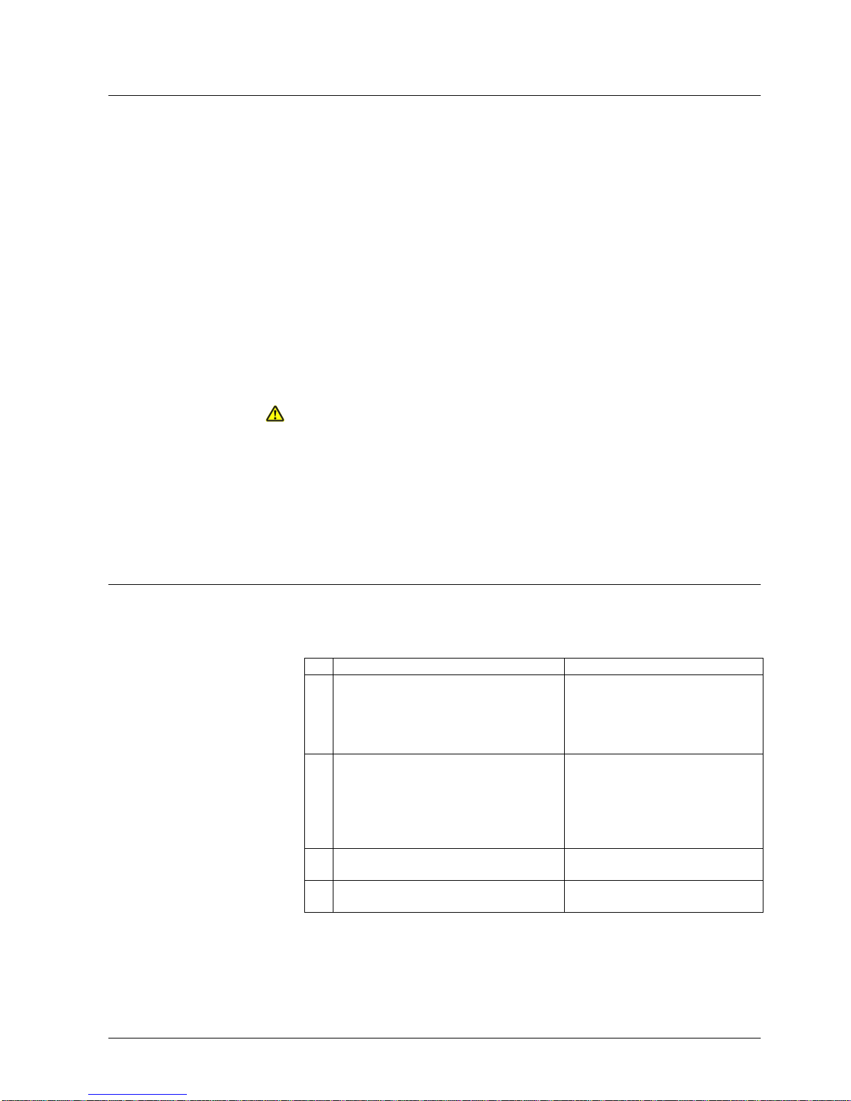
Safety check Anticipated response
a) Burner startup with no flame signal; for
that purpose, open the connection between burner control and ionization
probe prior to burner startup and maintain that status
Lockout at the end of «TSA»
b) Burner operation with simulated loss of
flame during operation; for that purpose,
open the connection between burner
control and ionization probe during
burner operation and maintain that
status
Restart, followed by lockout at the
end of «TSA»
c) No air pressure signal during «t1» (only
with LGA52... / LGA63... with fan)
No startup
d) Air pressure failure during operation
(only with LGA52... / LGA63... with fan)
Shutdown
4/11
Siemens Building Technologies CC1N7418en
HVAC Products 08.04.2004
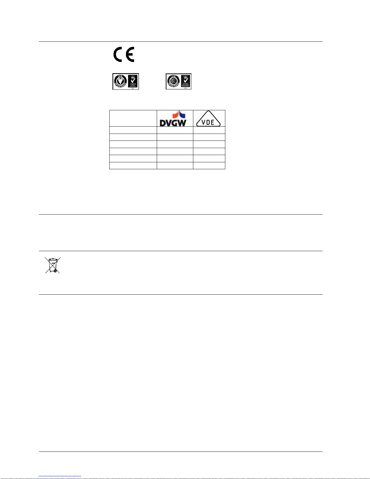
Standards and certificates
Conformity to EEC directives
– Electromagnetic compatibility EMC (immunity)
- Directives for gas-fired appliances
89 / 336 EEC
90 / 396 EEC
ISO 9001: 2000
Cert. 00739
ISO 14001: 1996
Cert. 38233
LGA41.153A27 --- --LGA41.173A27 x x
LGA52.150B17 x --LGA52.150B27 x --LGA52.171B27 x x
LGA63.191A27 x ---
• Identification code to EN 298
- A M C L X N single-stage
- A T C L X N 2-stage
Service notes
• Each time a unit has been replaced, check wiring to ensure that it is in an orderly
state and make the safety checks as indicated in «Commissioning notes»
Disposal notes
The unit contains electrical and electronic components and may not be disposed of together with household waste.
Local and currently valid legislation must be observed.
Mechanical design
The gas burner controls are of plug-in design, suitable for installation in any position on
burners, in control cabinets or on control panels.
The housing is made of impact-proof, heat-resistant plastic and accommodates:
- The thermal sequencing device (ambient temperature-compensated) acting on a
multiple snap action switching system,
- The flame signal amplifier with the flame relay, and
- The lockout warning lamp and lockout reset button (splash-proof)
In the event mains voltage drops below about AC 165 V, an electronic circuit ensures
that the gas burner control will prevent burner startup or – without releasing fuel – lockout will be initiated.
• Undervoltage threshold: AC 178 V ±10 V
• «TSA»: Smaller tolerance band
• Flame signal amplifier: Higher sensitivity, for typical applications with pilot flames
LGA...
Undervoltage detection
Only with
LGA63.191A27
 Loading...