

Siemens LCM-OAVS 570-804PA Installation Instructions Manual
Installation Instructions
Document No. 570-114
October 26, 2016
LCM-OAVS Room Pressurization with,
Two Venturi Air Valves (One Exhaust,
One Supply) and HW Reheat (including
BTU Compensation)
BACnet LCM-OAVS with HW Reheat
and Two Venturi Air Valves — One
Exhaust, One Supply Applications 6750
(RTS) 6756 (BTU)
This controller requires Offboard Air
Module(s) (ordered and shipped
separately
570-804PA
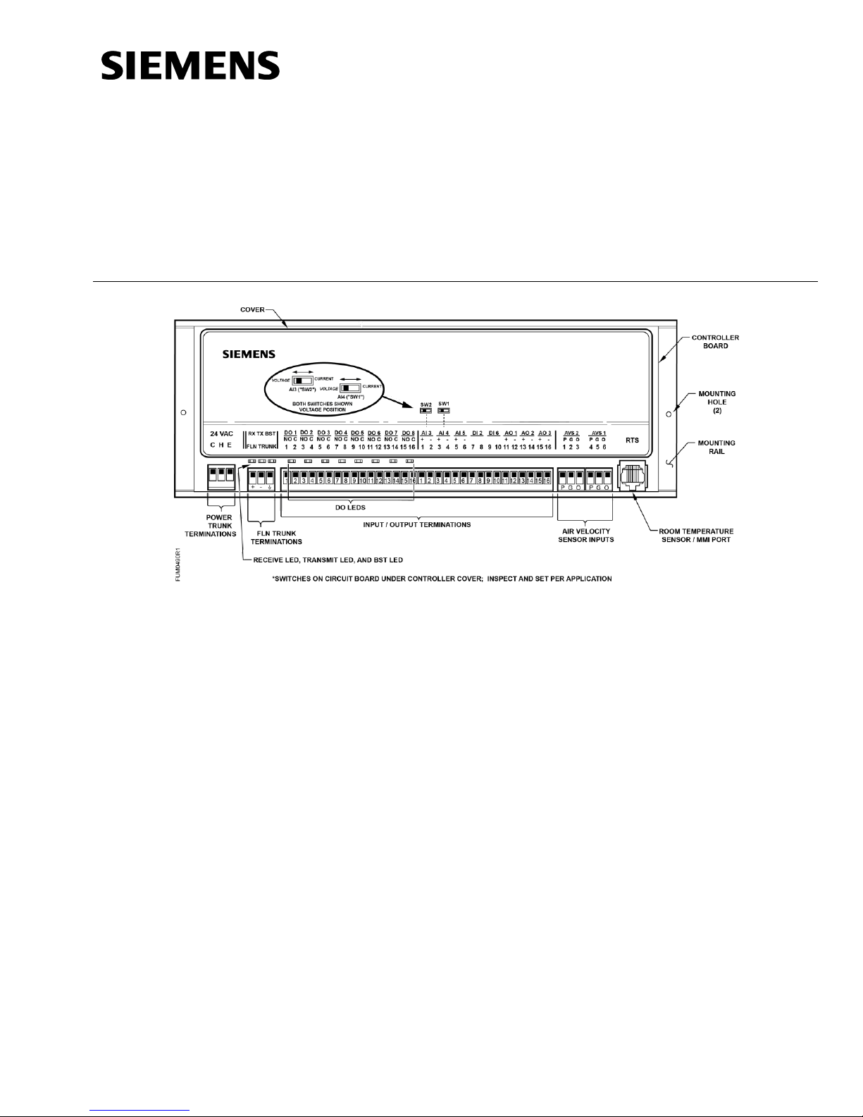
Generic Controller I/O Layout. See Wiring Diagram for application specific details.
Control Applications
6750, 6756
Product Description
The Siemens Venturi Air Valve is a pre-packaged,
easy to install airflow measurement and control
solution. It provides stable and precise airflow
control of room supply, room general exhaust or
fume hood exhaust.
These instructions explain how to field install or
replace the BACnet Laboratory Controller Module
LCM.
This BACnet LCM-OAVS VAV Room Pressurization
Controller with HW Reheat and Two Fast-acting
Venturi Air Valves — One Exhaust, One Supply
features VAV control of a laboratory room with one
supply duct, one exhaust duct, and up to six Fume
Hoods. It uses fast-acting electronic actuators
(shipped separately) to control the supply and
exhaust Venturi air valves.
Item No. 570-114 Rev. CA Page 1 of 8
This controller is built on a BACnet Programmable
TEC (PTEC) platform that supports up to two
Offboard AVS signals; however, Onboard AVS
transducers are not supported. Offboard Air
Module(s) (OAM) house AVS transducers and send
signals to the AVS input(s) on the LCM OAVS
board.
The LCM can operate stand-alone, with a field
panel, or as part of a network.
Product Numbers
See the
Technical Specification Sheet
Configuration and Sizing
section of InfoLink.
Venturi Air Valve for Critical Environments
(149-425) or
in the Critical Environments
Document No. 570-114
Offboard Air Module – two required,
order separately
550-819B
Siemens fast-acting Lab Electronic
Actuator(s) – order and ship separately)
GNP191.1U
CAUTION
Keep the unit in its static-proof bag
until installation.
Otherwise, you run the risk of
damage to the printed circuit board
from electrostatic discharge.
Low cost temporary temperature
sensor, 10K Ω thermistor with
RJ11 (1” long), that enables space
control if the permanent room or
duct sensor is not installed (pack of
25).
540-658P25
Duct Temperature Sensor, NTC
10K Ω Type 2, 3" Probe for
Commissioning only.
QAM1030.008P50
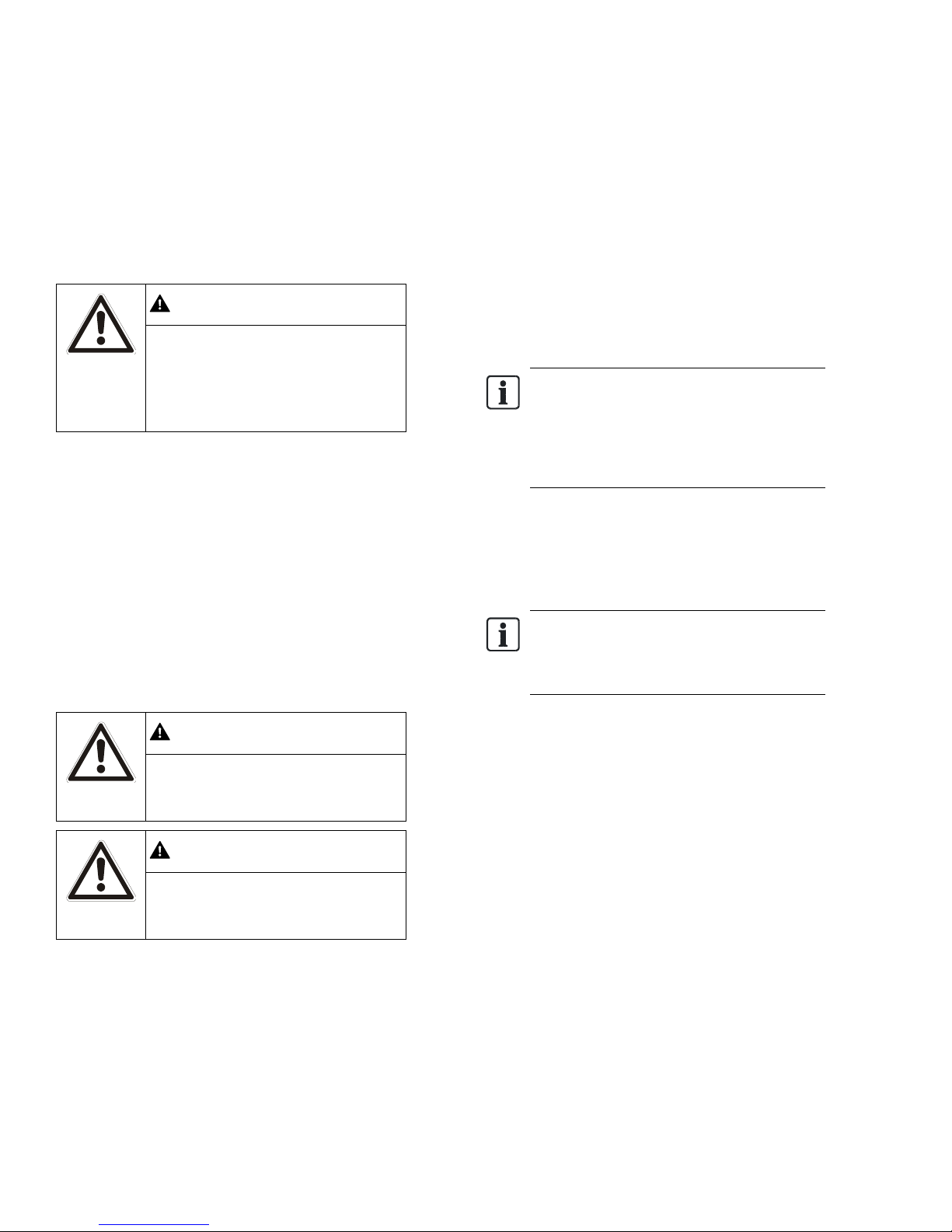
WARNING
Personal injury/loss of life may
occur if you do not follow the
procedures as specified.
CAUTION
Equipment damage or loss of data
may occur if you do not follow the
procedures as specified.
NOTE:
A low-cost temporary RTS (540-658P25)
is available that plugs into the RTS port
on the controller, providing temperature
input and actual space control until a
permanent RTS is installed.
NOTE:
All wiring must conform to national and
local codes and regulations (NEC, CE,
and so on).
Installation Instructions
October 26, 2016
Shipping carton includes a controller assembly, a
mounting rail, and two self-tapping/drilling screws.
Accessories
Prerequisites
Wiring conforms to NEC and local codes and
regulations. For further information, see the
Wiring Guidelines Manual
(Optional)
24 Vac Class 2 power available.
Supply power to the unit is OFF.
Any application specific hardware or devices
Room temperature sensor installed.
installed.
(125-3002).
Warning/Caution Notation
Required Tools and Equipment
Small flat blade screwdriver
3/8-inch open end wrench
Expected Installation Time
30 minutes
Installation Instructions
1. Secure the mounting rail in the controller’s
desired location.
2. Place the ESD wrist strap on your wrist and
attach it to a good earth ground.
3. Remove the controller from the static proof bag
and snap it into place on the mounting rail.
4. If the controller will be used with a field panel,
disconnect the field level network (FLN) trunk
from the field panel.
5. Wire the FLN trunk to the controller. After all
controllers are connected to the FLN, reconnect
the FLN trunk to the field panel.
Needle nose pliers
1/4-inch poly tubing
Page 2 of 8 Siemens Industry, Inc.
Document No. 570-114
CAUTION
DO Wiring – Each DO provides a
Normally Open (NO) terminal and a
Common (C) terminal.
To reduce noise and the potential
for ground loops, both connections
of a 24 Vac load must be wired
directly to the DO terminal on the
controller board.
CAUTION
The fume hood flow module, the
FHC, any 0 to 10 Vdc actuator used
by the LCM, and the LCM cannot
share a single power trunk.
The preferred configuration for
shared power trunks is to use one
trunk for the FFM and FHC and
another trunk for the actuator(s) and
LCM.
8.
For each Fast Acting Lab Electronic Actuator,
verify that the switches are set as shown in
Figure
Switch Settings for the Fast Acting
Lab Electronic Actuator
.
Supply
Exhaust
Switch Settings for the Fast Acting Lab Electronic
Actuator.
CAUTION
This actuator requires a maximum
of 20 VA, 24 Vac source.
DO NOT connect any other nonisolated devices to the transformer
that powers the electronic actuator
or the hot water valve actuator.
9.
Plug the room temperature sensor cable into
the RTS port.
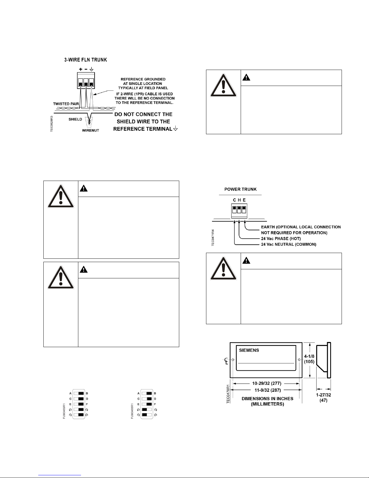
10.
Connect the power trunk. DO NOT apply
power to the controller without first consulting
the specialist.
CAUTION
It is important that the neutral that
supplies the TEC must be earth
grounded at the source of the 24
Vac power.
Possible erratic equipment
operation or damage if neutral is not
grounded.
Installation Instructions
October 26, 2016
6. If the controller requires Offboard Air Modules,
install them now following the appropriate
Installation Instructions (see
7. Connect the point wiring (see
Product Numbers
Wiring Diagram
).
s).
Siemens Industry, Inc. Page 3 of 8
The installation is complete.
Dimensions.
 Loading...