

Page 1
Operating and
installation instructions
Gebruiksaanwijzing en
montagevoorschrift
LC 46254
Page 2
2
ᇖ
03–14
15 – 25
26 – 36
၁ 03–14
nl
pagina 27 – 38
en
ఞ
GAZ
KAASU
GASS
GAZ
page 15 – 26
Abb. 1
ఞ
ELECTR.
ELETT .
EL.
ELEKTR.
ቒཱིঢ়
min. 650
ቒཱིঢ়
min. 550
Page 3
՛
3
ሔ൬
֮ڋഈ
ܸ
ᅽଃ
❑
❑
❑
D
ݝ۳ᅌ
❑
❑
❑
❑
Page 4
4
❑
❑
❑
❑
❑
Page 5
5
!
Page 6
6
❑
❑
0
1
ڋഈְ࠰֮
❑
❑
2
ڋഈְ࠰֮
3
❑
❑
❑
❑
Page 7
❑
7
❑
❑
❑
Page 8
8
❑
❑
❑
❑
❑
❑
❑
❑
❑
❑
Page 9
9
Page 10
10
ቒཱིঢ়60
D
150
150
ቒཱིঢ়
684-1086
136
500
45
280
/
260
ቒཱིঢ়
400
600/700/900/
1000/1
ቒཱིঢ়
460
1200
100
D
Page 11
11
❑
❑
❑
❑
❑
❑
❑
❑
❑
❑
Page 12
12
❑
ቒཱིঢ়
ቒཱིঢ়
600/700/900/
1000/1
100/1200
❑
❑
060 cm
070 cm
090 cm
100 cm
110 cm
120 cm
ఞ ߗఞ
15.0
16.0
17.5
19.0
21.0
23.0
17.0
18.0
19.5
21.0
23.0
25.0
Page 13

13
30
347
36.5
ቒཱིঢ়550 ఞ
ቒཱིঢ়650ఞ
ᄆݿૣ
216
178
400
Page 14

14
3.
1.
2.
Page 15

15
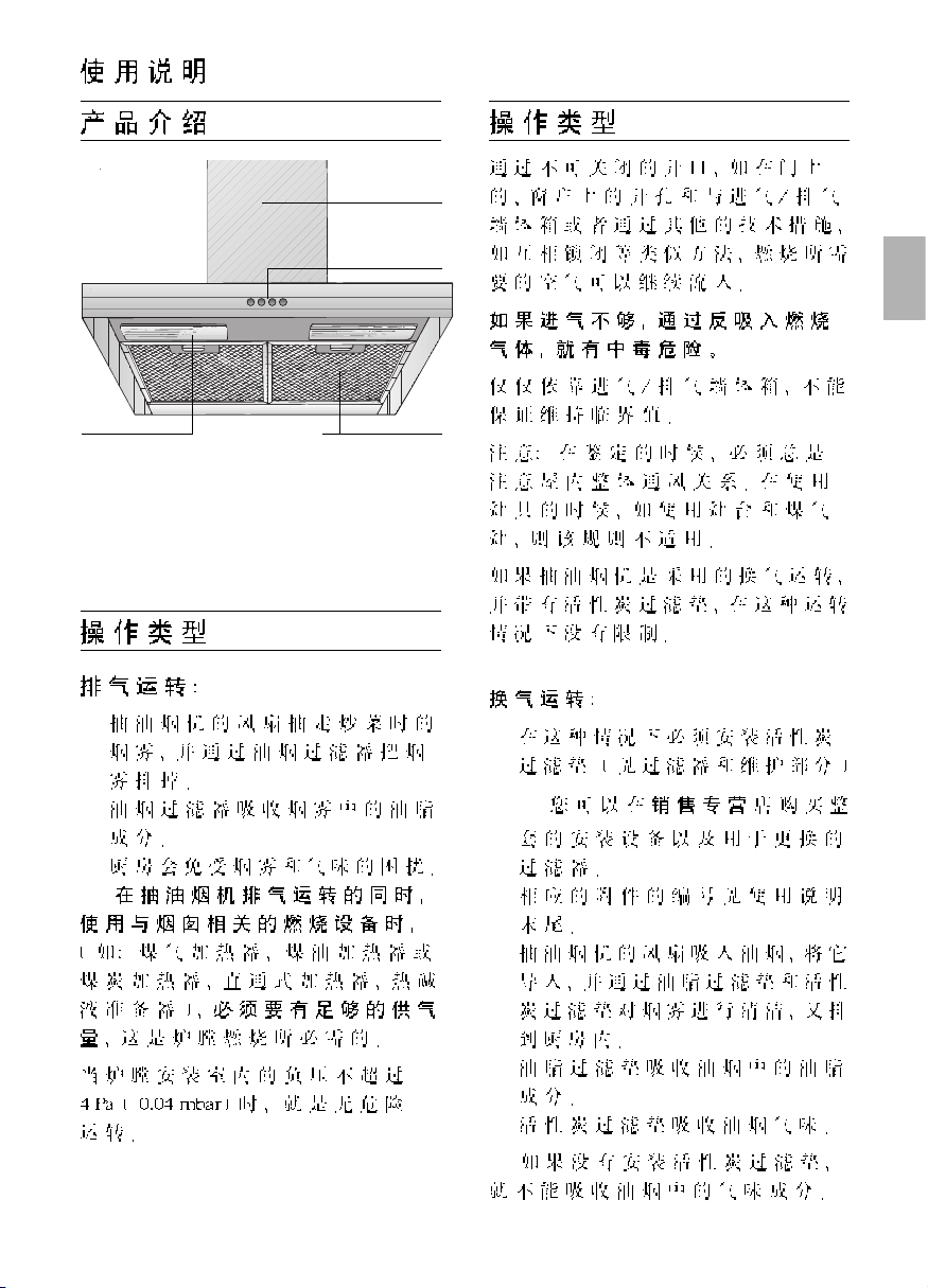
Appliance description
Operating Instructions
Operating modes
Operating modes
Exhaust-air mode:
❑ The extractor-hood fan extracts the kit-
chen vapours and conveys them through
the grease filter into the atmosphere.
❑ The grease filter absorbs the solid
particles in the kitchen vapours.
❑ The kitchen is kept almost free of grease
and odours.
D
When the extractor hood is operated
in exhaust-air mode simultaneously with
a different burner which also makes use
of the same chimney (such as gas, oil or
coal-fired heaters, continuous-flow heaters,
hot-water boilers) care must be taken to
ensure that there is an adequate supply
of fresh air which will be needed by the
burner for combustion.
Safe operation is possible provided that the
underpressure in the room where the
burner is installed does not exceed 4 Pa
(0.04 mbar).
This can be achieved if combustion air can
flow through non-lockable openings, e.g. in
doors, windows and via the airintake/exhaust-air wall box or by other
technical measures, such as reciprocal
interlocking, etc.
If the air intake is inadequate, there is a
risk of poisoning from combustion gases
which are drawn back into the room.
An air-intake/exhaust-air wall box by itself is
no guarantee that the limiting value will not
be exceeded.
Note: When assessing the overall
requirement, the combined ventilation
system for the entire household must be
taken into consideration. This rule does not
apply to the use of cooking appliances,
such as hobs and ovens.
Unrestricted operation is possible if the
extractor hood is used in recirculating mode
– with activated carbon filter.
Circulating-air mode:
❑ An activated carbon filter must be fitted
for this operating mode (see Filters and
maintenance).
The complete installation set and
replacement filters can be obtained from
specialist outlets.
❑ The extractor-hood fan extracts the
kitchen vapours which are purified in the
grease filter and activated carbon filter
and then conveyed back into the
kitchen.
❑ The grease filter absorbs the grease
particles in the kitchen vapours.
❑ The activated carbon filter binds the
odorous substances.
If no activated carbon filter is installed,
it is not possible to bind the odorous
substances in the cooking vapours.
Lighting
Light / fan
switches
Filter grille
Chimney
panelling
Page 16

16
Before using for the first time
If you encounter a problem
If you have any questions or if a fault
occurs, please call Customer Service.
(See list of Customer Service
representatives).
When you call, please quote the following:
E-Nr. FD
Enter the relevant numbers into the box
above. The E-Nr. (product no.) and FD
(production date) are shown on the
nameplate which can be seen inside the
extractor hood after the filter frame has
been detached.
Important notes:
❑ The Instructions for Use apply to several
versions of this appliance. Accordingly,
you may find descriptions of individual
features that do not apply to your
specific appliance.
❑ This extractor hood complies with all
relevant safety regulations.
Repairs should be carried out by
qualified technicians only.
Improper repairs may put the user at
considerable risk.
❑ Before using your appliance for the first
time, please read these Instructions for
Use carefully. They contain important
information concerning your personal
safety as well as on use and care of the
appliance.
❑ Please retain the operating and
installation instructions for a subsequent
owner.
Do not use the appliance if damaged.
The appliance may be connected to the
mains by a qualified technician only.
The appliance is not intended for use by
young children or infirmed persons
without supervision.
Young children should be supervised to
ensure they do not play with the appliance.
If the connecting cable for this
appliance is damaged, the cable must be
replaced by the manufacturer or his customer
service or a similarly qualified person in order
to prevent serious injury to the user.
Dispose of packaging materials
properly (see Installation instructions).
This extractor hood is designed for
domestic use only.
Light bulbs must always be fitted when
the extractor hood is in use.
Defective bulbs should be replaced
immediately to prevent the remaining bulbs
from overloading.
Never operate the extractor hood
without a grease filter.
Overheated fat or oil can easily catch fire.
If you are cooking with fat or oil, e.g. chips,
etc., never leave the cooker unattended.
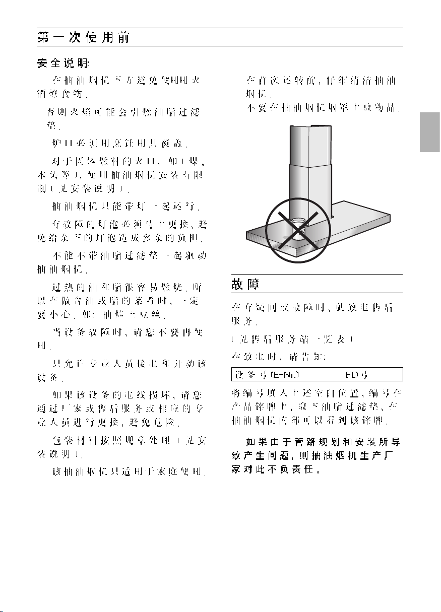
Do not flambé food directly under the
extractor hood.
Risk of grease filter catching fire due
! to flames.
The hotplates must always be covered
with a utensil.
Restrictions apply to the use of the
extractor hood over a solid-fuel burner
(coal, wood, etc.). (See Installation
instructions).
Gas hobs / Gas cookers
Do not use all the gas hotplates
simultaneously for a prolonged period
(max. 15 minutes) at maximum thermal
load, otherwise there is a risk of burns if the
housing surfaces are touched or a risk of
damage to the extractor hood. If the
extractor hood is situated over a gas hob,
operate the hood at maximum setting if
three or more gas hotplates are operated
simultaneously.
Page 17

17
The most effective method of removing
vapours produced during cooking is to:
❑ Switch the ventilator ON
as soon as you begin cooking.
❑ Switch the ventilator OFF
a few minutes after you have finished
cooking.
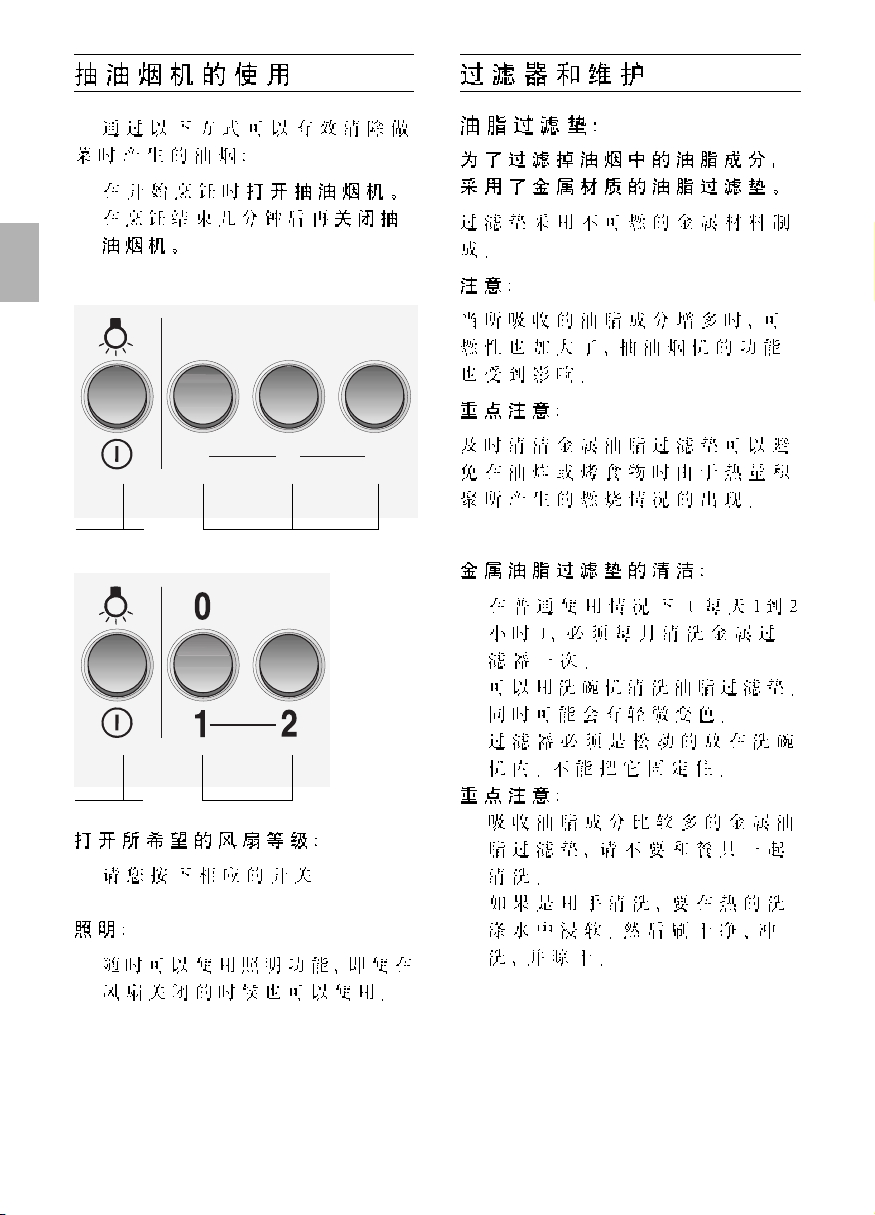
Operating procedure
Setting the required fan speed:
❑ Press the corresponding button.
Lighting:
❑ The light can be switched on at any
time, even though the fan is switched off.
Fan settings
Light
Fan settings
Light
Filters and maintenance
Grease filters:
Metal filters are used to trap the greasy
element of the vapours that develop
during cooking.
The filter mats are made from noncombustible metal.
Caution:
As the filter becomes more and more
saturated with grease, not only does the
risk of it catching fire increase but the
efficiency of the extractor hood can also be
adversely affected.
Important:
By cleaning the metal grease filters at
appropriate intervals, the possibility of them
catching fire as a result of a build-up of heat
such as occurs when deep-fat frying or
roasting is taking place, is reduced.
Cleaning the metal grease filters:
❑ In normal operation (1 to 2 hours daily),
the metal grease filter must be cleaned
after 8 to 10 weeks.
❑ The filters can be cleaned in a dish-
washer. It is however possible that they
will become slightly discoloured.
❑ The filter must be placed loosely, and
NOT wedged, in the dishwasher.
Important:
Metal filters that are saturated with
grease should not be washed together
with other dishes etc.
❑ When cleaning the filters by hand, soak
them in hot soapy water first of all.
Then brush the filters clean, rinse them
thoroughly and leave the water to drain off.
0
1
2
3
Page 18

18
Filters and maintenance
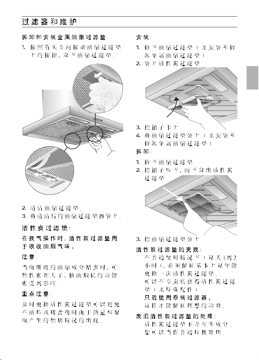
Removing and inserting the metal grease
filters:
1. Press the catch on the grease filters
inwards and fold the filters down.
3. Insert the metal grease filters.
Replacing the activated carbon filter:
❑ During normal operation (1 to 2 hours
per day) the activated carbon filters
should be replaced approximately 1 x
year.
❑ A replacement filter can be obtained
from any authorized dealer.
❑ Use original filters only.
By doing so you will obtain maximum
performance from your extractor hood.
Disposing of the old activated carbon
filter:
❑ There are no pollutants in the activated
carbon filters. They can therefore be
disposed of as part of your normal
domestic refuse.
2. Clean the filters.
3. Insert the clean filters back into the
hood.
Activated carbon filter:
For neutralizing odours in recirculating
mode.
Caution:
As the filter becomes more and more
saturated with grease, there is an increased
risk of fire and the function of the extractor
hood may be impaired.
Important:
Change the activated carbon filter promptly
to prevent the risk of fire from the
accumulation of heat when deep-fat frying
or roasting.
3. Engage the lug.
4. Insert the metal grease filters (see
"Removing and inserting the metal
grease filters").
Removing the filter:
1. Remove the metal filters.
2. Press in the lug and remove the
activated carbon filter.
Inserting the filter:
1. Remove the metal filters (see "Removing
and inserting the metal grease filters").
2. Insert the activated carbon filter.
Page 19

19
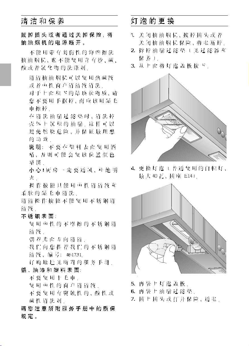
Replacing the light bulbs
1. Switch off the extractor hood and pull
out the mains plug or switch off the
electricity supply at the fuse box.
2. Remove the grease filters (see Filters and
Maintenance).
3. Press down the bulb cover and
disconnect from the light strip.
4. Replace the bulb (standard filament bulb,
max 40 W, E14 bulb holder).
5. Attach the lamp cover again.
6. Re-insert the grease filters.
7. Plug the appliance into the mains or
switch it on at the fuse box.
Cleaning and care
Disconnect the extractor hood from the
electricity supply by pulling out the
mains plug or switching it off at the fuse
box.
❑ At the same time as you clean the
grease filters, clean off any grease from
all accessible parts of the housing. This
significantly reduces the fire hazard and
ensures that the extractor hood
performs as effectively as possible.
❑ Use a hot detergent solution or a mild
window cleaner to clean the canopy of
the extractor hood.
❑ Do not scrape off any dirt that has dried
on but loosen it up with a damp cloth.
❑ Do not use abrasive cleaning agents or
sponges that could cause scratches.
❑ Note: Do not use alcohol (spirit) on
plastic parts, otherwise the surface may
become matt in appearance.
Caution: Ensure that the kitchen is adequately ventilated. Avoid naked flames!
Clean the operating buttons with a mild
soapy solution and a soft, damp cloth only.
Do not use stainless-steel cleaner to clean
the operating buttons.
Stainless steel surfaces:
❑ Use a mild non-abrasive stainless steel
cleaner.
❑ Clean the surface in the same direction
as it has been ground and polished.
Do not use any of the following to clean
stainless steel surfaces: abrasive sponges,
cleaning agents containing sand, soda, acid
or chloride!
Aluminium and plastic surfaces:
❑ Use a soft, non-linting window cloth or
micro-fibre cloth.
❑ Do not use dry cloths.
❑ Use a mild window cleaning agent.
❑ Do not use aggressive, acidic or caustic
cleaners.
❑ Do not use abrasive agents.
Page 20

20
Important information
Installation Instructions:
Additional information concerning gas
cookers:
When installing gas hotplates, comply
with the relevant national statutory
regulations (e.g. in Germany: Technische
Regeln Gasinstallation TRGI).
Always comply with the currently valid
regulations and installation instructions
supplied by the gas appliance
manufacturer.
Only one side of the extractor hood
may be installed next to a high-sided unit
or high wall. Gap at least 50 mm.
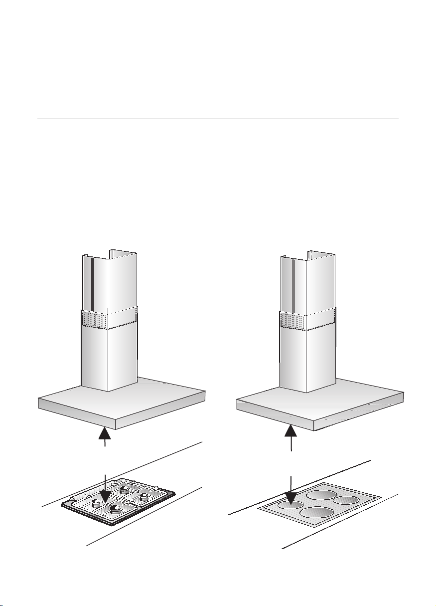
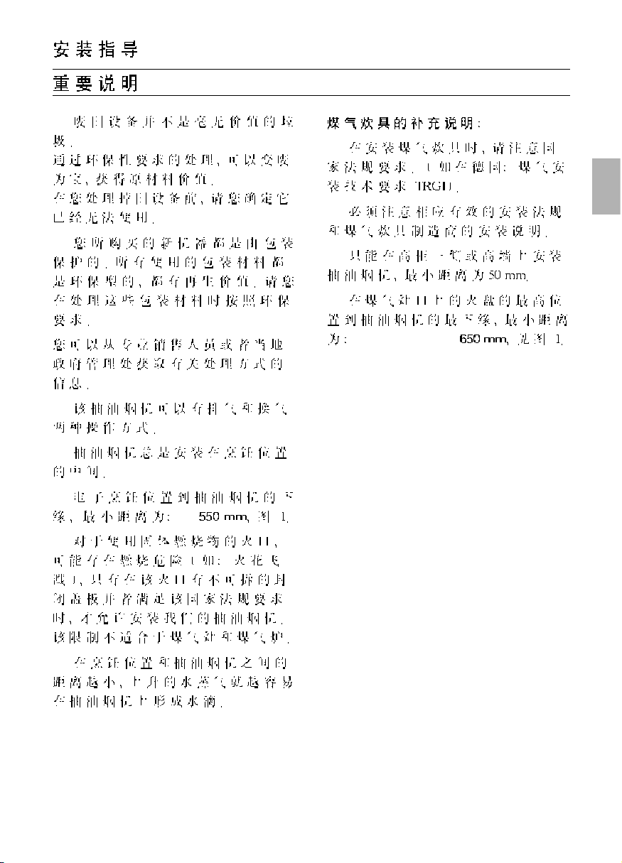
Minimum distance on gas hotplates
between the upper edge of the trivet
and lower edge of the extractor
hood: 650 mm, Fig. 1.
Old appliances are not worthless
rubbish. Valuable raw materials can be
reclaimed by recycling old appliances.
Before disposing of your old appliance,
render it unusable.
You received your new appliance in a
protective shipping carton. All packaging
materials are environmentally friendly and
recyclable. Please contribute to a better
environment by disposing of packaging
materials in an environmentally-friendly
manner.
Please ask your dealer or inquire at your
local authority about current means of
disposal.
The extractor hood can be used in
exhaust air or circulating air mode.
Always mount the extractor hood over
the centre of the hob.
Minimum distance between electric
hob and bottom edge of extractor hood:
550 mm, Fig. 1.
The extractor hood must not be
installed over a solid fuel cooker – a
potential fire hazard (e.g. flying sparks) –
unless the cooker features a closed,
non-removable cover and all national
regulations are observed.
The smaller the gap between the
extractor hood and hotplates, the greater
the likelihood that droplets will form on the
underside of the extractor hood.
Page 21

21
Prior to installation
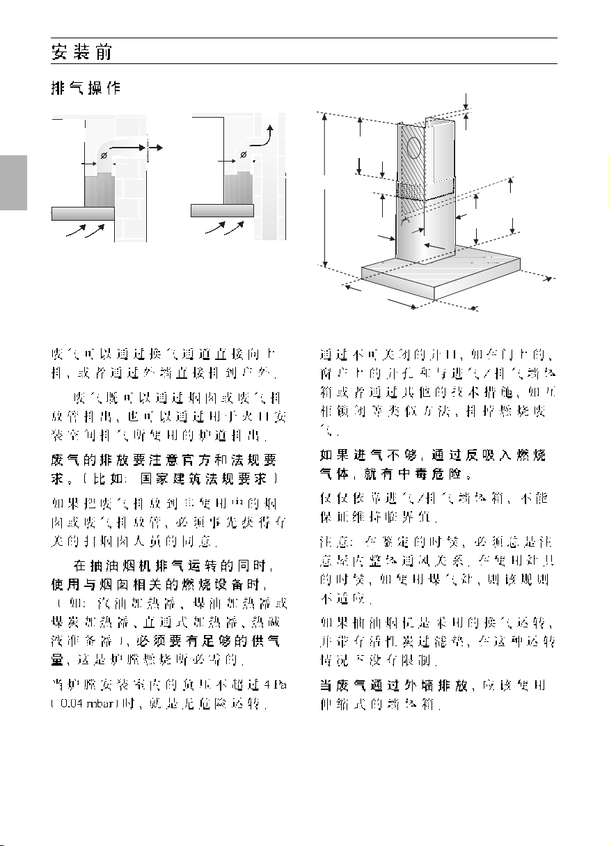
Exhaust-air mode
The exhaust air is discharged upwards
through a ventilation shaft or directly
through the outside wall into the open.
D
Exhaust air should neither be directed
into a smoke or exhaust flue that is
currently used for other purposes, nor into
a shaft that is used for ventilating rooms in
which stoves or fireplaces are also located.
Exhaust air may be discharged in
accordance with official and statutory
regulations only (e.g. national building
regulations).
Local authority regulations must be
observed when discharging air into smoke
or exhaust flues that are not otherwise in
use.
D
When the extractor hood is operated
in exhaust-air mode simultaneously with
a different burner which also makes use
of the same chimney (such as gas, oil or
coal-fired heaters, continuous-flow heaters,
hot-water boilers) care must be taken to
ensure that there is an adequate supply
of fresh air which will be needed by the
burner for combustion.
Safe operation is possible provided that the
underpressure in the room where the
burner is installed does not exceed 4 Pa
(0.04 mbar).
This can be achieved if combustion air can
flow through non-lockable openings, e.g. in
doors, windows and via the airintake/exhaust-air wall box or by other
technical measures, such as reciprocal
interlocking, etc.
If the air intake is inadequate, there is a
risk of poisoning from combustion gases
which are drawn back into the room.
An air-intake/exhaust-air wall box by itself
is no guarantee that the limiting value will
not be exceeded.
Note: When assessing the overall
requirement, the combined ventilation
system for the entire household must be
taken into consideration. This rule does not
apply to the use of cooking appliances,
such as hobs and ovens.
Unrestricted operation is possible if the
extractor hood is used in recirculating
mode – with activated carbon filter.
If the exhaust air is going to be
discharged into the open, a telescopic
wall box should be fitted into the outside
wall.
150
150
mind.60
mind. 45
684-1086
5
136
0
0
mind.
460
mind.
400
260
2
8
0
/1
0
600/700/900/
1000/110
0
20
Page 22

22
Prior to installation
❑ Flat ducts must have an internal cross-
section that equates to that of round
pipes.
There should be no sharp bends.
l 150 mm approx. 177 cm
2
❑ If pipes have different diameters:
Insert sealing strip.
❑ For exhaust-air mode, ensure that
there is an adequate supply of fresh air.
For operating in exhaust-air mode, a
one-way flap should be mounted inside the
extractor hood unless there is already one
fitted in the outlet duct or wall ventilation
box.
If no one-way flap was enclosed with the
hood, it can be obtained from a specialist
retailer.
Attaching the one-way flap:
❑ Insert the two lugs on the one-way flap
into the holes on the air-pipe connector
or air outlet and lock into position.
Before installing the one-way flap,
ensure that the lettering or stamp is on the
outside.
If the exhaust air is going to be
discharged into the open, a telescopic
wall box should be fitted into the outside
wall.
For optimum extractor hood efficiency:
❑ Short, smooth air exhaust pipe.
❑ As few bends in the pipe as possible.
❑ Diameter of pipe to be as large as
possible and no tight bends in pipe.
If long, rough exhaust-air pipes,
many pipe bends or smaller pipe
diameters are used, the air extraction
rate will no longer be at an optimum
level and there will be an increase in
noise.
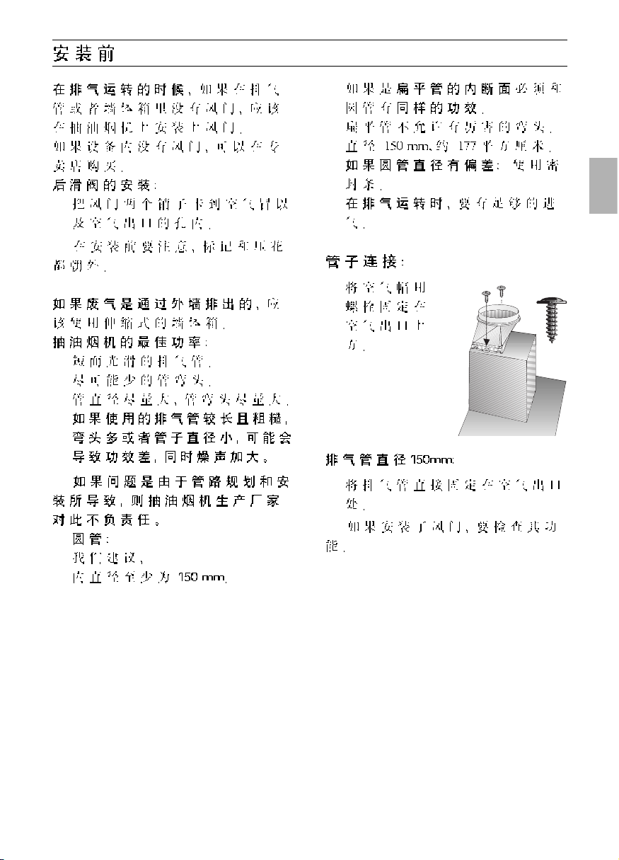
❑ Round pipes:
We recommend
Internal diameter: 150 mm.
Pipe connection
❑ Screw the
enclosed air-pipe
connector over
the air outlet.
150 mm l extraction pipe:
❑ Attach the exhaust-air pipe directly to
the air outlet.
If a one-way flap has been fitted,
conduct a performance test.
Page 23

23
Electrical connection
This is what you have to do:
1.Connect the green and yellow (Earth)
wire to the terminal in the plug marked
‘E’ or with the symbol ( ), or
coloured green or green and yellow.
2.Connect the blue (Neutral) wire to the
terminal in the plug marked ‘N’ or
coloured black.
3.Connect the brown (Live) wire to the
terminal marked ‘L’, or coloured red.
The extractor hood should only be
connected to an earthed socket that has
been installed according to relevant
regulations.
If possible, site the earthed socket directly
behind the chimney panelling.
Electrical data:
Are to be found on the name plate inside
the appliance after removal of the filter
frame.
Before undertaking any repairs,
always disconnect the extractor hood from
the electricity supply.
Length of the connecting cable: 1.30 m.
If it is necessary to wire the extractor
hood directly into the mains:
The extractor hood should only be
connected to the electricity supply by a
properly qualified electrician.
A separator must be installed in the
household circuit. A suitable separator is a
switch that has a contact gap of more than
3 mm and interrupts all poles. Such
devices include circuit breakers and
contactors.
If the connecting cable for this
appliance is damaged, the cable must be
replaced by the manufacturer or his
customer service or a similarly qualified
person in order to prevent serious injury to
the user.
This extractor hood corresponds to EC
regulations concerning RF interference
suppression.
Electrical connection
WARNING: THIS APPLIANCE MUST BE
EARTHED
IMPORTANT: Fitting a Different Plug:
The wires in the mains lead are coloured in
accordance with the following code:
Green and Yellow – Earth
Blue – Neutral
Brown – Live
If you fit your own plug, the colours of
these wires may not correspond with the
identifying marks on the plug terminals.
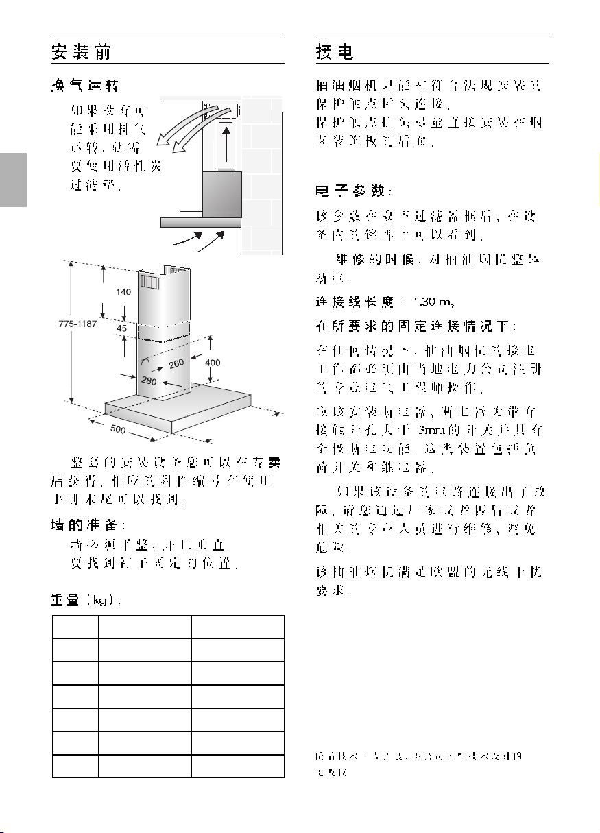
Weight in kg:
Exhaust air Recirculating air
15,0
060 cm
17,0
16,0
070 cm
18,0
17,5
090 cm
19,5
19,0
100 cm
21,0
21,0
110 cm
23,0
23,0
120 cm
25,0
We reserve the right to construction changes within the
context of technical development.
Prior to installation
Circulating-air mode
❑ With activated carbon filter if exhaust-air
mode is not possible.
The complete installation set can be
obtained from specialist outlets.
Preparing the wall
❑ The wall must be flat and perpendicular.
❑ Ensure that the wall is capable of
providing a firm hold for mounting
screws and plugs.
600/700/900/
1000/1100/1200
Page 24

24
Installation
This extractor hood is intended to be
mounted onto the kitchen wall.
1. Remove the grease filter (refer to
Operating Instructions).
2. Draw a line on the wall from the ceiling
to the lower edge of the hood at the
centre of the location where the hood is
going to be mounted.
3. Using the template, mark positions on
the wall for the screws.
Ensure that the minimum distance bet-
ween the hob and the extractor hood is
maintained – 550 mm for an electric hob
and 650 mm for a gas hob. The bottom
edge of the template equates to the lower
edge of the extractor hood.
4. Drill 4 x l 8 mm holes for the extractor
hood and 2 x l 8 mm holes for the
chimney panelling. Insert plugs into the
holes so that they are flush with the wall.
Note: Take into account any special
accessories that are going to be fitted.
5. Attach the 2 enclosed spacers to the
fixing bracket for the flue duct panelling.
Attach the fixing bracket for the
chimney panelling using two hexagon
head cap screws.
6. Screw in the two upper hexagon head
cap screws leaving them extended by
approx. 5 mm.
7. Attach the extractor hood to the
screws.
3
0
178
347
36,5
4
0
0
mind.550 Elektro
mind.650 Gas
2
1
6
ca.5mm
Page 25

25
Installation
08. Screw in the two lower hexagon head
cap screws.
Before the 4 screws are tightened
down, align the extractor hood properly.
11. Remove the protective film from the
two flue ducts.
Take care not to damage the
stainless steel surfaces which are
susceptible to scratches etc.
12. Push both sections of the flue panelling
together (slots in the upper section
must be pointing downwards) and
insert into the opening in the extractor
hood.
Protect the cover panels from
scratches, for example by laying the
template used for marking the wall over
the top edge of the lower section.
09. Connect up the air outlet pipe.
10. Connect the hood to the electricity
supply.
13. Slide out the upper section and attach
it to the mounting brackets at the sides
with two screws.
1.
2.
3.
14. Insert the grease filter (refer to
Operating Instructions).
Page 26

26
Beschrijving van het apparaat
Gebruiksmogelijkheden
Gebruik met luchtafvoer:
❑ De ventilator van de afzuigkap zuigt de
keukenwasem aan en leidt deze via het
vetfilter naar buiten.
❑ Het vetfilter neemt de vaste
bestanddelen van de keukenwasem op.
❑ De keuken blijft in grote mate vrij van vet
en reuk.
D
Als de wasemafzuigkap wordt
gebruikt met luchtafvoer en tegelijkertijd
schoorsteenafhankelijke stookinstallaties worden gebruikt (zoals gas-,
olie- of kolenstookapparaten, geisers,
warmwaterbereidingsapparaten) moet voor
voldoende aanvoer van lucht
worden gezorgd, die nodig is voor de
verbranding.
Gebruik zonder gevaar is mogelijk als de
onderdruk van 4 Pa (0,04 mbar) in de
opstellingsruimte van de stookinstallatie niet
wordt overschreden.
Verlichting
Schakelaars
verlichting en
ventilator
Filterrooster
Schoorsteenafscherming
Gebruiksaanwijzing
Gebruiksmogelijkheden
Dit kan men bereiken wanneer er door
niet-afsluitbare openingen, bijv. in deuren,
ramen en d.m.v. luchtaanvoer-/
luchtafvoersleuven in de muur of door
andere technische maatregelen, zoals
wederzijdse vergrendeling e.d.,
verbrandingslucht kan toestromen.
Wanneer er onvoldoende lucht wordt
aangevoerd, bestaat er vergiftigingsgevaar door teruggezogen verbrandingsgassen.
Alleen een muurkast voor luchttoevoer en
luchtafvoer is geen waarborg voor het
aanhouden van de grenswaarde.
Opmerking: bij de beoordeling moet altijd
de complete ventilatie van de woning in
acht worden genomen. Bij het gebruik van
kookapparatuur, bijvoorbeeld kookplateau
en gasfornuis, wordt deze regel niet
toegepast.
Als de wasemafzuigkap wordt gebruikt met
luchtcirculatie en koolstoffilter is het gebruik
zonder beperking mogelijk.
Gebruik met circulatielucht:
❑ Hiertoe moet een koolstoffilter worden
ingebouwd (zie Filter en onderhoud).
De complete montageset en de
reservefilters zijn verkrijgbaar bij de
vakhandel.
De desbetreffende toebehorennummers
vindt u achterin deze gebruiksaanwijzing.
❑ De ventilator van de wasemafzuigkap
zuigt de keukendamp aan en leidt deze
door het vetfilter en het koolstoffilter
gereinigd terug naar de keuken.
❑ Het vetfilter neemt de vettige
bestand-delen van de keukendamp op.
❑ Het koolstoffilter bindt de reukstoffen.
Als er geen koolstoffilter wordt
gemonteerd, worden de reukstoffen in de
keukendamp niet gebonden.
Page 27

Storingen
Bij eventuele vragen of storingen kunt u
bellen met de klantenservice.
(Zie de lijst met klantenservicecentra).
Geeft u bij het telefoongesprek op:
E-nr. FD
Vul het nummer in de bovenstaande vakjes
in. De nummers staan op het typeplaatje
dat u vindt in de binnenruimte van de
afzuigkap nadat u het filterrooster hebt
verwijderd.
Vóór het eerste gebruik
Belangrijke aanwijzingen:
❑ Deze gebruiksaanwijzing geldt voor
verschillende uitvoeringen van het
apparaat. Het is mogelijk dat er een
aantal kenmerken worden beschreven
die niet van toepassing zijn op uw
apparaat.
❑ Deze afzuigkap voldoet aan de geldende
veiligheidsvoorschriften.
Reparaties mogen uitsluitend worden
uitgevoerd door een vakman.
Door ondeskundige reparaties kunnen
aanzienlijke gevaren voor de
gebruiker ontstaan.
❑ Lees de gebruiksaanwijzing zorgvuldig
voordat u het nieuwe apparaat gebruikt.
Ze bevat belangrijke informatie voor uw
veiligheid en voor het gebruik en het
onderhoud van het apparaat.
❑ Bewaar de gebruiksaanwijzing en het
montagevoorschrift zorgvuldig, eventueel
voor een volgende bezitter van het
apparaat.
De kookzones moeten altijd zijn bedekt
met pannen.
Boven een fornuis voor vaste
brandstoffen (steenkool, hout e.d.) is het
gebruik van de afzuigkap alleen beperkt
toegestaan (zie montagevoorschrift).
Gaskookplaten / gasfornuizen
Gebruik niet alle gaskookzones tegelijk
langdurig (max. 15 minuten) op de hoogste
stand, anders bestaat er kans op
brandwonden bij aanraking van de
oppervlakken van de behuizing en gevaar
van beschadiging van de afzuigkap.
Bij gebruik van de afzuigkap boven een
gaskookplaat waarvan gelijktijdig drie of
meer gaskookzones worden gebruikt, moet
de afzuigkap op de maximumstand worden
gezet.
Indien het apparaat beschadigd is, mag
u het niet in gebruik nemen.
Aansluiting en ingebruikneming mogen
alleen door een vakman worden
uitgevoerd.
Als de aansluitkabel van dit apparaat
beschadigd raakt, moet deze worden
vervangen door de fabrikant, diens
klantenservice of een andere
gekwalificeerde vakman, om gevaren te
voorkomen.
Verpakkingsmateriaal volgens de
voorschriften afvoeren (zie het montagevoorschrift).
Deze afzuigkap mag is uitsluitend
bedoeld voor huishoudelijk gebruik.
Afzuigkap uitsluitend met
ingeschroefde lampen gebruiken.
Defecte lampen dienen onmiddellijk
vervangen te worden om overbelasting van
de overige lampen te voorkomen.
Afzuigkap nooit zonder vetfilter
gebruiken.
Oververhit vet en olie is gemakkelijk
ontvlambaar.
Daarom gerechten met vet of olie, b.v. patates frites, alleen onder toezicht
toebereiden.
Onder de afzuigkap niet flamberen.
Brandgevaar bij het vetfilter door
! opstijgende vlammen.
27
Page 28

28
De keukenwasem wordt op de
doeltreffendste manier verwijderd door:
❑ Inschakelen van de afzuigkap
bij het begin van het koken.
❑ Uitschakelen van de afzuigkap
pas enkele minuten na het einde van het
koken.
Bedienen van de wasemafzuig
kap
Gewenste ventilatorstand instellen:
❑ Druk op de desbetreffende toets.
Verlichting:
❑ De verlichting kan op elk moment
worden gebruikt, ook als de ventilator is
uitgeschakeld.
Ventilatorstanden
Licht
Ventilatorstanden
Licht
Filter en onderhoud
Vetfilters:
Voor de opname van de vettige
bestanddelen van de keukenwasem
worden metalen vetfilters gebruikt.
De filtermatten bestaan uit onbrandbaar
materiaal.
Let op:
Bij toenemende verzadiging met
vethoudende resten neemt de ontvlambaarheid toe en kan de werking van de
wasemafzuigkap nadelig worden beïnvloed.
Belangrijk:
Het op tijd reinigen van de metalen vetfilters
voorkomt brandgevaar dat kan ontstaan
door ophoping van warmte tijdens het
frituren of braden.
Reiniging van de metalen vetfilters:
❑ Bij normaal bedrijf (dagelijks 1 tot 2 uur)
moet de metalen vetfilter na 8 tot 10
weken worden gereinigd.
❑ De filters kunnen worden gereinigd in de
vaatwasmachine. Daarbij is een lichte
verkleuring mogelijk.
Belangrijk:
Zeer verzadigde vetfilters niet samen met
vaatwerk reinigen.
❑ Als de filters met de hand worden
gereinigd, moeten deze eerst in een heet
sopje worden gezet om het vuil los te
weken.
Daarna afborstelen, goed schoonspoelen en laten afdruipen.
0
1
2
3
Page 29

29
Filter en onderhoud
Metalen vetfilters verwijderen en
aanbrengen:
1. Druk de blokkering van de vetfilters in de
richting van de pijl in en klap de vetfilters
naar beneden.
3. Breng de vetfilters aan.
Vervangen van het actieve-koolfilter:
❑ Bij normaal gebruik (dagelijks 1 tot 2 uur)
moeten de filters met actieve kool
ongeveer 1x per jaar worden vervangen.
❑ Het actieve-koolfilter is verkrijgbaar in de
vakhandel (zie Extra toebehoren).
❑ Gebruik alleen originele filters.
Daardoor wordt een optimale werking
gewaarborgd.
Afvoer van het oude actieve-koolfilter:
❑ Actieve-koolfilters bevatten geen
schadelijke stoffen. Ze kunnen daarom
bijvoorbeeld met het huisvuil worden
afgevoerd.
2. Reinig de vetfilters.
3. Breng de gereinigde vetfilters weer aan.
3. Bevestig de lip.
4. Breng de vetfilters aan (zie Metalen
vetfilters verwijderen en aanbrengen)
Verwijderen:
1. Verwijder de vetfilters.
2. Druk op de llip en verwijder het
actieve-koolfilter in benedenwaartse
richting.
Aanbrengen:
1. Verwijder de vetfilters (zie Metalen
vetfilters verwijderen en aanbrengen).
2. Breng het actieve-koolfilter aan.
Koolstoffilter:
Voor het opnemen van de reukstoffen als
de afzuigkap werkt met luchtcirculatie.
Let op:
Bij toenemende verzadiging met
vethoudende resten neemt de ontvlambaarheid toe en kan de werking van de
wasemafzuigkap nadelig worden beïnvloed.
Belangrijk:
Door het koolstoffilter op tijd te vervangen,
voorkomt u brandgevaar dat kan ontstaan
door opeenhoping van warmte tijdens het
frituren of braden.
Page 30

30
Lamp vervangen
1. Schakel de wasemafzuigkap uit en maak
het apparaat stroomloos door de stekker
uit het stopcontact te trekken of de
zekering uit te schakelen.
2. Verwijder de vetfilters (zie Filters en
onderhoud).
3. Verwijder de lampafscherming van
bovenaf uit de lamphouder.
4. Vervang de lamp (in de vakhandel
verkrijgbare gloeilamp, max. 40 watt,
fitting E 14).
5. Breng de afscherming van de lamp weer
aan.
6. Breng de vetfilters weer aan.
7. Herstel de stroomtoevoer door de
stekker in het stopcontact te steken of
de zekering in te schakelen.
Reiniging en onderhoud
Wasemafzuigkap stroomloos maken
door de stekker uit het stopcontact te
trekken of de zekering uit te schakelen.
❑ Als de vetfilters worden gereinigd, moet
vetaanslag van de bereikbare delen van
het huis worden verwijderd. Daardoor
wordt brandgevaar voorkomen en blijft
de optimale werking in stand.
❑ Gebruik voor het reinigen van de
wasemafzuigkap een heet sopje of een
mild schoonmaakmiddel voor het
reinigen van ruiten.
❑ Vastgekoekt vuil niet loskrabben, maar
losweken met een vochtige doek.
❑ Geen schurende middelen of krassende
sponsjes gebruiken.
❑ Let op: alcohol (spiritus) niet gebruiken
op kunststof oppervlakken, er kunnen
doffe plekken ontstaan.
Voorzichtig: keuken voldoende
ventileren, geen open vuur gebruiken.
De bedieningstoetsen alleen reinigen
met een mild afwasmiddel en een zachte,
vochtige doek.
Geen edelstaalreiniger gebruiken voor de
bedieningstoetsen.
Edelstalen oppervlakken:
❑ Gebruik een milde, niet-schurende
edelstaalreiniger.
❑ Reinig alleen in de slijprichting.
Edelstalen oppervlakken niet met
krassende sponsjes en niet met zand-,
soda-, zuur- of chloridehoudende
poetsmiddelen reinigen.
Aluminium en kunststof oppervlakken:
❑ Gebruik een zachte, niet-pluizende zeem
of microvezeldoek.
❑ Geen droge doeken gebruiken.
❑ Gebruik een mild glasreinigingsmiddel.
❑ Gebruik geen agressieve, zuur- of
looghoudende reinigingsmiddelen.
❑ Gebruik geen schurende middelen.
Page 31

31
Belangrijke voorschriften
Montagevoorschrift:
Extra voorschriften bij gaskookapparatuur:
Bij de montage van gaskookzones
moeten de geldende wettelijke nationale
voorschriften (bijv. in Duitsland: Technische
regels gasinstallatie TRGI) in acht worden
genomen.
De geldende inbouwvoorschriften en
de aanwijzingen van de fabrikant van het
gasfornuis moeten in acht worden
genomen.
Slechts aan één zijde van de
wasemafzuigkap mag zich na de inbouw
een hoge kast of hoge wand bevinden.
Afstand minstens 50 mm.
Bij gaskookzones bedraagt de
minimumafstand tussen de bovenkant van
de pandrager en de onderkant van de
afzuigkap: 650 mm, afb. 1.
Oude apparaten zijn geen waardeloos
afval. Door een milieubewuste afvoer
kunnen waardevolle materialen opnieuw
worden gebruikt.
Maak het oude apparaat onbruikbaar
voordat u het afvoert.
Uw nieuwe apparaat wordt tijdens het
vervoer beschermd door de verpakking.
Alle gebruikte materialen zijn milieuvriendelijk en kunnen opnieuw worden
gebruikt. Lever uw bijdrage door de
verpakking milieubewust af te voeren.
Informeer bij uw vakhandel of bij de
gemeente naar de beste manier om uw
oude apparaat en de verpakking af te
voeren.
De wasemafzuigkap is geschikt voor
gebruik met luchtafvoer of met luchtcirculatie.
De wasemafzuigkap altijd boven het
midden van het fornuis aanbrengen.
Minimumafstand tussen elektrische
kookzones en de onderkant van de
wasemafzuigkap: 550 mm, afb. 1.
Boven een fornuis voor vaste
brandstoffen waarvan brandgevaar kan
uitgaan (bijvoorbeeld door vonken) is de
montage van de wasemafzuigkap alleen
toegestaan als het fornuis een gesloten,
niet verwijderbare afscherming heeft en
de voor het desbetreffende land geldende
voorschriften in acht worden genomen.
Deze beperking geldt niet voor
gasfornuizen en gasplateaus.
Hoe kleiner de afstand tussen wase-
mafzuigkap en branders is, hoe groter de
mogelijkheid is dat zich door opstijgende
waterdamp onder aan de wasemafzuigkap
druppels kunnen vormen.
Page 32

32
Voor de montage
Afzuigkap met luchtafvoer
De afvoerlucht wordt via een afvoerschacht
naar boven of rechtstreeks door de
buitenmuur naar buiten geleid.
D
De afvoerlucht mag niet worden
afgevoerd via een in gebruik verkerende
rook- of afvoergasschoorsteen of via een
schacht die dient voor de ventilatie van
ruimten waarin stookinstallaties zijn
opgesteld.
Bij de afvoer van afvoerlucht moeten de
officiële en wettelijke voorschriften (bijv.
nationale bouwvoorschriften) worden
nageleefd.
Als de lucht wordt afgevoerd via een in
gebruik verkerende rook- of afvoergasschoorsteen moet de toestemming van de
bevoegde instantie worden verkregen.
D
Als de wasemafzuigkap wordt
gebruikt met luchtafvoer en tegelijkertijd
schoorsteenafhankelijke stookinstallaties worden gebruikt (zoals gas-,
olie- of kolenstookapparaten, geisers,
warmwaterbereidingsapparaten) moet
voor voldoende aanvoer van lucht
worden gezorgd, die nodig is voor de
verbranding.
Gebruik zonder gevaar is mogelijk als de
onderdruk van 4 Pa (0,04 mbar) in de
opstellingsruimte van de stookinstallatie
niet wordt overschreden.
Dit kan men bereiken wanneer er door
niet-afsluitbare openingen, bijv. in deuren,
ramen en d.m.v. luchtaanvoer-/
luchtafvoersleuven in de muur of door
andere technische maatregelen, zoals
wederzijdse vergrendeling e.d.,
verbrandingslucht kan toestromen.
Wanneer er onvoldoende lucht wordt
aangevoerd, bestaat er vergiftigingsgevaar door teruggezogen verbrandingsgassen.
Alleen een muurkast voor luchttoevoer en
luchtafvoer is geen waarborg voor het
aanhouden van de grenswaarde.
Opmerking: bij de beoordeling moet altijd
de complete ventilatie van de woning in
acht worden genomen. Bij het gebruik van
kookapparatuur, bijvoorbeeld kookplateau
en gasfornuis, wordt deze regel niet
toegepast.
Als de wasemafzuigkap wordt gebruikt met
luchtcirculatie en actieve-koolfilter is het
gebruik zonder beperking mogelijk.
Als de afvoerlucht door de buitenmuur
wordt geleid, moet een telescoop-muur-
kast worden gebruikt.
150
150
mind.60
mind. 45
684-1086
5
136
0
0
mind.
460
mind.
400
260
2
8
0
/1
0
600/700/900/
1000/110
0
20
Page 33

33
Voor de montage
❑ Platte kanalen moeten een gelijk-
waardige inwendige diameter als
ronde buizen hebben.
Ze dienen geen scherpe bochten te
hebben.
l 150 mm ca. 177 cm
2
❑ Bij afwijkende buisdiameters:
dichtstrips gebruiken.
❑ Bij gebruik van de wasemafzuigkap
met luchtafvoer moet voor voldoende
luchttoevoer worden gezorgd.
Bij gebruik met luchtafvoer moet in de
wasemafzuigkap een terugsklep worden
ingebouwd, als deze niet in de afvoerbuis
of in de muurkast aanwezig is.
Als er geen terugslagklep met het apparaat
wordt meegeleverd, kan deze in de
vakhandel worden verkregen.
Monteren van de terugslagklep:
❑ De twee pennen van de terugslagklep in
de gaten van het afvoerluchtaansluitstuk
of van de luchtafvoeropening steken.
Voor de montage controleren of het
opschrift/stempel zich aan de buitenkant
bevindt.
Als de afvoerlucht door de buitenmuur
wordt geleid, moet een telescoop-muur-
kast worden gebruikt.
Optimaal vermogen van de wasemafzuigkap:
❑ Korte, gladde luchtafvoerpijp.
❑ Zo min mogelijk bochten.
❑ Zo groot mogelijke buisdiameter en
grote bochten.
Gebruik van lange, ruwe luchtafvoerbuizen, veel buisbochten of kleine
buisdiameters vermindert de
afzuigcapaciteit en veroorzaakt
bovendien hardere geluiden.
❑ Ronde buizen:
wij adviseren
een inwendige diameter van minstens
150 mm.
Buisaansluiting
❑ Het bijgevoegde
luchtafvoeraansluitstuk vastschroeven
op de luchtafvoeropening.
Luchtafvoerbuis l 150 mm:
❑ Luchtafvoerbuis rechtstreeks op de
luchtafvoeropening bevestigen.
Als er een terugsklep is gemonteerd,
controleren of deze goed werkt.
Page 34

34
Elektrische aansluiting
De wasemafzuigkap mag alleen worden
aangesloten aan een volgens de voorschriften geïnstalleerd, geaard stopcontact.
Het geaarde stopcontact moet indien
mogelijk vlak achter de schoorsteenafscherming worden aangebracht.
Elektrische gegevens:
staan op het typeplaatje in de binnenruimte
van het apparaat vermeld en zijn zichtbaar
als het filterframe wordt afgenomen.
Bij reparaties moet de wasemafzuig-
kap altijd stroomloos worden gemaakt.
Lengte van de aansluitkabel: 1,30 m.
Als vaste aansluiting nodig is:
De wasemafzuigkap mag uitsluitend door
een erkende installateur worden
aangesloten.
In de installatie moet een scheidingsvoorziening worden aangebracht. Als
scheidingsvoorzieningen gelden
schakelaars met een contactopening van
meer dan 3 mm en uitschakeling met alle
polen. Daarbij horen aardlekschakelaars en
veiligheidsschakelaars.
Als de elektriciteitskabel van het
apparaat beschadigd raakt, moet deze
worden vervangen door de klantenservice
van de fabrikant of door een gekwalificeerd
vakman, om gevaren te voorkomen.
Deze wasemafzuigkap voldoet aan de EGbepalingen voor radio-ontstoring.
Gewicht in kg:
Constructiewijzigingen in het kader van technische
verbeteringen voorbehouden.
Voor de montage
De complete montageset is
verkrijgbaar bij de vakhandel.
De desbetreffende toebehorennummers
vindt u achterin deze gebruiksaanwijzing.
Voorbereiden van de muur
❑ De muur moet vlak en loodrecht zijn.
❑ Pluggen moet stevig kunnen worden
bevestigd.
Gebruik met circulatielucht
❑ Met een
koolstoffilter,
indien gebruik met
afvoerlucht niet
mogelijk is.
600/700/900
Luchtavoer Luchtcirculatie
15,0
060 cm
17,0
16,0
070 cm
18,0
17,5
090 cm
19,5
19,0
100 cm
21,0
21,0
110 cm
23,0
23,0
120 cm
25,0
Page 35

35
Inbouwen
De wasemafzuigkap is voorzien voor
montage aan de keukenmuur.
1. Vetfilter verwijderen (zie de gebruiks-
aanwijzing).
2. Van het plafond tot aan de onderkant
van de wasemafzuigkap een middellijn
op de muur aftekenen.
3. Met behulp van het sjabloon de posities
voor de schroeven markeren op de
muur.
Minimumafstand in acht nemen van
550 mm tussen wasemafzuigkap en
kookzones van elektrisch fornuis en van
650 mm tussen wasemafzuigkap en
branders van gasfornuis. De onderste rand
van het sjabloon duidt de onderste rand
van de wasemafzuigkap aan.
4. 4 gaten voor de wasemafzuigkap en
twee gaten voor de afscherming van de
schoorsteen l 8 mm boren en pluggen
volledig in de muur duwen.
Opmerking: let op eventueel te monteren
extra toebehoren.
5. Klik de twee meegeleverde
afstandhouders vast in de
bevestigingshaak voor het schoorsteenafschermstuk.
De bevestigingshaak voor het schoorsteenafschermstuk vastschroeven met 2
zeskantschroeven.
6. De twee bovenste zeskantschroeven
vastdraaien tot ze nog ca. 5 mm
uitsteken.
7. Wasemafzuigkap aan de schroeven
hangen.
3
0
178
347
36,5
4
0
0
mind.550 Elektro
mind.650 Gas
2
1
6
ca.5mm
Page 36

36
Inbouwen
08. De twee onderste zeskantschroeven
vastdraaien.
Voordat de vier schroeven worden
vastgedraaid, moet de wasemafzuigkap
op de juiste plaats worden gebracht.
11. Beschermfolie van beide
schoorsteenafschermstukken
verwijderen.
Voorkom beschadiging van de
kwetsbare edelstalen oppervlakken.
12. De beide delen van de schoorsteenaf-
scherming in elkaar schuiven
(openingen op het bovenste
telescoopdeel naar beneden) en in de
uitsparing op de wasemafzuigkap
plaatsen.
Voorkom beschadiging bij het in
elkaar schuiven door bijvoorbeeld het
montagesjabloon ter bescherming over
de rand van de onderste schoorsteenafscherming te leggen.
09. Buisverbinding tot stand brengen.
10. Elektrische verbinding tot stand
brengen.
13. Het bovenste deel omhoog tillen en
met twee schroeven opzij op de
bevestigingshaak schroeven.
1.
2.
3.
14. Vetfilter weer aanbrengen (zie de
gebruiksaanwijzing).
Page 37

37
Notes
Page 38

38
Notes
Page 39

39
Notities
Page 40

9000 052 760
Printed in Germany 0205 Es.
 Loading...