

Siemens KION-i Service manual
KION / KION-i anesthesia workst ation
Service Manual
E382 E392E 061 01 02 02

Notes KION / KION-i
Notes
Siemens-Elema AB
E382 E392E 061 01 02 02

KION / KION-i Important
Contents
Contents
1. Important.......................................................................................................
2. Introduction ..................................................................................................
3. Description of functions.............................................................................
4. Disassembling and assembling ...............................................................
5. Service procedures .....................................................................................
1
2
3
4
5
6. Troubleshooting...........................................................................................
7. Preventive maintenance ............................................................................
8. Index...............................................................................................................
9. Diagrams.......................................................................................................
6
7
8
9
E382 E392E 061 01 02 02
Siemens-Elema AB
1 - 1
Important KION / KION-i
Important
General
• Service documentation for the KION™ / KION-i™
1
anesthesia workstation consists of:
– Operating Manual. The Operating Manual is an
indispensable complement to the Service
Manual for proper servicing.
– Service Manual
– Installation Instructions
– Spare Parts information
– Documentation for the KION / KION-i Monitor.
– Documentation for all optional equipment
included in the KION / KION-i workstation.
• The following conventions are used throughout
this Service Manual:
– KION represents KION anesthesia workstation.
– KION-i represents KION-i anesthesia
workstation.
• The information in this Service Manual is based
on:
– KION version 7.x.
– KION-i version 10.x.
The information in this Service Manual is valid for
both versions unless otherwise stated.
• Serial number of the unit is found on a label
attached by the mains power inlet.
• A system version label is found by the mains
power inlet. Make sure that the version of the
Operating Manual corresponds to this system
version.
Text inside a box is used to highlight important
information.
• In addition to the Important information given
here and in the related documents (e. g. in the
Operating Manual), always pay attention to
applicable local and national regulations.
• Responsibility for the safe functioning of the
equipment reverts to the owner or user in all
cases in which service or repair has been done by
a non-professional or by persons who are not
employed by or authorized by Siemens, and
when the equipment is used for other than its
intended purpose.
Symbols used in this manual
• ESD sensitive components. When
handling ESD-sensitive devices,
established procedures must be
observed to prevent damage.
• Special waste. Discard disposable,
replaced and left-over parts in accordance with appropriate industrial and
environmental standards.
• Recycling. Recycle if possible.
Recycling facilities may not be
available in all areas.
• Technical training. Refers to the
Technical training supplied by
Siemens.
• Service contract. Refers to the
Service contract supplied by
Siemens.
Hazard notices
• Before disassembling or assembling, make sure
that:
– Gas supply is disconnected.
– Mains power cable is disconnected.
– Power switch is set to Off. If the power switch
is set in any other position, the internal battery
will supply power to the PC boards.
– The internal battery is disconnected when the
power section is open.
– All gas conveying parts are cleaned according
to instructions in the KION / KION-i – Operating
Manual, chapter Routine cleaning.
• With power supply connected to the KION /
KION-i workstation, there are energized electrical
components inside the unit. All personnel must
exercise extreme caution if fault tracing or
adjustments are performed with power supply
connected and with user interface and patient
unit covers removed.
Installation
• Only personnel trained and authorized
by Siemens shall be permitted to
install the KION / KION-i workstation.
The installation and handing-over
procedures are described in the
”Installation Instructions”.
1 - 2
Siemens-Elema AB
E382 E392E 061 01 02 02
KION / KION-i Important
Important
Calibration and Functional check
• After any installation, maintenance or service
intervention in KION / KION-i workstation,
perform a ”Calibration” and a ”Function check”
according to instructions in the KION / KION-i –
Operating Manual.
Service
• The KION / KION-i workstation must
be serviced at regular intervals by
personnel trained and authorized by
Siemens. Any maintenance or service
must be noted in a log book provided.
• It is recommended that maintenance
and service is done as a part of a
service contract with Siemens.
• Preventive maintenance must be performed
every:
– Six months. This corresponds to approx. 1.000
hours of operation calculated as operating time
of 40 hours a week during six months. Details
are found in the Operating Manual.
– Twelve months or every 3000 hours of
operation whichever comes first. Details are
found in this Service Manual, chapter
”Preventive maintenance”.
– Three years. The internal battery shall be
replaced every three years according to
instructions in this Service Manual, chapter
”Preventive maintenance”.
• Worn-out batteries must be recycled or
disposed of properly according to local
regulations. Recycle facilities may not
be available in all areas.
• Batteries must not be disposed of with
ordinary waste. Discard disposable,
replaced and left-over parts in accordance with appropriate industrial and
environmental standards.
• When handling ESD-sensitive devices,
established procedures must be
observed to prevent damage.
To the responsible service personnel
• The contents of this document are not binding.
If any significant difference is found between the
product and this document, please contact
Siemens for further information.
• We reserve the right to modify products without
amending this document or advising the user.
• Only personnel trained and authorized
by Siemens shall be permitted to
perform service or repair the KION /
KION-i workstation. Only Siemens
genuine spare parts must be used.
PC boards (spare parts) must always be kept in a
package for sensitive electronic devices. Siemens
will not otherwise assume responsibility for the
materials used, the work performed or any
possible consequences of same.
• The device complies to standards and requirements as stated in the KION / KION-i workstation
– Operating Manual.
1
E382 E392E 061 01 02 02
Siemens-Elema AB
1 - 3

Important KION / KION-i
Notes
1
1 - 4
Siemens-Elema AB
E382 E392E 061 01 02 02

KION / KION-i Introduction
Only personnel trained and authorized
by Siemens shall be permitted to
perform installation, service or
maintenance of the KION / KION-i
workstation.
Make sure to prepare the KION / KION-i
workstation properly before disassembling and
assembling. Refer to section ”Hazard notices” in
chapter ”Important”.
Any service or maintenance must be noted in a
log book.
Discard disposable, replaced and left-over parts in
accordance with appropriate industrial and
environmental standards.
After any installation, maintenance or service
intervention in the KION / KION-i, perform a
”Calibration” and a ”Function check”.
Refer to the ”KION / KION-i anesthesia
workstation – Operating Manual” for details.
2. Introduction
Main units .......................................................... 2 - 2
Battery drawer................................................ 2 - 3
Pneumatic section .......................................... 2 - 4
Vaporizer section ............................................ 2 - 5
Patient unit ..................................................... 2 - 6
User interface ................................................. 2 - 7
Electronic structure ........................................... 2 - 8
General ........................................................... 2 - 8
Internal communication.................................. 2 - 9
2
E382 E392E 061 01 02 02 Siemens-Elema AB
2 - 1
Introduction KION / KION-i
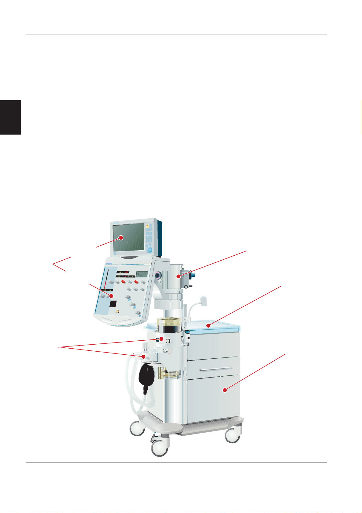
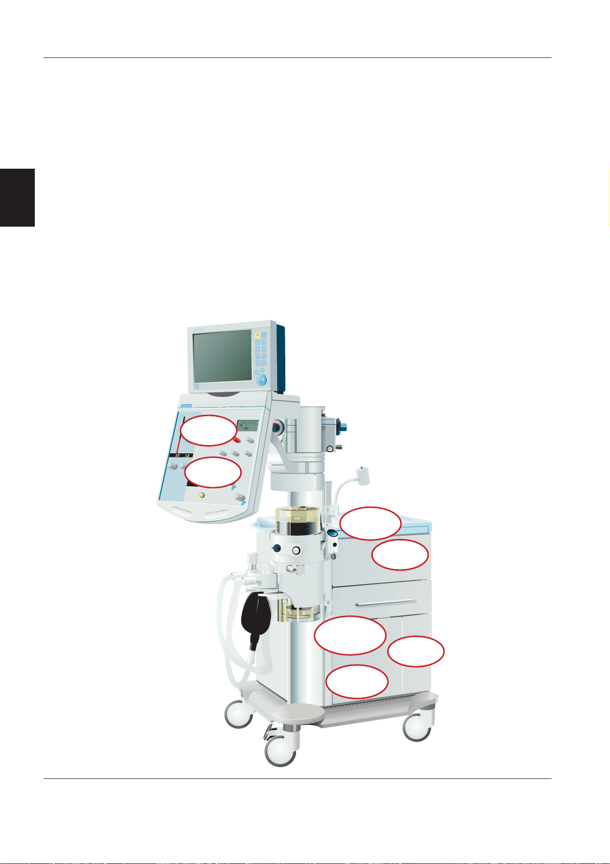
Main units
The KION / KION-i workstation can be divided into
the following functional main units:
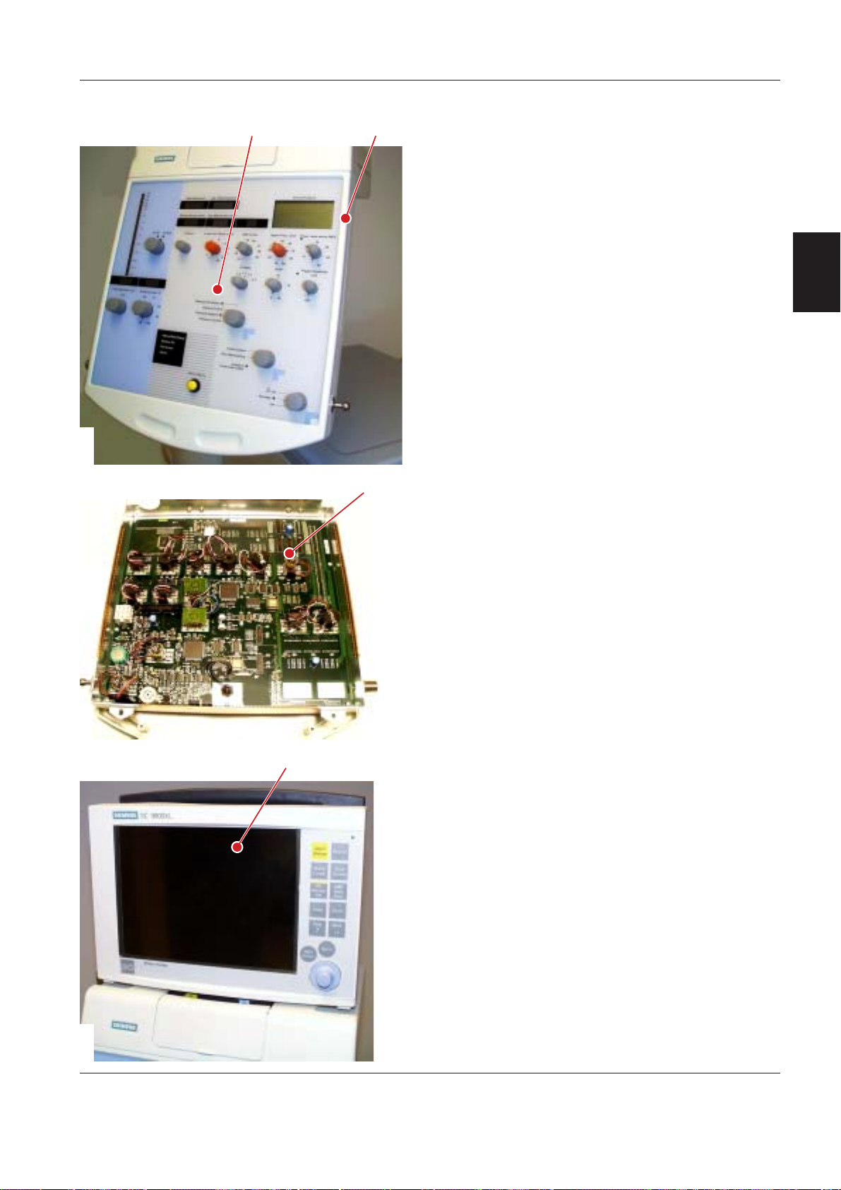
• User interface, i. e. the Control panel and the KION
Monitor. The Monitor is a Siemens patient monitor
(SC 7000, SC 9000 or SC 9000XL) used with the
KION / KION-i workstation.
• Battery drawer
2
• Pneumatic section
• Vaporizer section
• Patient unit.
All these main units are incorporated in or attached to
the cart which is the main body of the system.
The following optional equipment can also be
incorporated in the KION / KION-i workstation:
• DuoView™ overflow screen
• Built-in multigas analyzer
– KION MultiGas 2000
– KION MultiGas+
• O2 Monitoring MiniOX
• Isolation transformer
• Backup gas supply manifold
• Suction equipment
• Auxiliary O
• Gas evacuation
• Accessory and Monitor shelfs
• Medside Data Station for KION.
Functional descriptions, as well as service and
maintenance procedures for these optional
equipments, can be found in this Service Manual. For
Installation Instructions, refer to separate documents.
supply
2
User
interface
Patient unit
KION
Monitor
Control
panel
Vaporizer section
Pneumatic section
Battery drawer
Siemens-Elema AB
E382 E392E 061 01 02 022 - 2
KION / KION-i Introduction
KN9001
@
6;9H<
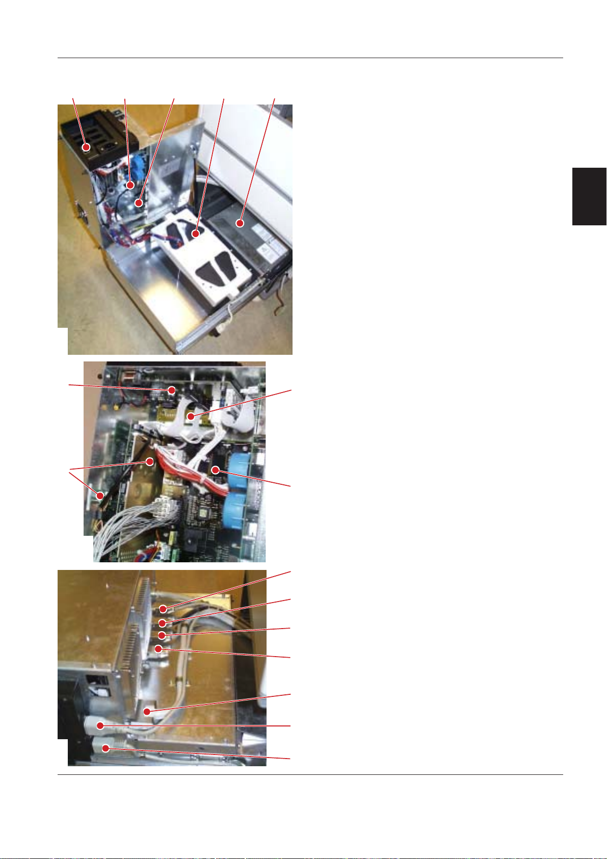
Battery drawer
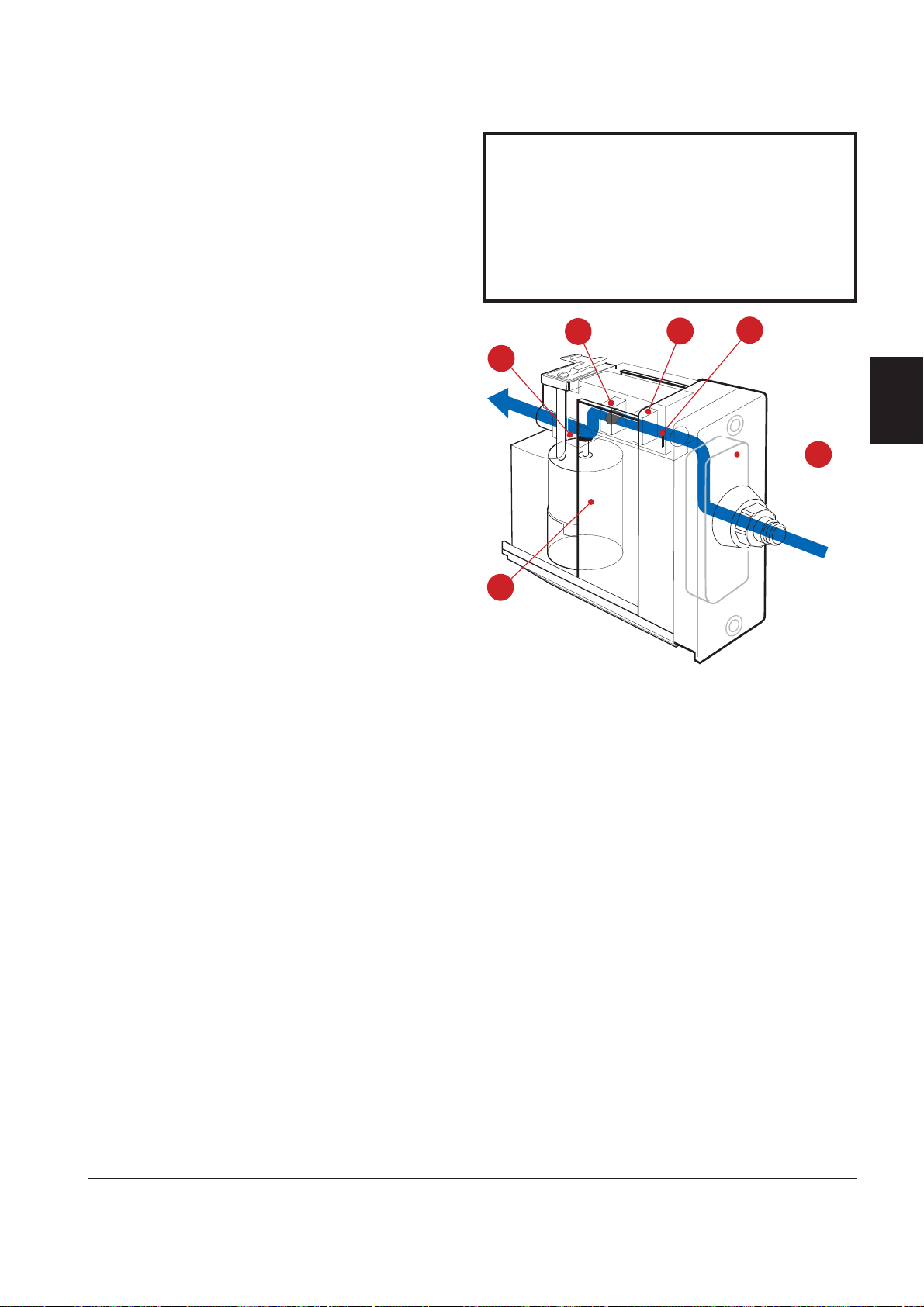
The battery drawer can be pulled out from the cart
for easy access. It contains functions for power
supply and communication:
1. AC/DC Converter
2. Internal battery. An optional Extra internal battery
can be installed to prolong the backup time.
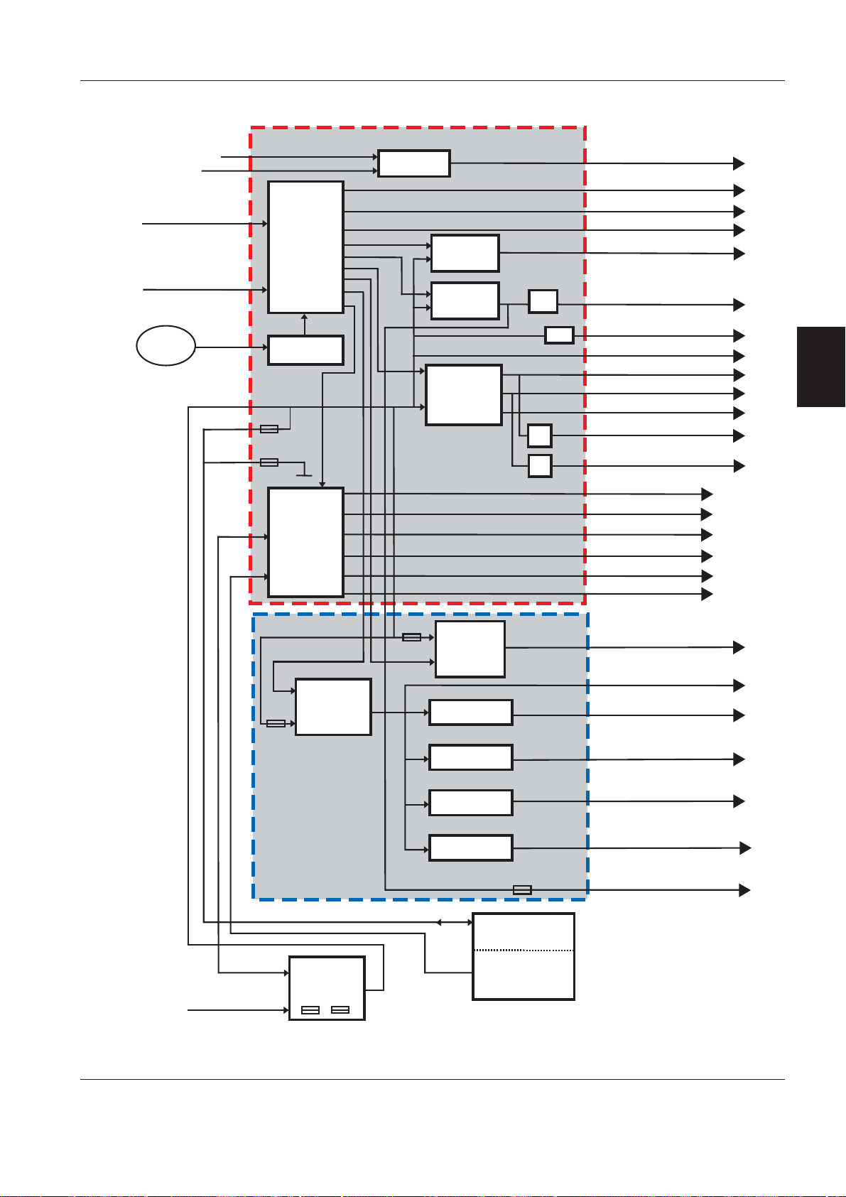
Included in the Battery drawer is also the Power &
2
Communication interface containing:
3. Communication ports
4. PC 1747 CAN/RS232 I
NTERFACE
5. PC 1753 DC/DC CONVERTER
6. PC 1675 POWER SUPPLY
7. MIB CONNECTOR (MIB = Medical Information Bus):
– PC 1761 for KION with S/N 03645 or lower.
– PC 1843 for KION / KION-i with S/N 03646 or
higher.
8. C
ONNECTOR board:
?
– PC 1754 for KION with S/N 03645 or lower.
– PC 1856 for KION / KION-i with S/N 03646 or
higher.
A
KN9002
OMMUNICATION INTERFACE board:
9. C
– PC A101 CPS N
PC A301 M
ETWORK PCB including the small
ONITOR OPTION AND SETUP MEMORY
BOARD for KION with S/N 03645 or lower.
=
– PC A110 IDS N
ETWORK PCB and PC A120 CAN/
MIB for KION / KION-i with S/N 03646 or higher
(not shown in illustration).
These PC boards are also included in the Siemens
patient monitor Communication/Power Supply
module alt. Infinity Docking Station module. For
further information regarding these modules,
refer e. g. to the SC 7000/9000XL or SC 9000
Service Manuals.
The following cables are connected to the Power &
Communication interface:
.
10. Multigas analyzer communication cable (RS232)
11. Multigas analyzer power cable (24 V DC)
12. DuoView cable (RS232 & supply voltage)
13. CAN loop-back
!
14. KION / KION-i Monitor communication cable
"
(TAXI and supply voltage)
15. Isolation transformer cable (optional)
16. AC/DC Converter cable.
KN9003
#
E382 E392E 061 01 02 02 Siemens-Elema AB
2 - 3
Introduction KION / KION-i
2
96=<;H
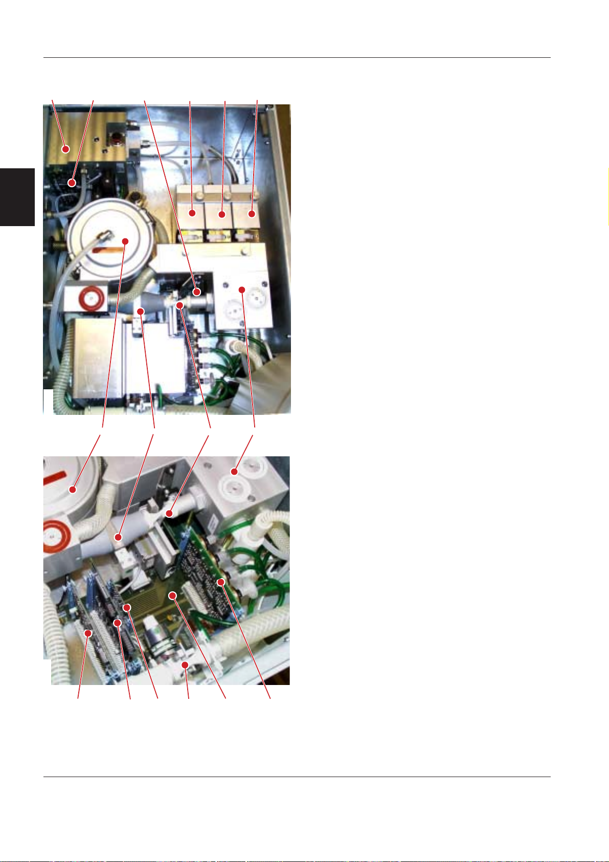
Pneumatic section
The pneumatic section, accessible when the top
cover and shield cover is removed, controls the
inspiratory fresh gas flow and the expiratory gas
flow.
The main parts inside the pneumatic section are:
1. Gas distribution block
2. PC 1720 W
ALL PRESSURE
3. PC 1765 VALVE INTERCONNECTION
4. Gas module AIR (N2O) – BP
5. Gas module O
6. Gas module Drive Gas AIR (O
– BP
2
)
2
7. Inspiratory gas block
8. Fresh gas pressure container
9. Inspiratory fresh gas flow transducer
10. Inspiratory fresh gas valve with PC 1751 S
TEP
MOTOR
11. PC 1737 MEASURING
KN9005 KN9004
@A ?
12. PC 1730 CONTROL
13. PC 1797 FRESH GAS FLOW (PC 1748 on units with
S/N 00125 – 01405)
14. PEEP valve
15. PC 1796 I
NTERCONNECTION (PC 1733 on units with
S/N 00125 – 01405)
16. PC 1750 T
RANSDUCER including four pressure
transducers:
– On PC 1750A/B, the four pressure transducers
are the integrated in PC 1750.
– As from PC 1750C or later, four separate
pressure transducers, PC 1781 P
RESSURE
TRANSDUCER board, are used (not shown in
illustration).
The PC board protective plate shown in the upper
illustration was introduced on KION workstations
delivered as from July 1998.
."
!
#
Siemens-Elema AB
E382 E392E 061 01 02 022 - 4
KION / KION-i Introduction
KN9006
69
H
;
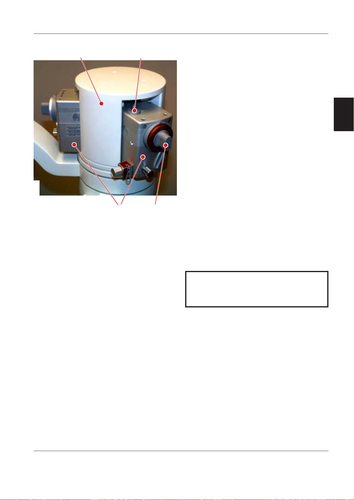
Vaporizer section
The vaporizers used in the KION / KION-i workstation
are the Precision Injection Vaporizers, PIVap.
The vaporizers are color-coded for the different
anesthetic liquids and the filling is key-indexed.
Three vaporizers can be mounted onto the vaporizer
magazine. The main functions are:
1. Vaporizer magazine. The magazine can be
2. PIVap vaporizers
3. Vaporizer locking lever
4. Vaporizer concentration knob. Only one vaporizer
Vaporizers for the following anesthetic agents are
available:
• Halothane
revolved to facilitate easy access to the active
2
vaporizer.
can be active at a time due to the interlocking
system. To activate the vaporizer; push-in and
turn the vaporizer concentration knob counterclockwise.
• Enflurane
• Isoflurane
• Sevoflurane
• Desflurane.
Handle the vaporizers with care when filled with
anesthetic liquids. Never turn them upside down
or lay them sideways.
E382 E392E 061 01 02 02 Siemens-Elema AB
2 - 5
Introduction KION / KION-i
2
9
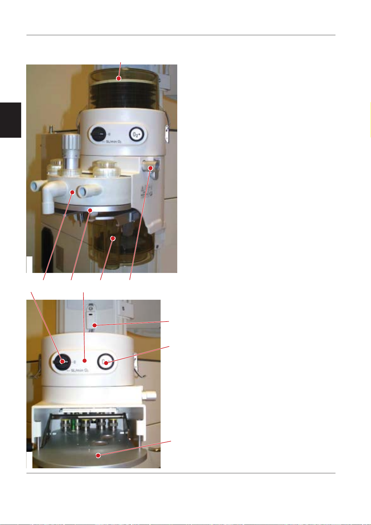
Patient unit
The patient unit controls the gas flow to and from the
patient. The main functions are:
1. Patient cassette. Removable unit containing
mushroom valves, expiratory flow transducer,
inspiratory and expiratory unidirectional valves
and the APL valve. The patient tubes and the
manual breathing bag are connected to the
patient cassette.
2. Support plate for patient cassette. There are five
solenoid valves and a mechanically controlled cutoff valve included in the support plate.
The solenoid valves are electrically connected to
PC 1755 P
parts are protected by a cover plate.
3. Bag-in bottle. The breathing bellows and the
bellows container are connected to the breathing
system when Circle System is selected.
A bellows position sensor (4) including PC 1766
BNB S
5. The CO
when Circle System is selected.
ATIENT CASSETTE VALVE CONTROL. All these
ENSOR is mounted on the cart.
Absorber purifies the rebreathing gas
2
KN9007
H
<6
=
@?
6. Auxiliary fresh gas outlet to be used in combination with external breathing systems.
7. The section Instant O
– Emergency O
2
supply contains the:
2
switch (8) marked 5 L/min O2.
When switched on, it secures a continuous gas
flow from the O
gas supply of approx. 5 l/min.
2
This function enables manual ventilation, e. g.
in case of ventilator malfunction.
–O
Flush push-button (9) marked O2+.
2
;
A gas flow of 35 – 75 l/min (depending on the
supply pressure) will be delivered to the
O
2
breathing system as long as this button is
A
pressed.
KN9008
H
Siemens-Elema AB
E382 E392E 061 01 02 022 - 6
KION / KION-i Introduction
KN9009
H6
User interface
Control panel
The control panel section consists of the:
1. Control panel housing.
2. Front panel mounted onto the Control panel
housing. The front panel is available in different
language versions.
3. PC 1672 CONTROL PANEL mounted inside the
control panel housing. The control panel selectors
and potentiometers are connected to PC 1672
CONTROL PANEL.
9
2
KN9010
6
KION Monitor
The KION Monitor (1) used on the KION workstation
is a Siemens Patient Monitor, SC 7000, SC 9000 or
SC 9000XL. The KION Monitor, that is mounted on
the D
an integrated part of the P
The KION Monitor is used not only for clinical
information but also for displaying technical
information during pre-use check, calibration and
troubleshooting of the KION workstation.
For information regarding the KION Monitor, refer to
the User's guides and the Service Manuals for the
Siemens Patient Monitors.
KN9011
E382 E392E 061 01 02 02 Siemens-Elema AB
OCKING STATION™, will make the KION workstation
ICK AND GO™ concept.
2 - 7
Introduction KION / KION-i
Electronic structure
General
The KION software can be divided into the following
functional electronic subsystems:
• Panel (PAN)
• Alarm (ALA)
2
• Measuring (MEA)
• Control (CON)
• Multigas analyzer interface (MGI)
• Monitor (MON)
• Power supply (PWR).
Panel
PAN
Alarm
ALA
KN9012
analyzer interface
Siemens-Elema AB
Measuring
MEA
Multigas
MGI
Power supply
PWR
Control
CON
Monitor
MON
E382 E392E 061 01 02 022 - 8
KION / KION-i Introduction
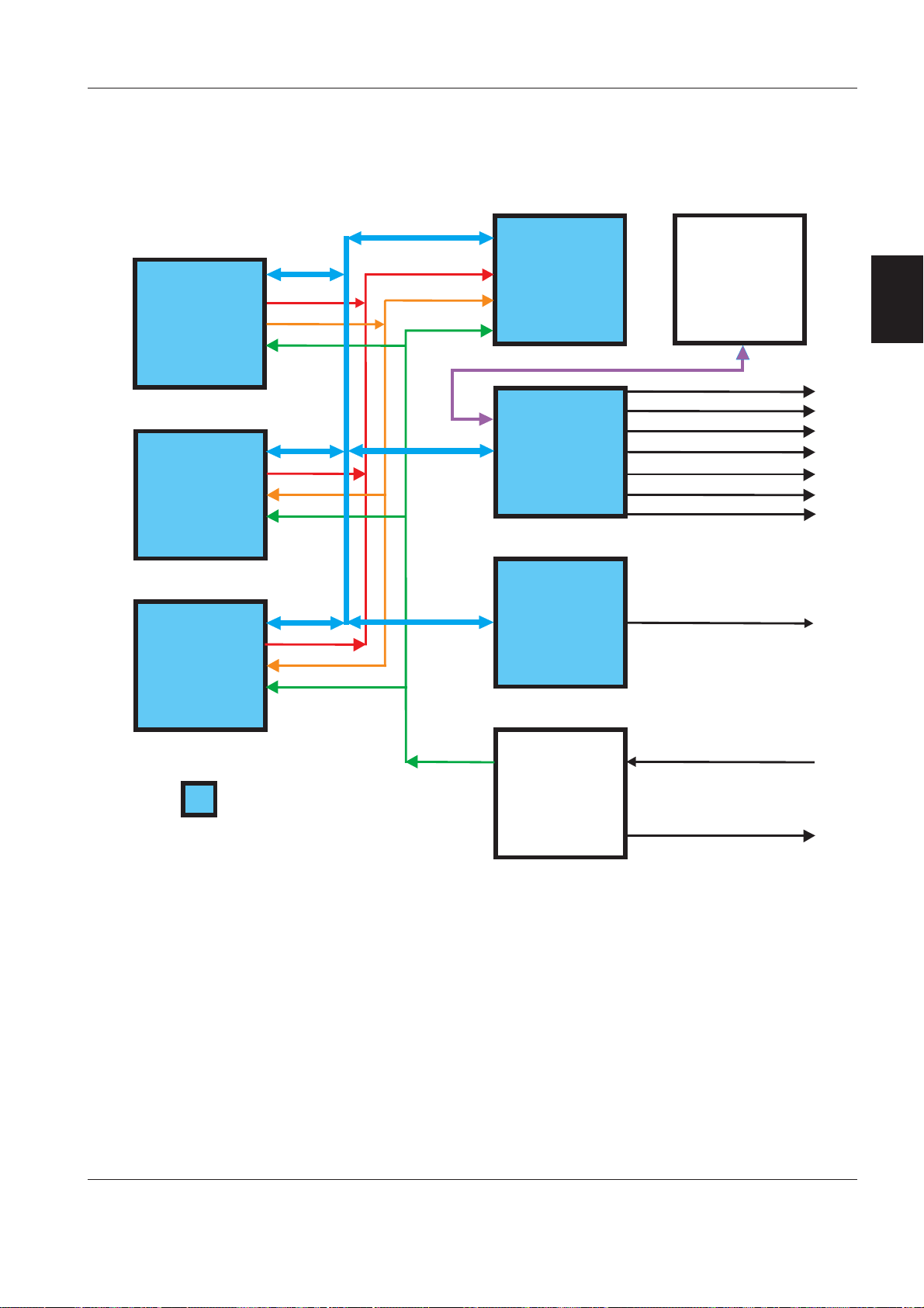
Internal communication
The diagram below shows the basic electrical signals
between the different electronic subsystems:
CAN bus
PAN
MEA
CON
Emergency line
Standby
Reset
ALA
TAXI bus
MON
MGI
KION
Monitor
CPS / IDS Diagnostic
SC 9000 Diagnostic
VGA output
CIS (RS232)
Recorder
Infinity Network
MIB 1 & 2
RS232 Interface
(multigas analyzer)
2
Reset
= CAN node
KN9013
CAN bus
Internal communication via CAN bus protocol (CAN =
Controller Area Network).
The CAN bus is a simple two-wire differential serial
bus system. The CAN bus operates in noisy electrical
environments with a high level of data integrity.
TAXI bus
Communication between the CPS/IDS and the KION
Monitor.
E382 E392E 061 01 02 02 Siemens-Elema AB
Emergency line
Digital signal in separate cabel for alarm distribution
in case of CAN bus malfunction.
Standby
Digital signal in separate cabel that activates standby
functions.
Reset
Digital signal in separate cabel that ensures a
controlled start of the microprocessors at a stable
voltage level.
PWR
Mains power
Power outputs (Optional
isolation transf ormer)
2 - 9

Introduction KION / KION-i
Panel (PAN)
The PAN-software is stored in an exchangable
program memory (PAN-PROM) mounted on
PC 1672 C
ONTROL PANEL.
The main functions of the PAN subsystem are:
• Forwarding panel settings to CON and MEA.
• Displaying set and measured parameters.
2
• Barometer calibration and forwarding of barometric
pressure.
• Adjusting display brightness.
• Supervision of ALA.
• Control panel check (displays and LEDs) at startup.
Alarm (ALA)
The ALA-software is stored in an exchangable
program memory (ALA-PROM) mounted on
PC 1672 C
ONTROL PANEL.
The main functions of the ALA subsystem are:
• Alarm gateway; transfers alarms from the different
subsystems to the MON subsystem for
presentation on the KION Monitor.
• Alarm backup in case of communication error with
the K
ION Monitor.
• System release at power-up.
• Supervision of power supply.
• Supervision and calculation of battery capacity.
• Supervision of system status (OFF/Standby/ON).
• Supervision of internal CAN-nodes.
Measuring (MEA)
The MEA-software is stored in an exchangable
program memory (MEA-PROM) mounted on
PC 1737 M
EASURING.
The main functions of the MEA subsystem are:
• Measuring, calculation and supervision of
expiratory flow (minute and tidal volume).
• Measuring and supervision of airway pressure
(software and hardware detection).
• Supervision of gas supply pressure.
• Heating, calibration and zeroing of the expiratory
flow transducer.
• Calibration of pressure transducers.
• Supervision of ”Disconnect”.
The measured values are distributed to the correct
subsystem via the CAN bus.
MEA handles alarm detection and forwards the
alarms to the ALA subsystem. Alarm limits are either
constant values or values set on the control panel.
Multigas analyzer interface (MGI)
The MGI-software is stored in an exchangable
program memory (MGI-PROM) mounted on
PC 1747 CAN/RS232 I
NTERFACE.
The main functions of the MGI subsystem are:
• Protocol converter between KION (CAN) and the
multigas analyzer (RS232).
• Startup of multigas analyzer.
• Handling E2PROM-data concerning system
configuration.
• Mains/battery indication on the control panel.
• Alarm silencing on the control panel.
Siemens-Elema AB
E382 E392E 061 01 02 022 - 10
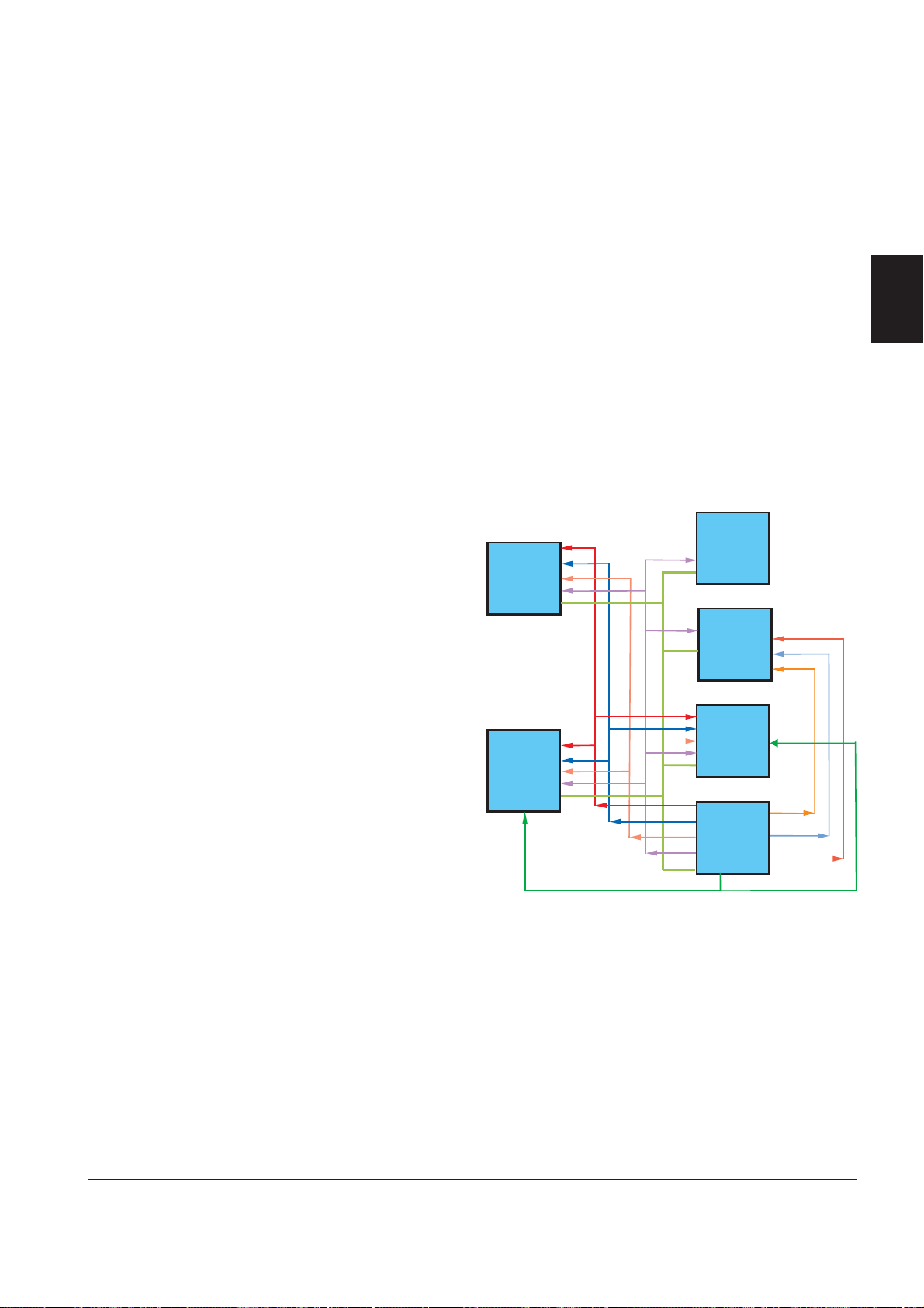
KION / KION-i Introduction
Panel
PAN
GND
+5 V
+15 V
+24 V
-15 V
+24 V_VALVE
+12 V
-12 V
+13 V
For supervision purposes
Multi gas
analyzer
interface
MGI
Monitor
MON
Alarm
ALA
Pneumatic
section
including
MEA
and
CON
Power supply
PWR
KN9014
Monitor (MON)
The Monitor (MON) subsystem includes the:
•C
OMMUNICATION INTERFACE, CPS alt. IDS Network PCB.
• PC 1754 C
• PC 1761 MIB C
C
ONNECTOR 2.
ONNECTOR alt. PC 1856 CONNECTOR.
ONNECTOR alt. PC 1843 MIB
• KION Monitor.
The C
OMMUNICATION INTERFACE is also included in the
Siemens Communication Power Supply (CPS) alt.
Infinity Docking Station (IDS) module.
The software in the C
OMMUNICATION INTERFACE , CPS-
SW alt. IDS-SW, and KION MONITOR-SW in the
KION Monitor is installed from a PC Card via the
KION Monitor.
The main functions of the MON subsystem are:
• Displaying patient parameters and wave forms.
• Displaying gas supply pressures.
• Displaying set and measured gas concentrations.
• Displaying alarms.
Power supply (PWR)
The Power supply (PWR) subsystem includes the:
• AC/DC Converter.
• Internal battery.
• PC 1753 DC/DC C
• PC 1675 P
OWER SUPPLY.
ONVERTER.
• Isolation transformer (if connected).
• Control of power-up and power-down sequences.
The Power supply subsystem is responsible for
converting mains power and battery power to the
voltage levels requested by the system. Power
supply will also supply these voltages to the electrical
parts within the system.
2
• Handling external communication.
Control (CON)
The CON-software (CON-SW) is stored in a FLASHPROM on PC 1730 C
ONTROL. New versions of the
CON-SW can be installed either by replacing PC 1730
or by using the Software download tool.
The main functions of the CON subsystem are:
• Control of breathing systems.
• Control of ventilation modes.
• Control and measuring of fresh gas flow including
gas mixture selection (O
/AIR, O2/N2O).
2
• Calculation of inspiratory flow.
• Calculation of spontaneous breathing frequency.
• Conversion of panel settings and feedback to
panel.
• Controlling the ”Pre-use check” and the
”Calibration” sequences.
• Control of all electromagnetic valves.
E382 E392E 061 01 02 02 Siemens-Elema AB
2 - 11

Introduction KION / KION-i
Notes
2
Siemens-Elema AB
E382 E392E 061 01 02 022 - 12

KION / KION-i Description of functions
Only personnel trained and authorized
by Siemens shall be permitted to
perform installation, service or
maintenance of the KION / KION-i
workstation.
Make sure to prepare the KION / KION-i
workstation properly before disassembling and
assembling. Refer to section ”Hazard notices” in
chapter ”Important”.
Any service or maintenance must be noted in a
log book.
Discard disposable, replaced and left-over parts in
accordance with appropriate industrial and
environmental standards.
After any installation, maintenance or service
intervention in the KION / KION-i, perform a
”Calibration” and a ”Function check”.
Refer to the ”KION / KION-i anesthesia
workstation – Operating Manual” for details.
3. Description of functions
Battery drawer................................................... 3 - 2
1. AC/DC Converter...................................... 3 - 2
2. Internal battery ......................................... 3 - 2
3. Extra internal battery (optional)................ 3 - 3
4. Power & Communication interface .......... 3 - 3
Pneumatic section ............................................. 3 - 6
5. Gas distribution block ............................... 3 - 6
6. Inspiratory control .................................... 3 - 7
7. PEEP valve................................................ 3 - 10
8. PC 1733 / PC 1796 Interconnection......... 3 - 11
9. PC 1730 Control ....................................... 3 - 11
10. PC 1737 Measuring.................................. 3 - 16
11. PC 1750 Transducer................................. 3 - 18
Vaporizer section ............................................... 3 - 18
12. Vaporizer magazine .................................. 3 - 18
13. PIVap vaporizers ....................................... 3 - 19
Patient unit ......................................................... 3 - 20
14. Patient cassette ........................................ 3 - 20
15. Support plate for patient cassette ........... 3 - 22
16. Bag-in-bottle ............................................. 3 - 22
17. CO
18. Instant O
19. Auxiliary fresh gas outlet.......................... 3 - 23
User interface .................................................... 3 - 24
20. Control panel ............................................ 3 - 24
21. KION Monitor ........................................... 3 - 24
Optional equipment ........................................... 3 - 25
22. DuoView ................................................... 3 - 25
23. Multigas analyzer ..................................... 3 - 25
24. Isolation transformer ................................ 3 - 25
25. Backup gas supply ................................... 3 - 26
26. Suction equipment ................................... 3 - 26
27. Auxiliary O
28. Gas evacuation ......................................... 3 - 26
29. MiniOX 3000 Oxygen Monitor ................. 3 - 27
30. Accessory and Monitor shelf ................... 3 - 27
31. Medside Data Station for KION ............... 3 - 27
Absorber ........................................... 3 - 23
2
supply...................................... 3 - 23
2
supply ................................... 3 - 26
2
3
E382 E392E 061 01 02 02
Siemens-Elema AB
3 - 1

Description of functions KION / KION-i
About this chapter
The Description of functions is divided in two levels:
Basic principles
•
– Basic principles containing a
survey of the function. This text is written with an
italic typeface. The text refers to the diagram
”Basic principles” in chapter ”Diagrams”.
• Enhanced information – Enhanced information
about the function. Normal typeface is used in this
text. This text refers to the following diagrams in
chapter ”Diagrams”:
– Pneumatic block diagram
– Electronic interconnection.
Text written in S
3
the diagrams mentioned above.
MALL CAPS refers to block names in
Battery drawer
The battery drawer contains functions for power
supply and communication.
1. AC/DC Converter
The AC/DC CONVERTER, containing the mains power
rectifier and the transformer, is a complete unit that
is mounted on the Power & Communication interface
casing. The AC/DC C
to PC 1675 POWER SUPPLY.
There are two mains power inlet fuses in the AC/DC
C
ONVERTER. The fuses and the AC/DC CONVERTER FAN
are the only spare parts available for the AC/DC
C
ONVERTER.
The AC/DC C
ONVERTER FAN pulls cooling air into the
converter compartment. If the fan fails, the signal
FAN_FAIL generates a diagnostic log message.
If the AC/DC C
194°F), e. g. due to fan failure, the AC/DC CONVERTER
will be disabled. The KION / KION-i workstation will
then be power supplied by the I
When the AC/DC C
automatically be enabled.
Technical data for the AC/DC C
• AC/DC C
• AC/DC C
ONVERTER input: 100 – 240 V AC, 50 – 60 Hz.
ONVERTER output: Max. 400 W, output
voltage level 21–30 V DC controlled by an analog
signal from the Charging/Discharging control block
on PC 1675 P
• Fuses: T 6.3 AL / 250 V AC (2 pcs).
ONVERTER is electrically connected
ONVERTER is overheated (above +90°C /
NTERNAL BATTERY.
ONVERTER cools down, it will
ONVERTER:
OWER SUPPLY.
2. Internal battery
The INTERNAL BATTERY (two serial connected 12 V
sealed lead acid batteries) supplies the KION / KION-i
workstation with backup power for min. 30 minutes
with full charged battery.
NTERNAL BATTERY is used as an internal 24 V
The I
backup. The batteries are rated 12 V, approx. 24 Ah.
NTERNAL BATTERY is continously charged when the
The I
KION / KION-i workstation is connected to mains
power. Charging time for empty batteries is approx.
6 hours.
The actual I
displayed on the KION Monitor. The battery capacity
indication, bargraph with %, is related to actual
battery voltage. ”100%” is indicated when trickle
charge level is reached (fully charged).
The following applies concerning battery voltage
supply:
• Battery voltage supply is used as soon as the
AC/DC C
voltage (e.g. if the power consumption is too high).
• If the AC/DC C
19 V (e.g. at loss of mains power), a ”Switching to
battery” alarm indicates that battery voltage supply
is in use.
• First battery alarm ”Limited battery capacity” is
activated when battery voltage reaches below 23 V
(22 V if an E
These voltage levels correspond to ”20%”
indicated.
• Second battery alarm ”No battery capacity” is
activated 10 minutes after first battery alarm or
when battery voltage is below 22 V (21.5 V if an
XTRA INTERNAL BATTERY is connected). These voltage
E
levels correspond to ”0 %” indicated.
• All functions will be cut off when battery voltage
reaches below 21 V.
Battery capacity indication and alarms are generated
via the ALA power supervision function.
Service interval for the I
• The I
”Twelve months maintenance”.
• The I
years. After replacement, allow the batteries to
recharge before clinical use of the KION / KION-i
workstation.
The lifetime of the I
used frequently to supply the KION / KION-i
workstation with operating power or if the battery
temperature is above +50°C (122°F) e. g. due to
ATTERY DRAWER FAN failure. In such case, it is
B
recommended to check the I
shorter intervals than 12 months.
NTERNAL BATTERY capacity is continously
ONVERTER voltage is less than the battery
ONVERTER output voltage is below
XTRA INTERNAL BATTERY is connected).
NTERNAL BATTERY:
NTERNAL BATTERY must be checked during the
NTERNAL BATTERY must be replaced every three
NTERNAL BATTERY is reduced if it is
NTERNAL BATTERY with
3 - 2
Siemens-Elema AB
E382 E392E 061 01 02 02

KION / KION-i Description of functions
Batteries (spare parts) are not supplied by Siemens.
They must be purchased locally. Tested batteries for
use in the KION / KION-i workstation are listed below.
No other batteries must be used.
• CSB EVX-12260
http://www.csb-battery.com)
(
• Newmax FNC 12240
http://www.newmaxbattery.co.kr)
(
• Power-Sonic PS-12260 NB
(
http://www.power-sonic.com)
• Hitachi HP24-12
For further information regarding the batteries and
battery suppliers, refer to the Internet address stated
at each battery type above or to the Siemens Medical
Solutions, Customer Service Intranet-Portal at
http://cs.med.siemens.de.
3. Extra internal battery (optional)
EXTRA INTERNAL BATTERY (two serial connected 12 V
sealed lead acid batteries) for extended backup time.
Gives, together with the I
NTERNAL BATTERY, a total
backup time of approx. 120 minutes with full charged
battery.
For information regarding battery type, function and
service interval, see section 2. ”Internal battery”
above.
There are two versions of the battery cable; one
version to be used if a standard I
connected and one version to be used if an E
NTERNAL BATTERY is
XTRA
INTERNAL BATTERY is connected. Thus, if an extra EXTRA
INTERNAL BATTERY is installed, the battery cable must
be replaced.
4. Power & Communication Interface
The following functions are included in the POWER &
C
OMMUNICATION INTERFACE:
• Communication ports – PC 1754 C
PC 1856 C
• PC 1761 MIB C
C
ONNECTOR 2.
•C
OMMUNICATION INTERFACE, CPS network PCB alt.
ONNECTOR.
ONNECTOR alt. PC 1843 MIB
IDS network PCB.
• PC 1747 CAN/RS232 I
• PC 1753 DC/DC C
NTERFACE.
ONVERTER. Generates +12 V, +13
V and a fused +24 V for power supply of the
multigas analyzer.
• PC 1675 POWER SUPPLY. Voltage supply and battery
charge/capacity check. Generates +15 V, - 15 V,
+5 V and 24 V for the KION system.
•B
ATTERY DRAWER FAN.
ONNECTOR alt.
PC 1754 Connector / PC 1856 Connector
Communication ports for connecting the KION /
KION-i workstation to network, service options, etc.
The communication ports are integrated parts of the
PC board.
There are two versions of the PC board:
• PC 1754 C
• PC 1856 C
ONNECTOR for KION with CPS.
ONNECTOR for KION / KION-i with IDS.
Pin configuration and signal names can be found in
chapter ”Diagrams”.
PC 1761 MIB Connector / PC 1843 MIB Connector 2
Converts monitoring parameters to MIB protocol.
MIB = Medical Information Bus.
There are two versions of the PC board:
• PC 1761 MIB C
• PC 1843 MIB C
ONNECTOR for KION with CPS.
ONNECTOR 2 for KION / KION-i with
IDS.
Pin configuration and signal names can be found in
chapter ”Diagrams”.
Communication interface
There are two versions of the C
OMMUNICATION INTERFACE
board:
• For KION with S/N 03645 or lower: PC A101CPS
N
ETWORK PCB including the small PC A301 MONITOR
OPTION AND SETUP MEMORY BOARD. These PC boards
are also included in the Siemens patient monitor
Communication/Power Supply module.
• For KION / KION-i with S/N 03646 or higher:
PC A110 IDS NETWORK PCB and PC A120 CAN/MIB.
This PC board is also included in the Siemens
Infinity Docking Station module.
The CPS/IDS software (CPS-SW alt. IDS-SW) is
installed from a PC Card via the KION Monitor.
For further information regarding the Communication/
Power Supply module or Infinity Docking Station
module, refer to e. g. SC 7000/9000XL or SC 9000
Service Manuals.
PC 1747 CAN/RS232 Interface
Protocol converter between KION (CAN) and the
multigas analyzer (RS232).
The MGI-software is stored in an exchangable
program memory (MGI-PROM) mounted on PC 1747
CAN/RS232 I
NTERFACE.
3
E382 E392E 061 01 02 02
Siemens-Elema AB
3 - 3

Description of functions KION / KION-i
PC 1753 DC/DC Converter
This description also refers to the block diagram
”Power supply – Main functions”.
PC 1753 DC/DC C
from PC 1675 P
ONVERTER is supplied with +24 V
OWER SUPPLY and generates:
• +12 V to connected equipment (lamp, recorder,
MIB, CPS/IDS Diagnostic and DuoView).
• +13 V to the KION Monitor.
• A fused +24 V to the multigas analyzer.
There are three fuses on PC 1753:
• F1/PC 1753 = 15 A / 32 V. Cuts the +24 V power
3
supply to the DC/DC C
disables the +12 V power supply to connected
equipment. No alarm is activated.
ONVERTER 24/12 V which
• F2/PC 1753 = 15 A / 32 V. Cuts the +24 V power
supply to the DC/DC C
ONVERTER 24/13 V which
disables the +13 V power supply to the KION
Monitor. The KION Monitor will run on its internal
battery and alarm is activated.
• F3/PC 1753 = 7.5 A / 32 V. Cuts +24 V power
supply to the multi gasanalyzer. Alarm is activated.
• Battery status and measure signals from the block
Charging/Discharging control is supplied to ALA.
• Power supply of the system will be cut at Low
battery voltage or at System Off.
There are two fuses on PC 1675:
• F1/PC 1675 = 30 A / 32 V. Battery short-circuit
protection. The internal battery is disconnected and
alarm is activated.
• F2/PC 1675 = 20 A / 32 V. Protects the internal
battery from failures on PC 1675. The internal
battery is disconnected and alarm is activated.
Battery Drawer Fan
The B
ATTERY DRAWER FAN pulls air out of the battery
drawer compartments. If the fan fails, the signal
FAN_FAIL generates a diagnostic log message.
If the temperature in the battery drawer
compartment is above 45 – 50°C (113 – 122°F), e. g.
due to B
multigas analyzer and the lifetime of the I
ATTERY DRAWER FAN failure, the function of the
NTERNAL
BATTERY may be affected.
PC 1675 Power Supply
This description also refers to the block diagram
”Power supply – Main functions”.
The main functions are:
• Generates and distributes +15 V, - 15 V and +5 V to
the different KION subsystems. Also generates
+12 V and -12 V for the CPS/IDS via linear
regulators.
• The Logic & Timing block handles different time
delays for voltages at Power On:
– The input signal MEAS_INHIBIT comes from ALA
in order to stop the battery capacity check.
– The input signal DISABLE_VALVES comes from
ALA, CON or MEA in order to disable
+24 V_VALVE (stop power supply to gas
modules) e.g. at upper pressure alarm.
• Power supply to gas modules, +24V_VALVE, will
also be cut at Low battery voltage or at System
Off.
ATTERY DRAWER FAN is power supplied by +24V_FAN.
•B
As from KION S/N 01501, this voltage is temperature controlled by an NTC resistor at connector
P123. Reduced fan speed up to 25°C (77)°F. Linear
increased up to max. speed at 45°C (113°F).
• Power supervision function in the ALA subsystem
ATIENT CASSETTE VALVE CONTROL is power
and P
supplied by +24V_PTC.
3 - 4
Siemens-Elema AB
E382 E392E 061 01 02 02
KION / KION-i Description of functions
PC 1675
FAN_FAIL_AC_DC
FAN_SENSE.
Battery measuring control
MEAS_INHIBIT.H
Control of valve voltage
DISABLE_VALVES.L
Operator
ON/OFF
PSU_ON.H24
On/Off switch
F2 / 20 A
F1 / 30 A
Charging/
Discharging
Logic
&
Timing
control
Fan logic
Time delay
switch
Time delay
switch
DC/DC-
converter
+15/-15/+5 V
Power Supply
Reg
PTC
Reg
Reg
FAN_FAIL.H (ALA)
POWER_DOWN.L
MAINS.H H (ALA)
POWER_ON_RESET.L
+24V_VALVE
+24V_FAN
+24V_PTC
+24V_PSU_SWITCH
+15 V
-15 V
+5 V
+12 V CPS/IDS
-12 V CPS/IDS
BATT_LARGE.L
DISCHARGE.H
BATT_CYCLE.H
DISCHARGE_CURRENT
CHARGE_CURRENT
BATT_VOLTAGE
Status
and
measure
signals
to ALA
3
KN9015
Mains power
DC/DC-
converter
24/12 V
F1 / 15 A
PC 1753
DC/DC Converter
AC/DC
converter
6.3 A
F2 / 15 A
DC/DC-
converter
24/13 V
Current limiter
Current limiter
Current limiter
Current limiter
Battery selector
F3 / 7.5 A
Battery
Temp. sensor
+13 V (KION Monitor)
+12 V (Lamp)
+12 V @ 1.8 A (2 pcs) (Recorder)
+12 V @ 0.32 A (2 pcs) (MIB)
+12 V @ 0.42 A
+12 V @ 1.3 A (DuoView)
+24 V (Multigas analyzer)
(CPS/IDS
Diagnostic)
Block diagram: Power supply – Main functions
E382 E392E 061 01 02 02
Siemens-Elema AB
3 - 5

Description of functions KION / KION-i
Pneumatic section
5. Gas distribution block
Gas supply from hospital central gas supply and/or
from gas cylinders are connected to this block.
The main functions are:
• Three gas inlets to connect gas from the hospital
central gas supply.
• PC 1720 W
measures the hospital central gas supply
pressures.
• The breathing gas and drive gas delivered to the
KION workstation sub-units are electronically and
pneumatically controlled by the G
VALVES.
3
• The two preset pressure regulators mounted on
the G
the gases delivered to the patient cassettes
mushroom valves and to the block I
SUPPLY.
• A number of gas inlets and outlets for connection
of the optional B
UXILIARY O
A
KION Workstation.
Gas inlets and outlet
The gas inlets are three couplings used to connect
gas from the hospital central gas supply.
The design of the gas inlet nipples and the color
marking varies according to different national
standards.
The gas inlet channels (inside the gas distribution
block) are equipped with gas inlet filters and spring
loaded one-way valves, OV1 – OV3. The gas inlet
filters and the one-way valves must be replaced
during the ”Twelve months maintenance”.
The O
2
optional equipment that requires O
The design of the gas outlet nipple and the color
marking varies according to different national
standards.
ALL PRESSURE mounted on the block
AS SELECTION
AS DISTRIBUTION BLOCK regulates the pressure in
NSTANT O
ACKUP GAS SUPPLY MANIFOLD,
SUPPLY and SUCTION EQUIPMENT to the
2
outlet is one coupling used to connect
supply.
2
Gas selection valves
The different gases delivered to the G
controlled as follows in the G
• Gas going to G
AS MODULE AIR (N
AS DISTRIBUTION BLOCK:
Controlled by the solenoid valve EMV6. AIR or N
AS MODULES are
O) – BP:
2
O
2
breathing gas depending on settings on the control
panel. Cuts automatically the N
O supply if O
2
2
supply pressure drops below 220 kPa (2.2 bar).
Opens automatically the N
O supply at O2 supply
2
pressure above 240 kPa (2.4 bar).
• Gas going to G
The O
G
breathing gas is delivered directly to the
2
AS MODULE O
AS MODULE O
– BP and is not controlled by any
2
– BP: Only O2.
2
solenoid valve on the GAS DISTRIBUTION BLOCK.
• Gas going to G
AS MODULE DRIVE GAS AIR (O
):
2
Controlled by the solenoid valve EMV7. Supplies
normally AIR but changes automatically to O
2
AIR supply pressure drops below 200 kPa (2.0 bar)
or if the solenoid valve drive voltage fails.
if the
2
Pressure regulators
There are two preset pressure regulators mounted
on the G
AS DISTRIBUTION BLOCK:
• REG1 regulates the pressure in the mushroom
valve control gas supply (AIR or O
depending on
2
EMV7 mode) used by EMV1 – 5. The preset
pressure is 20 kPa ( 0.2 bar). For adjustment of
REG1, refer to the tool ”Pressure Tester 0.2 bar
Regulator.
• REG2 regulates the pressure of the breathing gas
) to the block INSTANT O2 SUPPLY. The preset
(O
2
pressure is 320 kPa ( 3.2 bar).
Backup gas inlets
AS DISTRIBUTION BLOCK is equipped with three
The G
backup gas inlets used when gases from the optional
ACKUP GAS SUPPLY MANIFOLD are connected. These
B
inlets are plugged if not used.
PC 1720 Wall Pressure
There are two main functions on PC 1720 W
ALL
PRESSURE:
• Three pressure transducers including amplifiers.
Measures the pressure in the gases connected to
the gas inlets (from the hospital central gas supply).
There are no tube connections to the transducers,
the PC board is mounted firmly onto gas outlets in
AS DISTRIBUTION BLOCK. The gas outlets are
the G
equipped with seals to prevent leakage between
AS DISTRIBUTION BLOCK and the PC board.
the G
• Valve driver. A drive stage for the gas selection
valves EMV6 and EMV7.
3 - 6
Siemens-Elema AB
Gas outlets for auxiliary equipment
There are two extra gas outlets on the G
AS
DISTRIBUTION BLOCK, one for O2 and one for AIR. These
outlets can be used to supply optional equipment,
such as A
UXILIARY O
SUPPLY and SUCTION EQUIPMENT,
2
with O2 and AIR.
E382 E392E 061 01 02 02
KION / KION-i Description of functions
4
3
5
6
2
1
KN9016
6. Inspiratory control
Controls the gas delivered to the breathing system.
The main functions are:
• The three GAS M
ODULES
. They are basically of the
same design and function as the gas modules
(inspiratory valves) in the Servo Ventilator 300.
• Five safety valves, SV1 – 4 and SV8.
•F
RESH GAS PRESSURE CONTAINER
to create the working
pressure for the fresh gas supply.
• Inspiratory fresh gas channel that measures and
regulates the fresh gas to the breathing system.
The GAS MODULES are factory calibrated.
The adjustment potentiometer located at the top
of each G
AS MODULE (Type I) must not be
adjusted.
Each G
AS MODULE must not be disassembled
further than described in chapter ”Maintenance”.
Gas modules
3
There are two different versions of the gas module:
• Type I recognized by the metal nozzle unit.
• Type II recognized by the plastic nozzle unit.
As from S/N 01501, Type I was replaced by Type II in
the production of KION workstation. For information
regarding compatibility between Type I and Type II,
refer to SpeedInfo 008/02 EM LSS.
If not stated otherwise, this functional description is
valid for both versions.
The three G
•G
AS MODULE AIR (N
the V
AS MODULE O
•G
MAGAZINE.
•G
AS MODULE DRIVE GAS AIR (O
AS MODULES are:
O) – BP supplies AIR or N2O to
APORIZER MAGAZINE.
2
– BP supplies O2 to the VAPORIZER
2
) supplies AIR or O
2
1.Filter
2. Inspiratory valve temperature sensor
3. Supply pressure transducer
4. Flow transducer (Delta pressure transducer and net)
5. Nozzle unit with valve diaphragm
6. Inspiratory solenoid
2
as drive gas to the REBREATHING SECTION.
The G
AS MODULES marked BP are modified to handle
the backpressure created when supplying fresh gas
to vaporizers. Max. flow from the gas modules
modified for backpressure is reduced to 2 l/s.
The modification concerns PC boards inside the gas
module and the nozzle unit. Without these modifications, the backpressure would disable the
diaphragms closing function.
AS MODULES are pneumatically connected to the
The G
I
NSPIRATORY GAS BLOCK and electrically connected to
PC 1765 V
ALVE INTERCONNECTION.
Air inlet:
Gases from the G
to the inlet tube connectors on the G
AS DISTRIBUTION BLOCK are connected
AS MODULES. The
tube connectors and the corresponding tubes have
different diametres to prevent faulty gas
connections.
The filter housing and the filter cover is provided with
matching guide pins. These guide pins prevents
mounting the filter cover (with inlet tube connectors)
on wrong G
AS MODULE.
A non-return valve for the gas inlet is located in the
inlet filter cover. This valve will suppress short
pressure drops in the gas supply. The non-return
valve is also designed to slowly evacuate
compressed gas from the G
supply to the G
AS MODULE is disconnected.
AS MODULE if the gas
E382 E392E 061 01 02 02
Siemens-Elema AB
3 - 7

Description of functions KION / KION-i
Filter:
The filter protects the system from particles in the
gas delivered to the air inlet. The filter must be
replaced during the ”Twelve months maintenance”.
Inspiratory valve temperature sensor:
The temperature of the supplied gas is measured by
the inspiratory valve temperature sensor. This sensor
is situated in the gas flow.
The output signal from this sensor is used to
compensate for the gas density variations due to
temperature.
Supply pressure transducer:
3
The pressure of the supplied gas is measured by the
supply pressure transducer.
The output signal from this transducer is amplified. It
is then used to calculate the absolute pressure of the
gas to compensate for gas density variations due to
pressure.
Delta pressure transducer and net:
The gas flows through a net (resistance) which
causes a pressure drop. The pressure is measured
on both sides of this net and the differential pressure
value is then amplified.
Nozzle unit:
The nozzle unit contains a valve diaphragm. The valve
diaphragm, controlled by the inspiratory solenoid,
regulates the gas flow through the G
AS MODULE.
Metal nozzle units (Type I) modified for backpressure
must be used together with a small washer that is
placed on top of the inspiratory solenoid. This washer
will support the diaphragm and distributes the
backpressure over a larger area on the diaphragm.
This function is integrated in the plastic nozzle units
(Type II) and the small washer is not used in these
AS MODULES.
G
The nozzle units are provided with a mechanical key
to prevent that the nozzle unit is mounted into wrong
AS MODULE.
G
An O-ring and the valve diaphragm (Type I) or the
complete plastic nozzle unit (Type II) must be
replaced during the ”Twelve months maintenance”.
After replacement, allow the diaphragm to settle
during approx. 10 minutes before gas pressure is
connected to the G
AS MODULE.
Inspiratory solenoid:
The gas flow through the G
AS MODULE is regulated by
the inspiratory solenoid via the nozzle unit.
The current supplied to the solenoid is regulated so
that the gas module will deliver a gas flow according
to the front panel settings.
Gas module key:
AS MODULES are provided with a mechanical key
The G
to prevent that the GAS MODULE is mounted in the
wrong slot.
The key consists of a plastic guide mounted underneath the G
AS MODULE and a corresponding guide
mounted on the pneumatic section base.
Safety valves
NSPIRATORY CONTROL block contains four safety
The I
valves:
• SV1 is a spring-loaded valve preset to open at 600
kPa (6 bar). Protects the vaporizers in case of
failure in GAS MODULES AIR (N2O) – BP or O2 – BP.
• SV2 is a magnetic valve preset to open at 14 kPa
(140 mbar). Will release overpressures created in
AG-IN-BOTTLE, e. g. if the patient is coughing.
the B
Will also protect the BAG-IN-BOTTLE in case of failure
in the G
AS MODULE DRIVE GAS AIR (O
).
2
• SV3 is a magnetic valve preset to open at 18 kPa
(180 mbar). Protects the F
RESH GAS PRESSURE
CONTAINER and the INSPIRATORY FRESH GAS VALVE.
• SV4 is a magnetic valve preset to open at 14 kPa
(140 mbar). Protects the patient from high pressure
in the fresh gas.
• SV8 is a magnetic valve preset to open at -3.5 kPa
(-35 mbar). Protects the pressure transducers from
negative pressures created during use of closed
suction catheter systems.
The magnetic valves (SV2 – SV4 and SV 8) contain a
permanent magnet that affects the metal valve cone.
The distance between the magnet and the valve cone
is preset to open the valve when the pressure limit is
reached.
Do not cover the visable hole in the center of valves
SV2 – SV4. If this hole is covered, the valve will not
open.
3 - 8
Siemens-Elema AB
E382 E392E 061 01 02 02

KION / KION-i Description of functions
Fresh gas pressure container
The fresh gas from the V
RESH GAS PRESSURE CONTAINER above the big rubber
F
APORIZER MAGAZINE enters the
diaphragm mounted inside the container. A piston,
that is pushed up by the constant gas pressure
regulated by REG3, affects the diaphragm and the
fresh gas is pushed out from the F
RESH GAS PRESSURE
CONTAINER. The preset pressure 100 kPa (1.0 bar) on
REG3 creates a working pressure of 8–15 kPa (80–
150 mbar) inside the F
PC 1752 D
IAPHRAGM POSITION SENSOR inside the
RESH GAS PRESSURE CONTAINER.
container, in combination with one magnetic washer
inside the piston, indicates the position of the piston,
i. e. if the container is almost empty. This level signal
is used to enable the G
AS MODULES for a flow of fresh
gas to the vaporizers. Disabling of the gas modules,
when the container is full, is calculated by CON.
The piston and PC 1752 are matched and delivered
as a spare part kit. They must be replaced at the
same time.
The diaphragm and the piston seal must be replaced
during the ”Twelve months maintenance”.
Inspiratory fresh gas channel
The fresh gas passes:
• The inspiratory fresh gas flow transducer with its
amplifier PC 1797 F
RESH GAS FLOW (PC1748 on
units with S/N 00125– 01405).
• The I
NSPIRATORY FRESH GAS VALVE with PC 1751 STEP
MOTOR (control function).
• The one-way valve OV4. This valve has a built-in
leakage at low pressures and is not appropriate to
use during leakage check.
from the block INSTANT O2 SUPPLY is connected to
O
2
the fresh gas channel in the I
NSPIRATORY GAS BLOCK.
Inspiratory fresh gas flow transducer:
The gas flows through the flow transducer in two
parallel channels, one large main channel and one
small measuring channel. The main channel is fitted
with a wire mesh net, the resistance of which causes
a certain proportion of the gas to flow through the
measuring channel. The flow through and the
differential pressure across the measuring channel
acts on a small metal disc (”flag”) which, via a metal
pin, presses on a small semiconductor strain gauge.
This strain gauge consists of diffused resistors on
both sides of an elastic silicone rod. The resistors are
connected as a part of a Wheatstone bridge, the
other part of which is situated on PC 1797/PC 1748
RESH GAS FLOW. The more flow in the channel, the
F
higher the pressure on the strain gauge. The change
in resistance in the Wheatstone bridge is converted
to a corresponding signal voltage.
Cleaning of the flow transducer is described in
chapter ”Routine cleaning” in the Operating Manual.
3
E382 E392E 061 01 02 02
Siemens-Elema AB
3 - 9

Description of functions KION / KION-i
Inspiratory Fresh Gas Valve with PC 1751 Step Motor:
NSPIRATORY FRESH GAS VALVE is operated by a step
The I
motor with a special shape slotted cam mounted on
the motor shaft.
The gas flows through the fresh gas valve tube
(silicone rubber) that is a part of the inspiratory fresh
gas channel. The gas flow through the valve tube is
then regulated by a movable lever arm that squeezes
the valve tube against a fixed arm. This movable arm
is attached to the cam and transfers the step motors
rotation to a controlled opening position of the valve
tube.
The change in flow through the valve tube is microstep controlled by the step motor. The step motor is
controlled by PC 1751 that is a part of the step motor
3
assembly.
PC 175 1 S
two photo detectors. When the step motor reaches
either end position of the cam slot, the light beam
between the LED and the corresponding photo
detector is interrupted by a cam screen. The cam
screen is a part of the slotted cam mounted on the
motor shaft. This will generate an end position signal
from PC 1751.
The position of the LEDs / detectors in relation to the
cam screen is very important. If a LED / detector gets
out of position, or if they fail, this will cause the step
motor to ”rattle” because end positions are not
properly indicated.
When power supply to the I
VALVE is switched off (or if the power supply fails),
the step motor will always end up with the
inspiratory valve in fully opened position.
The fresh gas valve tube must be replaced during the
”Six months maintenance” and the ”Twelve months
maintenance”.
TEP MOTOR is equipped with two LEDs and
NSPIRATORY FRESH GAS
7. PEEP valve
The expiratory gas flow is regulated by the PEEP
VALVE. This valve also regulates PEEP pressure if set
on the C
The PEEP V
magnet acting on a lever arm which squeezes the
expiratory valve tube (silicone rubber) against a fixed
arm. The more the magnet is activated, the more the
valve will move towards the closing position.
When power supply to the magnet is switched off,
the valve will be fully opened because of the spring.
This ensures that the patient always can exhale
through the ventilator at a power failure.
The PEEP valve is controlled by CON. At a PEEP
setting, information from the PEEP pressure transducer is used to regulate the valve position during
expiration.
The PEEP valve tube must be replaced during the
”Six months maintenance” and the ”Twelve months
maintenance”.
ONTROL PANEL.
ALVE comprises a spring loaded pull
3 - 10
Siemens-Elema AB
E382 E392E 061 01 02 02

KION / KION-i Description of functions
8. PC 1733 / PC 1796 Interconnection
The PC 1733 / PC 1796 INTERCONNECTION electrically
connects a number of units in the KION workstation.
The only electronic functions on this PC board are
output filters and PTC resistors.
There are two versions of this PC board:
• PC 1733 on units with S/N 00125–01405.
• PC 1796 on units with S/N 01501 and higher.
Four PC boards are mounted in PC board connectors
on the upper side of the PC 1796:
• PC 1730 C
• PC 1737 MEASURING
• PC 1750 TRANSDUCER
• PC 1797 FRESH GAS FLOW.
With PC 1733 I
Instead, PC 1748 F
connected to PC 1733 via a cable.
The under side of PC 1733/PC 1796, accessible
behind a trolley cover, contains cable connectors for:
• Patient unit cable.
• Pneumatic section cable.
• Control panel cable.
• Pressure transducers on the optional B
SUPPLY MANIFOLD.
The PC board inputs/outputs are described in chapter
”Diagrams”.
ONTROL
NTERCONNECTION, PC 1797 is not used.
RESH GAS FLOW is used and
ACKUP GAS
9. PC 1730 Control
Controls flow, pressure, composition and concentration in the gas delivered to the patient. All ventilation
mode functionality is controlled by this unit.
PC 1730 C
executes the CON-software (CON-SW) that is stored
in a FLASH-PROM. New versions of the CON-SW
can be installed either by replacing PC 1730 or by
using the Software download tool.
The main functions of PC 1730 C
• General parameters (used or created by CON).
• Fresh gas production (excluding control of
anesthetic agent type and concentration).
• Inspiratory fresh gas control.
• Drive gas for rebreathing.
• Regulation of expiration.
General parameters
Some of the general parameters used or created by
CON are:
• Pressure: Input pressure signals from the four
pressure transducers on PC 1750 are supplied via
the A/D C
expiration.
• Timing: Output Insp. time and Exp. time signals
are generated. These are used by MEA to control
zeroing of the flow transducers.
• Fresh gas outlet: Input signal from the Hall sensor
in the A
valve is opened. This signal is used to light up a
LED on the C
• Pressure alarm: Input signal from MEA indicating
that upper pressure limit is reached. Used to stop
inspiration time and immediately start expiration
time. This will open the PEEP V
other valves in safe positions.
ONTROL contains a microprocessor that
ONTROL are:
ONVERTER for regulation of inspiration and
UXILIARY FRESH GAS OUTLET indicates when the
ONTROL PANEL.
ALVE and to set the
3
E382 E392E 061 01 02 02
Siemens-Elema AB
3 - 11
Description of functions KION / KION-i
AIR
N2OO
2
Fresh gas from vaporizer
GAS MODULE AIR (N2O) - BP
FRESH GAS
PRESSURE CONTAINER
8 - 15 kPa (80 - 150 mbar)
PC 1752
Position
sensor
OFF
GAS MODULE O2 - BP
EMV 6
O
2
Level
PIVap
3
Parallell
I/O
D/A
converter
Gas
flow
KN9017
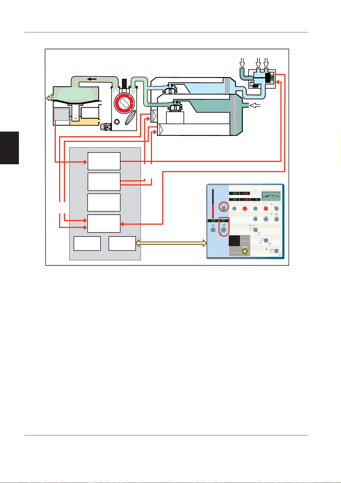
PC 1730 – Fresh gas production
Fresh gas production depends on the following
settings:
• Selection of gas mixture – O
• Preset O
concentration.
2
• Anesthetic agent – type and concentration.
Air/N2O selection:
Information about gas combination selected on the
ONTROL PANEL, O
C
/Air or O2/N2O, is distributed via the
2
CAN bus to PC 1730 CONTROL.
The electrically and pneumatically operated EMV 6
activates the selection. The switching of EMV 6 is
monitored.
N
O supply is automatically cut if the O2 supply
2
pressure drops.
Pulse width
modulator
converter
Processor
CON-SW
PC 1730 Control
A/D
CAN
interface
/Air or O2/N2O.
2
Flow ref.
Bar. ref.
Zeroing
Gas selection
Valve position
18
CAN bus
Fresh Gas Flow l/min
16
14
12
10
8
6
4
3
O2/Air
2
1,5
1,0
0,5
0,3
0,1
Preset O2 Conc.%
28
21
!
Exp.Tidal Volume ml
Tidal Volume ml
Minute Volume l/min Exp. Minute Vol. l/min
O2/N2O
LowerVol. Alarm Limit CMV b/min Upper Press. Limit Press. Level above PEEP
Volume
6
4
2
1
Hand Ventilation
Volume Control
Pressure Support
Mains/Batt. Charg.
Battery On
No Screen
Alarm
Pressure Control
Alarm Silence
100
8
50 60
40
10
70
30
20
80
20
30
90
90
40
10
50
I:E Ratio PEEP Trigger Sensitivity
1:1
2:1
1:2
4:1
1:3
Circle System
Non-Rebreathing
Auxiliary
Fresh Gas Outlet
Airway Pressure
40
6
0
0
2
8
0
0
100
0
2
-
cmH2O
mbar
50
30
60
40
20
40
30
70
50
10
80
80
20
90
90
10
60
Press. Flow
10
5
15
0
20
Off
On
!
Standby
Off
Gas Modules:
Two of the G
AS MODULES deliver fresh gas to
vaporizers according to the O2 concentration set on
ONTROL PANEL.
the C
The control signals, delivered from the D/A converter
on PC 1730 C
ONTROL to the GAS MODULES, are:
• Flow reference (desired value – ATP).
• Barometric pressure signal.
• Zeroing of flow transducer.
Each G
sent back to PC 1730 C
AS MODULE creates its gas flow signal which is
ONTROL.
Fresh Gas Pressure Container:
The level signal from the D
IAPHRAGM POSITION SENSOR
indicates if the FRESH GAS PRESSURE CONTAINER is empty.
These indications are used to enable the G
AS MODULES
for a flow of fresh gas to vaporizers.
3 - 12
Siemens-Elema AB
E382 E392E 061 01 02 02
 Loading...