

Page 1
7
987
Operating Instructions
KF8806
Test unit KF8806 for use with burner controls LAL... and LFL...
Persons using the KF8806 test unit must be familiar with the control sequence and the different control functions of
burner controls LAL... and LFL...
For detailed information on the burner controls, refer to the relevant Data Sheets (7153 for LAL... and 7451 for LFL...).
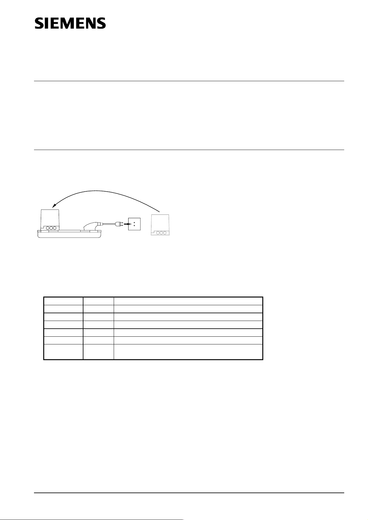
These types of burner controls can be tested independent of the burner with which they are used (see diagram A).
The control and checking signals can be picked up at jacks 1...24 to be fed to the KF8888 signal recorder, for
instance.
Diagram A
Testing the burner control independent of the burner
·
Plug burner control into the KF8806 test unit
· Select QRA..., QRB... FE or RAR...with the detector selector, depending on the type of burner control to be tested
· Toggle switch positions:
«H» «O»
«bv» «I» With LAL2... and LFL1...
«LP» «PA» Automatic air pressure signal when power is fed to terminal 6
«R» «O»
«LR» «30 %» Low-fire
«SA» «Z» Air damper fully closed
Detector
simulation
·
Connect test unit to the mains supply (AC 220...240 V / 50...60 Hz)
· Set switches «H» and «R» to «I» (ON).
Provided the burner control is in proper working order and has not gone to lockout, the startup sequence will now
commence
· Turn rotary knob of air damper actuator «SA» to «A» as soon as the signal lamp of actuator «SA» starts flashing at
the beginning of the prepurge time.
This simulates the actuator’s FULLY OPEN position and – at the same time – feeds power to terminal 8 so that lamp
«SM» (= synchronous motor of the programming mechanism) lights up
· Turn rotary knob of air damper actuator «SA» to «M» as soon as signal lamp «SA» starts flashing again on
completion of the prepurge time (simulation of low-fire position «MIN»)
· On completion of the startup sequence, output control can be simulated with switch «LR». The auxiliary changeover
switch of the actuator feeds power to «BV2».
The signal lamp of the actuator continues to flash until the actuator’s switch changes to position «A» (analogously)
· Postpurging is triggered by opening the start control loop: Switch «R» set to «O»
Turn rotary knob to «Z» as soon as the signal lamp of actuator «SA» starts flashing, to simulate the air damper’s
FULLY CLOSED position
«AUT» Automatic flame signal on completion of the 1st safety time
7987z02/0999
HVAC Products CC1B7987en 31.10.2002 1/3
Page 2
· Simulation of faults
To check the burner control’s supervisory functions, switch «LP», the rotary knob for simulating the actuator’s
position and the flame signal switch can be used to simulate faults:
PO N.C. contact of air pressure switch «LP» constantly closed, «no air pressure»
PI N.O. contact of air pressure switch «LP» constantly open
Example: Contact welded
Z, A, M If, during the period of time from the start command to the completion of the prepurge time, the rotary knob for simulating the
actuator position is not in the required position (signal lamp flashes), the startup sequence will be discontinued (no power present at
terminal 8)
No flame signal
Example: No flame on completion of the safety time or loss of flame during operation
Flame signal always available
Example: Simulation of extraneous light, self-igniting UV tube or similar defects
·
Check measurements with the LAL1... and LAL2... (series 02)
Measurement of pull-in and drop-out values of flame relay with flame supervision using the QRB... photoresistive
detector:
–
If available, connect a potentiometer 0...1 MW (with scale) to jacks 22 and 23
– Set the potentiometer to 1 MW
– Let burner control run to its start position
– In the start position, the flame relay must safely pull in at about 470 kW, thus triggering lockout.
This resistance value applies at AC 100...110 V / AC 220...240 V
– Initiate startup with switch «R»
– Set the potentiometer to 180 kW as soon as signal lamp «BV1» lights up.
At this resistance value during operation, the flame relay must safely pull in
– Set the potentiometer to 390 kW.
At this resistance value, the flame relay must safely drop out when the burner control is in its operating position
·
Check measurements with the LFL1... (series 01)
Measurement of operating voltage with QRA... and ionization probe during the detector test:
– Let burner control run to its start position
– Use a voltmeter (for AC) with an internal resistance of 10 MW
– Measure the mains voltage since the measured values also depend on the available voltage
Test voltage Voltmeter connected to
jacks
For UV detector
QRA...
For ionization probe
FE
22 and 23 AC 110 V
22 and 24 AC 110 V
Umains Measured value
Approx. AC 330V ±10 %
AC 220 V
Approx. AC 315 V ±10 %
AC 220 V
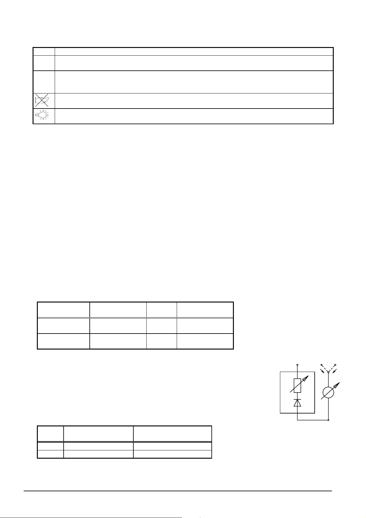
Measurement of the flame relay’s response threshold in the case of flame supervision
22 23
with the UV detector QRA... or the ionization probe
Let burner control run to its start position
–
– Use a DC microammeter with an internal resistance of max. 5 kW
R
FL
– Set detector selector to «O»
I
QRA
24
I
Ion
+
-
7987a01/0999
Type of
detector
FE 24 Approx. 5 µA
QRA... 23 Approx. 70 µA
Measuring instrument
connected to jack
Response threshold at
AC 220...240 V
Flame Measuring
simulation instrument
2/3 CC1B7987en 31.10.2002 HVAC Products
Page 3

Automatic test (endurance test)
For the endurance test, the following settings are required:
· Set switch «R-W» in the current path to terminal 5 to «Aut.»
· Set the interval (in minutes) at which the tests shall be made, using switch «S» on the timer.
The interval between 2 tests must exceed the length of the burners control´s startup sequence, including the idle
steps (time «t20»)
· Intermediate interval times can be set with potentiometer «P»
R-W-Aut.
4
2
1
8
0,5
16
SP
TIMER ON MINUTE
7987z03/0800
Ó 2002 Siemens Building Technologies
Subject to change!
HVAC Products CC1B7987en 31.10.2002 3/3
 Loading...