

Siemens ISI EN 50295,50295 Brochure
AS-Interface
according to EN 50295
Siemens IK PI
.
2004
6/2 Introduction
6/2 Transmission technology
6/3 Configuration example
6/4 System components
6/5 Technical specifications
6/6 A/B technique
6/8 AS-Interface Safety at work
6/8 Introduction
6/9 AS-Interface safety monitors
6/11 AS-Interface safe compact modules
6/15 AS-Interface position switches
6/18 AS-Interface cable-operated switches
6/19 AS-Interface light curtains and
light arrays for Category 4
6/24 AS-Interface laser scanner LS4
6/30 AS-Interface EMERGENCY STOP
pushbuttons
6/30 Accessories
AS-Interface Master
6/31 Masters for SIMATIC S5
6/31 CP 2430
6/33 Masters for SIMATIC S7
6/33 CP 142-2
6/35 CP 243-2
6/37 CP 343-2
6/39 CP 343-2 P
ST 70
1
)
Masters for SIMATIC C7
Sec. 8
2
)
AS-Interface network transitions
DP/AS Interface Link 20E
DP/AS Interface Link 65
AS-Interface Slaves
6/41 I/O modules for operation in the field
6/41 Introduction
6/43 Digital I/O modules IP67 – K60
6/51 Digital I/O modules IP68 / IP69K – K60R
6/56 Digital I/O modules IP67 – K45
6/64 Digital I/O modules IP67 –
application modules
6/71 Analog I/O modules IP67 – K60
6/74 Pneumatic I/O modules
6/75 I/O modules for operation
in IP20 control cabinet
6/75 Introduction
6/77 SlimLine
6/88 F90 module
6/93 Flat module
6/94 Special integrated solutions
6/94 AS-Interface Communication modules
AS-Interface Slaves (continued)
6/98 Modules with special functions
6/98 Counter modules
6/100 Earth fault detection modules
6/103 Overvoltage protection module
6/105 AS-Interface motor starters and
IP65/67 load feeders
6/105 AS-Interface compact starters IP65
(400 V AC)
6/113 AS-Interface motor starters IP67 (24 V DC)
6/116 ECOFAST motor and soft starter
6/117 AS-Interface motor starters and
IP20 load feeders
6/117 Load feeder modules IP20
LV 10
3
)
AS-Interface Direct/Reverse Starter
6/121 SIRIUS soft starters
LV 10
3
)
Communications capable contactors
55 to 250 kW
LV 10
3
)
Double relays and transformers
6/122 SIGNUM pushbuttons and
indicator lights
6/122 AS-Interface F-Adapter for
EMERGENCY STOP command devices
6/123 AS-Interface enclosure
6/124 AS-Interface customized enclosures
and front panel modules
6/133 AS-Interface LED displays
6/134 AS-Interface for LOGO!
LV 10
3
)
AS-Interface signal columns
6/135 AS-Interface power supply units
6/135 Introduction
6/136 Power supply units IP20
6/141 Power supply units IP65
6/143 Transmission media
6/143 AS-Interface shaped cable
6/145 System components and accessories
6/145 Repeater/Extender
6/147 Addressing units
6/149 Diagnostic units
6/151 Miscellaneous accessories
6/152 Documentation
1
)
see Catalog ST 70
”Products for Totally Integrated
Automation and Micro Automation“
2
)
see Section 8
3
)
see Catalog LV 10
”Controlgear for Industry“
Siemens IK PI · 2004
6/2
AS-Interface
Transmission technology
Introduction
6
■
Overview
Transmission method
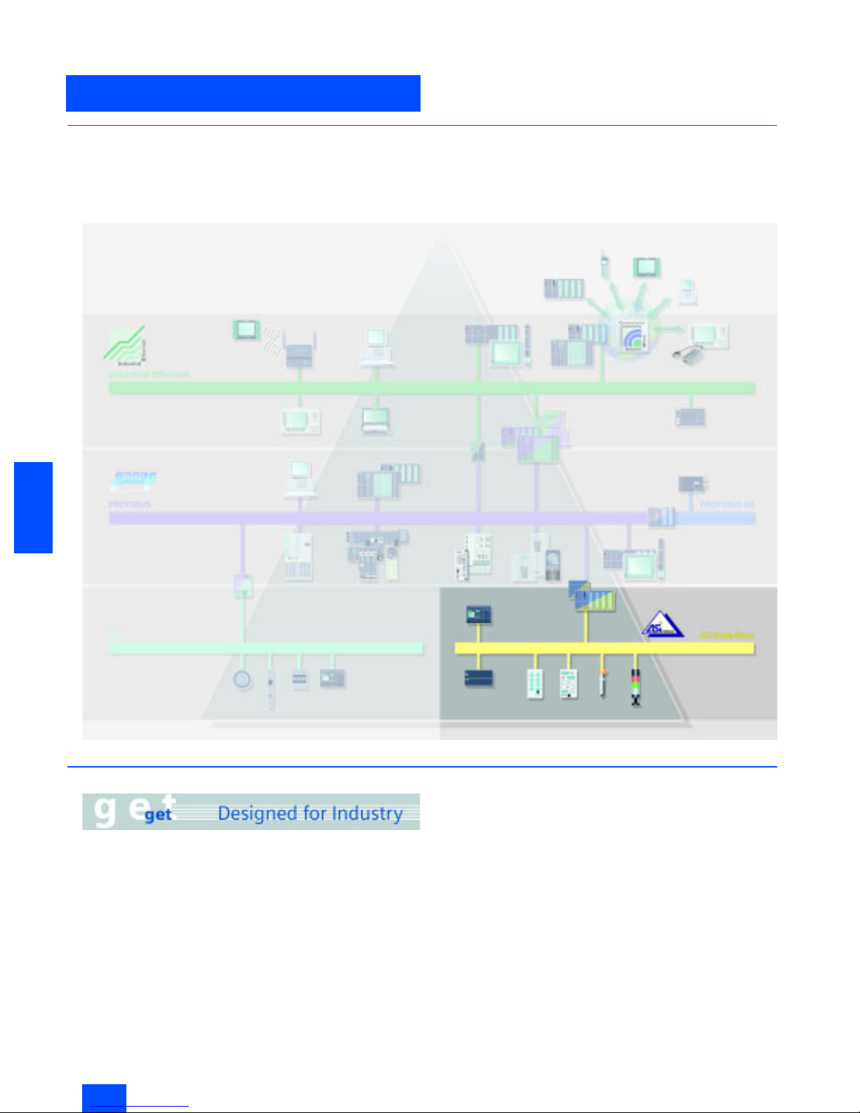
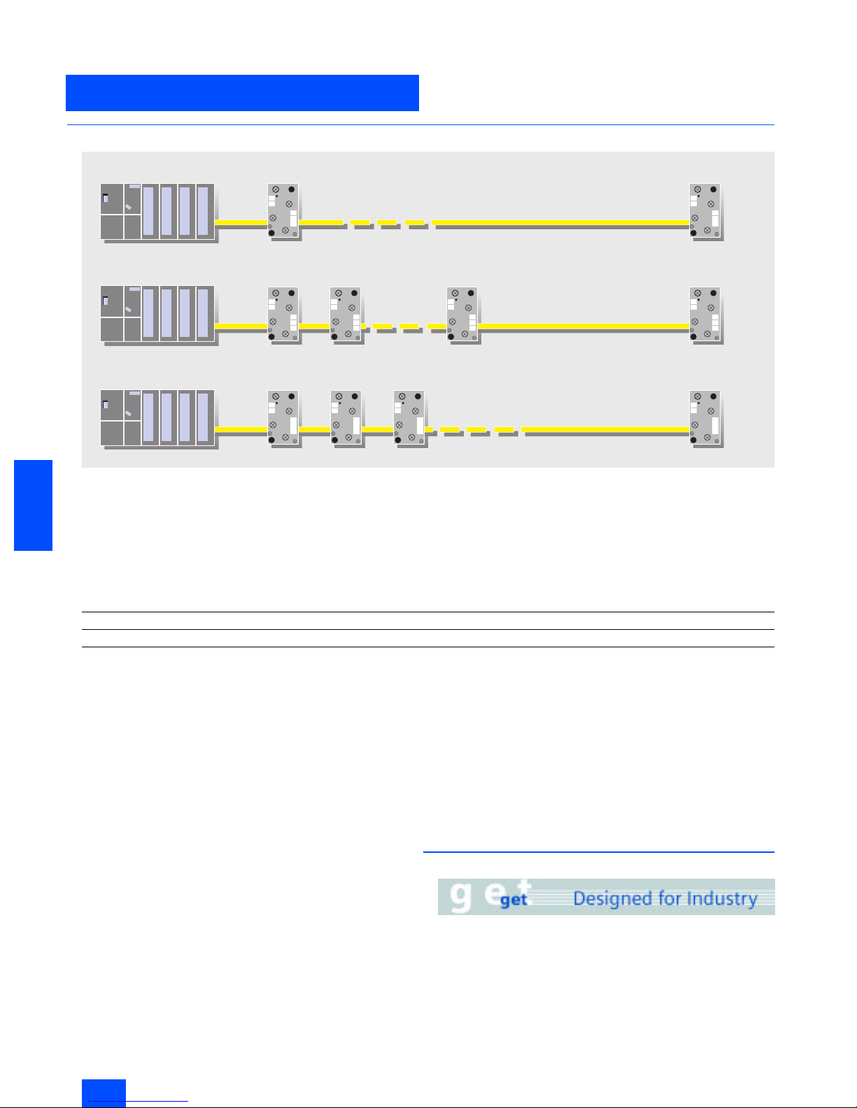
A significant feature of the AS-Interface technology is the use of
a common, two-wire cable for data transmission and distribution
of auxiliary power to sensors/actuators.
An AS-Interface power supply unit, which meets the requirements of the AS-Interface transmission technology, is used for
this system. The AS-Interface shaped cable provides mechanical coding and thus prevents polarity reversal; penetration
terminals are used for simple contacting.
■
Benefits
Cabinets that were previously overflowing with complicated control line wiring and marshalling distributors can now be replaced
by AS-Interface.
The AS-Interface cable can be connected at any point, thanks to
specially developed wiring and connection using the insulation
displacement method.
This concept gives you tremendous flexibility and considerably
cuts costs.
The AS-Interface is a single master system. Communications
processors (CPs) are available for SIMATIC
®
systems which
control process or field communication as masters.
The system expansion now allows double the quantity of slaves
(max. 62) to be operated on AS-Interface. The analog values are
now also preprocessed in the master. For direct connection of
AS-Interface to PROFIBUS DP, DP/AS-Interface Link 20E is
available. Using this DP/AS-Interface link, the AS-Interface can
be used as a subnet for PROFIBUS DP.
The AS-Interface is an open standard. Leading manufacturers
of actuators and sensors support AS-Interface worldwide.
Interested companies can obtain the electrical and mechanical
specifications from the AS-Interface Association on request.
$6,QWHUIDFH
Siemens IK PI · 2004
6/3
AS-Interface
Introduction
Configuration examples
6
■
Function
Operating modes
In general, the master interfaces distinguish between the following operating modes:
I/O data transfer
The inputs and outputs of the binary AS-Interface slaves are
read and written in this operating mode.
Analog value transmission
The AS-Interface masters according to the Complete
AS-Interface Specification V2.1 support integrated analog value
processing. This means that data exchange with analog
AS-Interface slaves (according to analog profile 7.3 or 7.4) is just
as easy as with digital slaves.
Command interface
In addition to the I/O data exchange with binary and analog ASInterface slaves, the AS-Interface masters offer a range of additional functions through the command interface.
This means that, from user programs, slave addresses can be
assigned, parameter values can be transferred and diagnostic
information can be read out.
■
Design
Process or field communication
AS-Interface is used wherever individual actuators and sensors
are physically distributed throughout the machine (e.g. in a bottling plant or on a production line).
AS-Interface replaces complicated wiring harnesses and connects binary and analog actuators and sensors, such as proximity switches, valves or indicator lights, to a controller (e.g. SIMATIC) or PC.
In practice this means: The installation runs without problems
because data and power are transported through a single common cable. No specialist know-how is required for installation
and startup. In addition, the simple installation and clear structuring of the wiring and special cable design not only considerably reduce the risk of faults but also reduce service and maintenance costs.
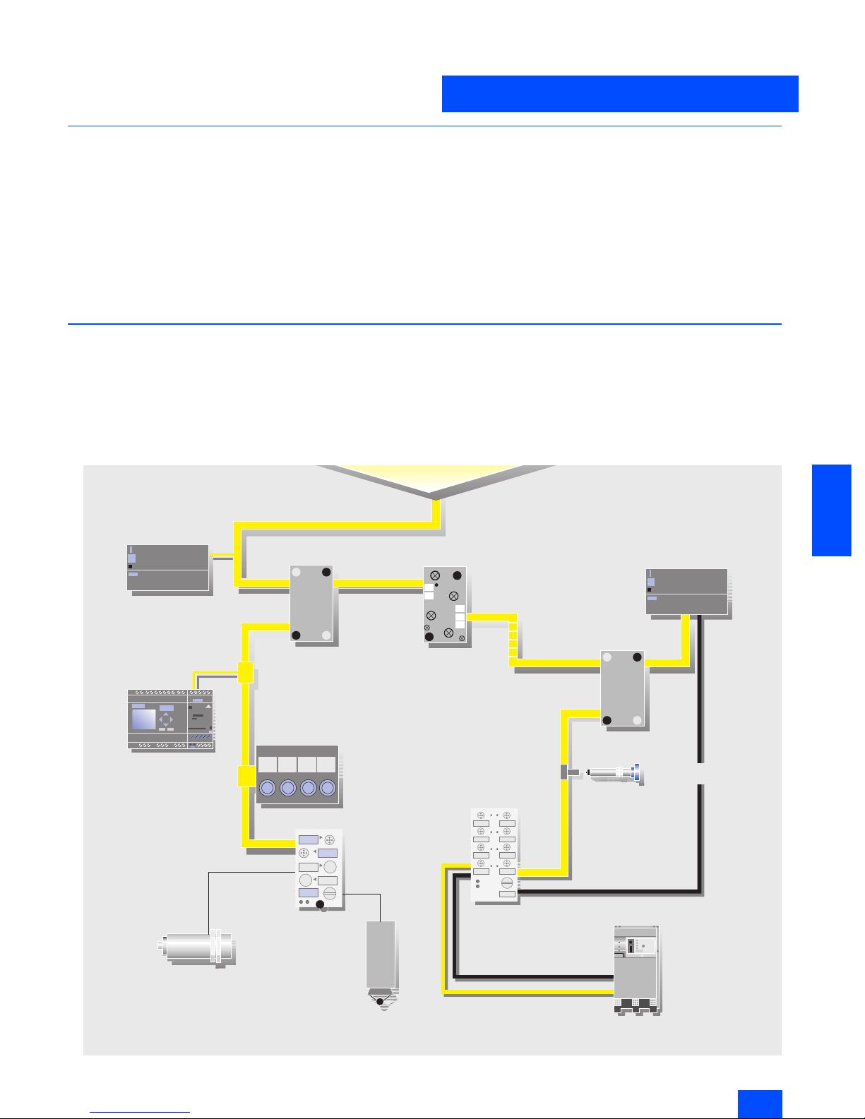
Example of a system configuration
G_IK10_XX_20027
Connection via AS-Interface cable
AS-Interface distributor
(without AS-Interface chip)
AS-Interface cable
AS-Interface
power section
Branch M12
K60
AS-Interface distributor
(without AS-Interface chip)
Repeater
LOGO!
Operator panel
K45
(with AS-Interface chip)
for connection of
standard sensors
Standard encoders
e.g. position switches
Standard sensor
e.g. inductive BERO
Compact starter IP 65
max 100 m
SONAR BERO
with int. AS-Interface
AS-Interface
power section
Siemens IK PI · 2004
6/4
AS-Interface
System components
Introduction
6
■
Overview
System components
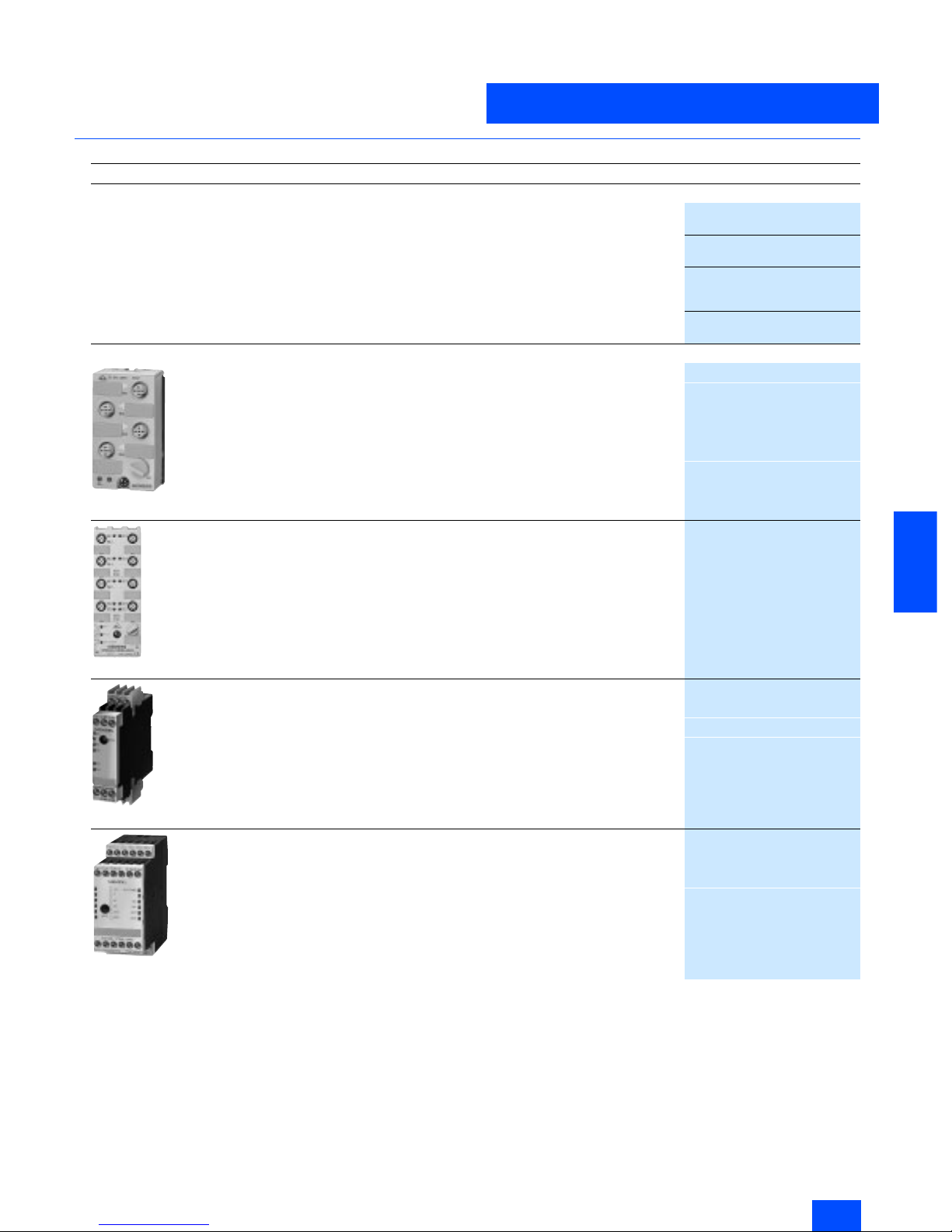
Many system components are available to implement communications. The basic components of a system installation are:
• Master interfaces for central control units such as SIMATIC S5
and SIMATIC S7, distributed I/Os ET 200
®
M/X,
• AS-Interface shaped cables
• Network components such as repeaters/extenders
• The power supply unit for supplying power to the slaves,
modules for connecting standard sensors/actuators
• Actuators and sensors with integrated ASIC slave
• Fail-safe modules for transmission of secure data through
AS-Interface,
• Address programming device for setting the slave address.
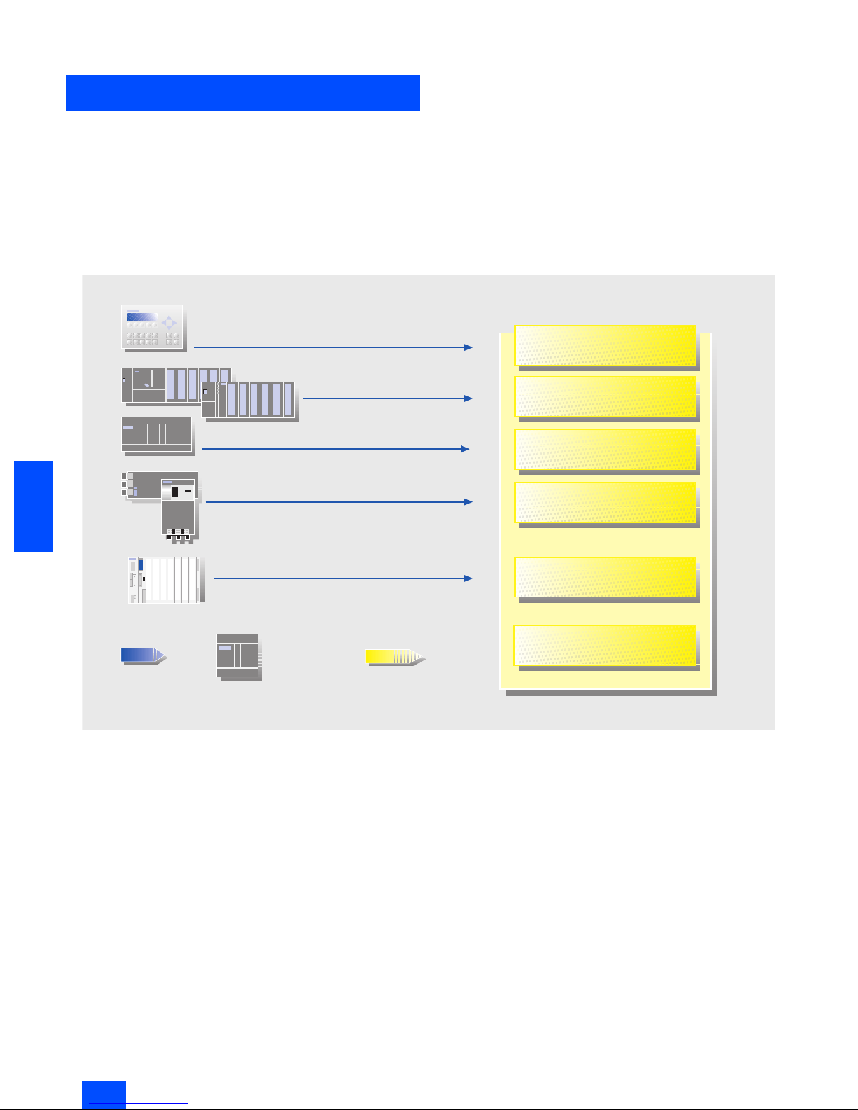
AS-Interface master for SIMATIC
0
1
Integrated interface
CP 343-2
CP 243-2
CP 142-2
CP 2430
C7-621 ASi
S5-115U to 155U
ET 200M
S7-200
ET 200X
S7-300
G_IK10_XX_20009
DP/AS-Interface Link 20E
Links
CP 343-2 P

Siemens IK PI · 2004
6/5
AS-Interface
Introduction
Technical specifications
6
■
Technical specifications
■
More information
Please note the operating framework conditions in each case for
the specified SIMATIC NET products (Order No. 6GK..., 6XV1...),
which you will find on the Internet page listed below.
Additional information is available in the Internet under:
http://www.siemens.de/simatic-net/ik-info
Standard EN 50295
Topology
Bus, star or tree topology
(like electrical installation)
Transmission medium
Unshielded two-wire cable
(2 x 1.5 mm
2
) for data and
auxiliary power
Connection method
Contacting of the AS-Interface
cable using the insulation
displacement method
Permissible cable length max.
100 m w/o repeater/extender
500 m range with repeater/
extender (parallel connection
of repeaters)
Cycle time max.
5 ms with full expansion,
10 ms using A/B method
Number of stations max.
31 slaves accord. to Complete
AS-Interface Spec. V2.0 ;
62 slaves accord. to Complete
AS-Interface Spec. V2.1
(A/B method),
integrated analog value
transmission
Number of binary
sensors/actuators
Max. 124 I/124 O
modules according to spec. V2.0;
Max. 248 I/186 O
modules according to spec. V2.1
Access procedure
Cyclical master-slave polling
method, cyclical acceptance
by host (PLC, PC)
Error correction
Identification and repetition of
faulty messages
Siemens IK PI · 2004
6/6
AS-Interface
A/B technique
6
■
Overview
The A/B technique concept
The AS-Interface specification 2.1 allows a doubling of network
stations from 31 to 62. The 31 addresses that can be assigned
in an AS-Interface network can be split into two mutually independent sub-addresses, e.g. in 1A and 1B.
If this is utilized for all 31 slaves, up to 62 slaves can be connected within an AS-Interface network. The so-called A/B slaves
can each have up to four inputs and three outputs.
Another new feature of the new AS-Interface specification V2.1
is integrated analog value transfer. In this case, integrated
means that no special function blocks are required in order to
access the analog values. Accessing data is therefore just as
easy in the case of analog values as it is with digital values. Integrated analog value transfer can be used with analog slaves
that support Proifiles 7.3 and 7.4.
AS-Interface master
To operate A/B slaves in an AS-Interface network, master modules working according to the specification 2.1 must also be
used. The A/B technique is supported by the SIMATIC S7
masters and the DP/AS-Interface links from Siemens. To masters
that do not support specification 2.1, only standard and A slaves
can be connected.
The sub-address of A/B slaves is set to “A” by default.
Masters and slaves that are already working to the new specifi-
cation are identified accordingly in the catalog.
Addressing A/B slaves
A/B slaves can be addressed like standard slaves via all commercial AS-Interface addressing units conforming to specification 2.1. AS-Interface addressing units that do not conform to the
new specification 2.1 can readdress A/B slaves only as A slaves.
As far as addressing is concerned, an analog slave is like a standard slave. Up to 31 analog slaves can therefore be operated in
one AS-Interface segment.
Communication cycle
Standard slaves are polled in every cycle (max. cycle time:
5ms).
If only an A or B slave is installed at an address, this slave is also
polled in every cycle (max. cycle time: 5 ms).
If an A/B slave pair is installed at an address, slave A is polled in
one cycle, slave B in the next (max. cycle time: 10 ms).
If only standard and/or A slaves are installed in a network, the
cycle time is the same as for standard masters (max. cycle time:
5 ms).
■
Benefits
• Lower costs for masters and power supply units
• Enhanced decentralization in installations with numerous,
widely distributed signals
• Existing AS-Interface systems can be expanded further
G_IK10_XX_20020
Previously 31 nodes
Slave 1
with A/B slaves max. 62 nodes:
Mixed operation also permissible:
Slave 31
Slave 1A Slave 31B
Slave 1 Slave 31
Slave 1B Slave 31A
Slave 2A Slave 2B
Slave type Number of slaves Number of inputs Number of outputs
AS-Interface standard Standard slave Up to 31 31 x 4 = 124 31 x 4 = 124
AS-Interface version 2.1 A/B slave Up to 62 62 x 4 = 248 62 x 3 = 186
Siemens IK PI · 2004
6/7
AS-Interface
A/B technique
6
■
Selection and Ordering data
1) Start of delivery: approx. end of 2003.
Design Order No.
Master according to Specification 2.1
CP 243-2
Master for SIMATIC S7-200
6GK7 243-2AX01-0XA0
CP 343-2
Master for SIMATIC S7-300
6GK7 343-2AH00-0XA0
CP 343-2 P
master for SIMATIC S7-300
configuration with STEP 7
6GK7 343-2AH10-0XA0
DP/AS-Interface Link 20E
Gateway for transition from AS-Interface to PROFIBUS DP
6GK1 415-2AA01
A/B slaves
3RK2 200-0CQ20-0AA3
K45 compact module
• 4 inputs
- M12 connection
3RK2 200-0CQ20-0AA3
- M8 screw-type connection
3RK2 200-0CT20-0AA3
- M8 snap-on connection
3RK2 200-0CU20-0AA3
•2 x 2 inputs
3RK2 200-0CQ22-0AA3
• 3 outputs
3RK2 100-1EQ20-0AA3
• 2 outputs / 2 inputs 1)
3RK2 400-1BQ20-0AA3
3RK2 400-1HQ00-0AA3
K60 compact module
• 8 inputs /2 outputs
3RK2 400-1HQ00-0AA3
• 8 inputs
3RK2 200-0DQ00-0AA3
• 4 inputs/ 3 outputs
3RK2 400-1FQ03-0AA3
3RK2 200-0CE02-0AA2
Slimline S22.5
• 4 inputs
- Screw-type terminals 1)
3RK2 200-0CE02-0AA2
- Cage Clamp terminals 1)
3RK2 200-0CG02-0AA2
3RK2 400-1FE00-0AA2
Slimline S45
• 4 inputs/ 3 outputs
- Screw terminals
3RK2 400-1FE00-0AA2
- Cage Clamp terminals
3RK2 400-1FG00-0AA2
Siemens IK PI · 2004
6/8
AS-Interface
Introduction
AS-Interface Safety at work
6
■
Overview
Safety included
The Safety at Work concept supports the direct integration of
components with relevance for safety, such as emergency stop
switches, protective cover switches or safety light barriers, in the
AS-Interface network. These are fully compatible with the familiar
AS-Interface components (masters, slaves, power supply units,
repeaters, etc.) in accordance with EN 50295 and are operated
in conjunction with them on the yellow AS-i cable.
The signals from the safety sensors are evaluated by a safety
monitor. This not only monitors the switching signals of the safety
sensors but also continuously checks that data is being transferred correctly. The safety monitor has one or two release circuits in a two-channel configuration which can be used to bring
the machine or installation into a safe state. Sensors and monitors can be connected at any point on the AS-Interface network.
It is also possible to use several monitors in the same network.
A failsafe controller or a special master is not necessary. The
master handles safety slaves in the same manner as all other
slaves and only receives the safety data for information purposes. They can therefore be used to expand any existing
AS-Interface network.
Safety at Work guarantees a maximum response time of 40 ms.
This is the time between application of the signal to the input of
the safe slave and switching off the output at the safety monitor.
Tested safety
The system has been tested and approved by the German
Technical Inspectorate (TÜV). The transmission technique for
signals with relevance for safety is designed to allow applications to be implemented up to category 4 in accordance with
EN 954-1.
Software
The safety-related applications can be configured using the
configuration software and then transferred into the monitor.
Moreover, the software can also be used for online diagnostics.
■
Benefits
• A failsafe PLC or special master is not required.
• Simple system structure due to standardized AS-Interface
technique.
• Safe and non-safe data on the same bus.
• Existing systems can be expanded quickly and easily.
• Safe signals can be combined in groups.
• Integration of the safety signals in the plant diagnostics concept.
• Approved up to category 4 acc. to EN 954-1.
• Safety at Work is certified by the German Technical Inspectorate (TÜV).
■
Application
Integrated safety systems using AS-Interface can be used in applications for which EMERGENCY-STOP pushbuttons, protective
door locks, Stop category 0 and 1, two-handed operation and
light arrays are currently installed.
■
Design
The safety system is constructed in the same manner as the now
familiar installation of AS-Interface.
The family of safe AS-Interface products comprises the safety
monitor that monitors the safe stations. The spectrum of safe stations comprises the safe modules and the safety-related sensors
with an integrated interface.
■
Function
Following a master call, the safe stations transmit their information, like the standard stations, to the master. The safety monitor
monitors this transfer from the safe stations to the master and
switches
• to the EMERGENCY-STOP status (in the case of faults in safe
stations) or
• to the safe status (in the case of a wire break).
The safety monitor is configured using software. The configuration comprises the input signals of the safe stations and the internal functions of the safety monitor. The safety monitor offers
OR logic, AND logic, timer functions, buffer storage, etc.
■
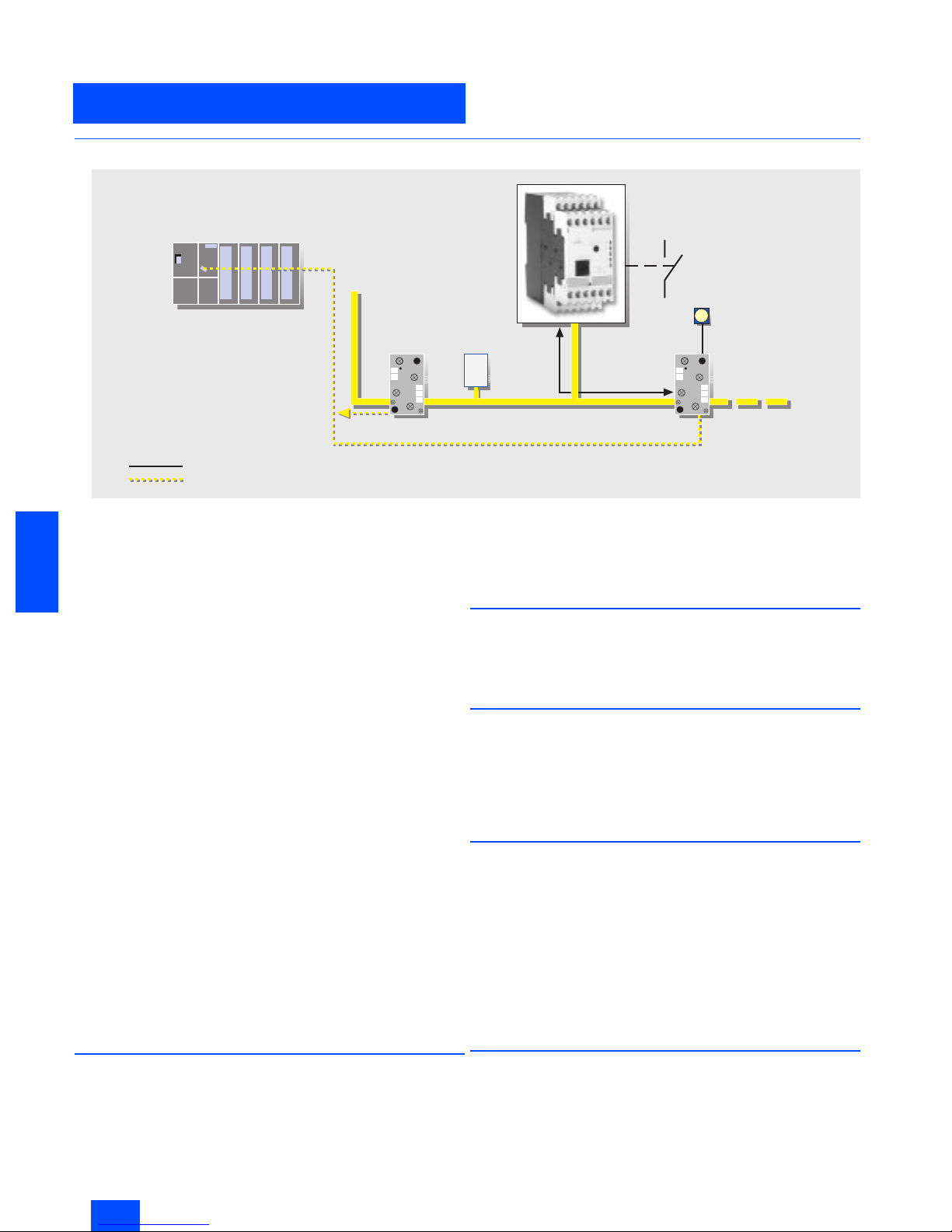
Integration
For integration of the safety system into AS-Interface, the existing infrastructure such as the master and the power supply unit
can continue to be used. For the safety system, the safety monitor is integrated as a monitoring component and the safe station
is integrated as the interface between the safe sensors and the
system. The safe sensors can be used as before.
G_IK10_XX_20021
Standard PLC
Standard master
Standard slave
Security monitor
Secure slave
with EMERGENCY-OFF
Signal evaluation of secure slave/security monitor
Master information (through regular I/O transfer)
Power section
Siemens IK PI · 2004
6/9
AS-Interface
AS-Interface Safety at work
AS-Interface safety monitors
6
■
Overview
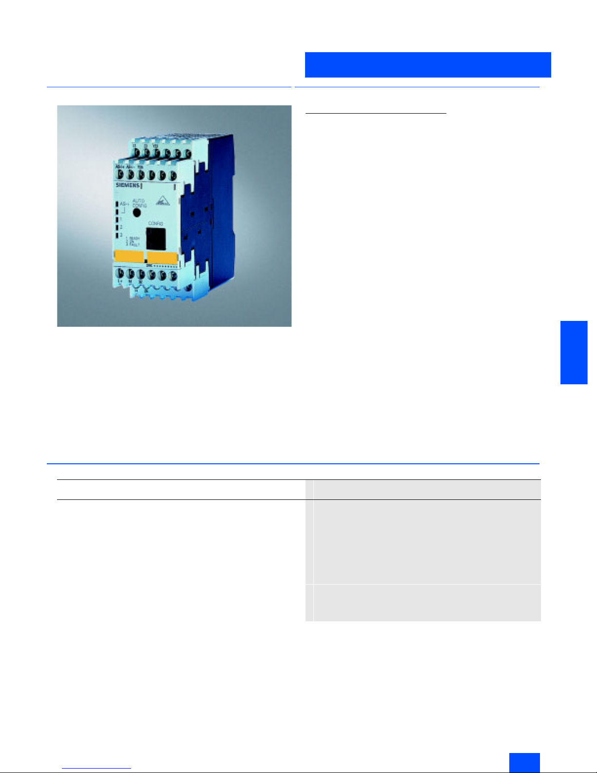
The safety monitor is the core component of Safety at Work. A
safe application is configured with a PC via the safety monitor.
Various different application-specific operating modes can be
used. These include the EMERGENCY-STOP function, tumbler,
two-handed operation as well as selection of Stop category
0 or 1.
In order to fully utilize the AS-Interface diagnostic capability, the
monitor can also be operated with AS-Interface addresses as an
alternative.
Two versions of the monitor are available:
• Safety monitor with one two-channel release circuit
• Safety monitor with two two-channel release circuits
■
Function
Safety monitor with enlarged functions
Logical OR operation
In this logical operation up to six elements can be OR gated.
(Until now, only two elements could be OR gated).
Logical AND operation
In addition to the standard AND gating in the main path of an
enabling circuit, an AND operation can be inserted into an OR
operation. More than two elements can be gated in this AND.
Buffer
Temporary shutdowns are stored in a buffer for the purpose of
diagnostics.
Number of devices
The number of devices that the safety monitor can process has
been increased from 32 to 48. Applications that are larger and
more complex can now be simulated in the safety monitor.
Timer functions
Timers are offered with the functions
• Delayed switching-on
• Delayed switching-off and
• Pulse.
Compatibility
Any configurations that have been previously created can be
loaded into the "new" safety monitor without changes.
■
Technical specifications
Safety monitor
3RK1 105
Rated operational current
•Ie/AC-12 up to 250 V, 2 A
•I
e
/AC-15 115 V, 2A
230 V, 2A
•I
e
/DC-12 up to 24 V, 3 A
•I
e
/DC-13 24 V, 1 A
115 V, 0.1 A
230 V, 0.05 A
• Response time
< 40 ms
• Ambient temperature in °C
0 to +60
• Storage temperature in °C
-40 to +85
Siemens IK PI · 2004
6/10
AS-Interface
AS-Interface safety monitors
AS-Interface Safety at work
6
■
Selection and Ordering data
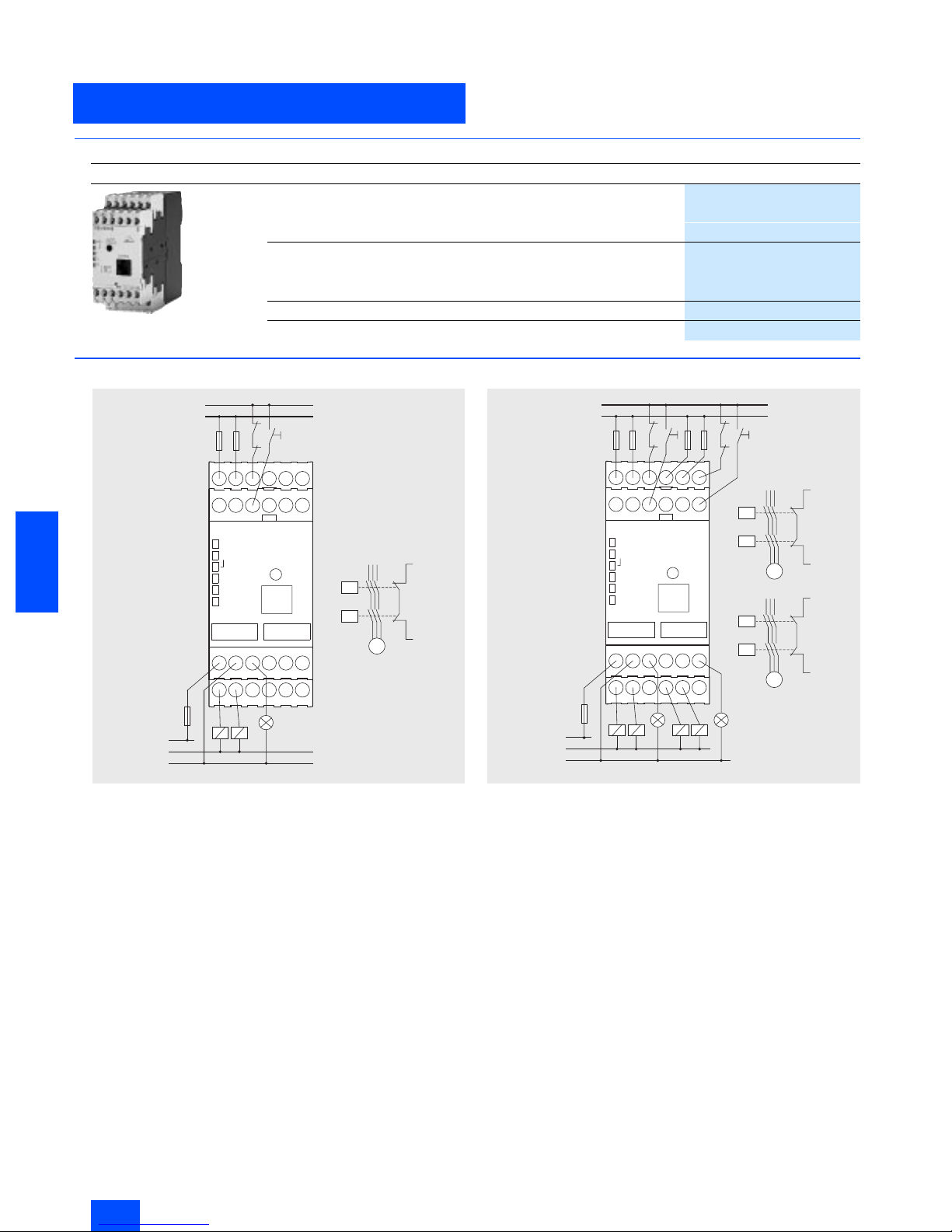
■
Dimensional drawings
Safety monitor with one release circuit
Safety monitor with two release circuits
Design
Order No.
Safety monitor
Safety monitor
• One enabling circuit
3RK1 105-1AE04-0CA0
• Two enabling circuits
3RK1 105-1BE04-0CA0
Safety monitor with extended functionality
• One enabling circuit
3RK1105-1AE04-2CA0
• Two enabling circuits
3RK1105-1BE04-2CA0
Configuration software
3RK1 802-2FB06-0GA0
Cable set
3RK1 901-5AA00
L/+
L
K1
K2
Start 1
1.13 1.23 1.Y1
AS-i+AS-i-
1.Y2
AS-i
1
2
3
L+ M 1.32
1.14
1.24
PE
K1 K2
L+
M/N
M
K1
K2
M
L+
1.Y1
g_nsa0_xx_00356
L/+
L
Start 2
Start 1
K1
K2
K3
K4
1.13 1.23 1.Y1
AS-i+ AS-i- 1.Y2
AS-i
1
2
3
K1
K2
L+ M 1.32 2.32
1.14 1.24 PE 2.14 2.24
K1
K2 K3 K4
L+
M/N
M
L/+
1.Y1
M
K3
K4
L/+
M
2.Y1
g_nsa_xx_00357
Siemens IK PI · 2004
6/11
AS-Interface
AS-Interface Safety at work
AS-Interface safe compact modules
6
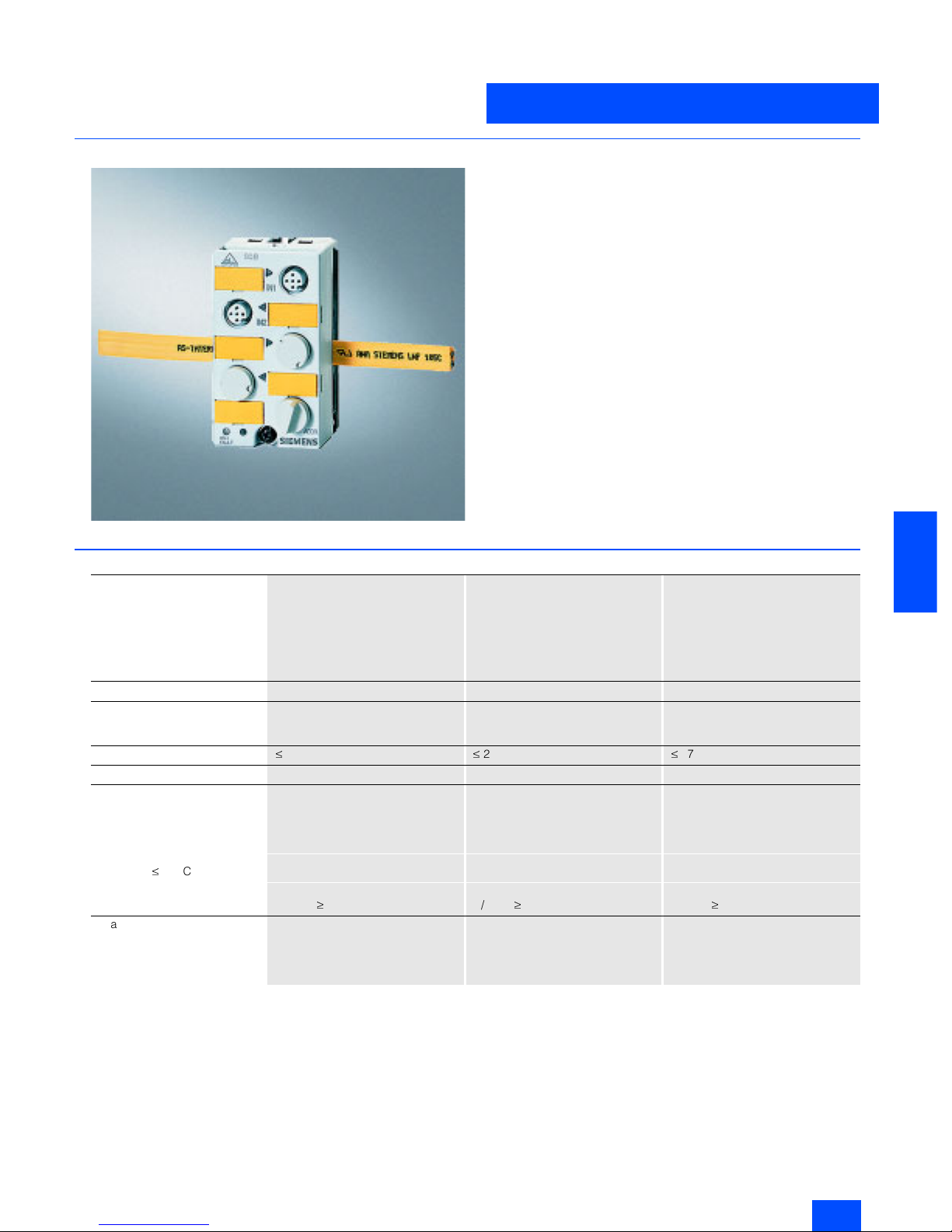
■
Overview
The compact module product family will be supplemented with
safe modules:
• The K45F safe compact module is equipped with two "safe" inputs. For operation up to category 2 acc. to EN 954-1, each input can be separately assigned. If category 4 is required, a
two-channel input is available on the module.
• The K60F safe compact module has, in addition to the two safe
inputs, also two standard outputs.
■
Technical specifications
K45F safe compact module K60F safe compact module K60F safe compact module
PNP transistor PNP transistor PNP transistor
Standard assignment Standard assignment Standard assignment
2 safe inputs 2 safe inputs,
2 standard outputs
2 safe inputs,
2 standard outputs with U
Aux
3RK1 205-0BQ00-0AA3 3RK1 405-0BQ00-0AA3 3RK1 405-0BQ00-0AA3
AS-Interface chip
SAP 4 SAP 4 SAP 4
Operational voltage
in accordance with AS-Interface
specification in V
26.5 to 31.5 26.5 to 31.5 26.5 to 31.5
Total current input in mA
£
45
£
270
£
270
Input connection
PNP PNP PNP
Inputs
• Sensor supply via AS-Interface -- -- --
•Sensors
Mechanical switching contact Mechanical switching contact Mechanical switching contact
• Voltage range in V
-- -- --
• Current carrying capacity for all
inputs (T
u
£
40 °C) in mA
-- -- --
• Switching level High in V
Contact open/closed Contact open/closed Contact open/closed
• Input current Low/High in mA
- / /
peak
³ 5 - / /
peak
³ 5 - / /
peak
³ 5
Pin assignment inputs
Pin1 and 2 = Terminal/switching
contact
Pin3 and 4
Terminal/switching contact
Pin5 = Not assigned
Pin1 and 2 = Terminal/switching
contact
Pin3 and 4
Terminal/switching contact
Pin5 = Not assigned
Pin1 and 2 = Terminal/switching
contact
Pin3 and 4
Terminal/switching contact
Pin5 = Not assigned

Siemens IK PI · 2004
6/12
AS-Interface
AS-Interface safe compact modules
AS-Interface Safety at work
6
■
Technical specifications (continued)
Outputs
• Type of output -- Electronics Electronics
• Current carrying capacity
DC 12/13 in A
-- 2 --
• Current carrying capacity typ.
(max. 4 A per module) in A
-- Max. 0.18 Max. 4
• Pin assignment outputs
-- 3 = "–"
4 = Output
5 = Earth connection
3 = "–"
4 = Output
5 = Earth connection
• Short-circuit protection
-- Built-in Built-in
• Inductive interference protection (free-wheeling diode)
-- None Built-in
• External voltage supply
24 V DC
-- -- Via black AS-Interface flat cable
• Watchdog
-- Built-in Built-in
I/O configuration
0 7 7
ID/ID2 code
B B B
Assignment of data bits
• Socket 3 and 4 Not assigned (closed) Not assigned (closed) Not assigned (closed)
• Socket 5
Not assigned (closed) Pin 4 = OUT1 (D0)
Pin 2 = Not assigned (closed)
Pin 4 = OUT1 (D0)
Pin 2 = Not assigned (closed)
• Socket 6
Not assigned (closed) Pin 4 = OUT2 (D1)
Pin 2 = Not assigned (closed)
Pin 4 = OUT2 (D1)
Pin 2 = Not assigned (closed)
• Socket 7 and 8
Not assigned (closed) Not assigned (closed) Not assigned (closed)
AS-Interface certificate
Ye s Yes Yes
Approvals
UL, CSA UL, CSA UL, CSA
Degree of protection
IP67 IP67 IP67
Earth connection
-- PIN 5 of each M 12 socket is
connected to the grounding plate in
the mounting plate via a pin
(outputs only sockets 5 and 6).
PIN 5 of each M 12 socket is
connected to the grounding plate in
the mounting plate via a pin
(outputs only sockets 5 and 6).
Ambient temperature in °C
-25 to +85 -25 to +85 -25 to +85
Storage temperature in °C
-40 to +85 -40 to +85 -40 to +85
Number of I/O sockets
2 4 4
Status indication
• I/O display Yellow LED Yellow LED Yellow LED
• U
Aux
-- -- Green LED
• AS-Interface/diagnostics
display
Green/red LED Green/red LED Green/red LED
Connection
via mounting plate for K45 compact
module
via mounting plate for K60 compact
module
via mounting plate for K60 compact
module
Addressing
Front addressing socket,
after the 15th addressing,
the module keeps the last address
Front addressing socket,
after the 15th addressing,
the module keeps the last address
Front addressing socket,
after the 15th addressing,
the module keeps the last address
Siemens IK PI · 2004
6/13
AS-Interface
AS-Interface Safety at work
AS-Interface safe compact modules
6
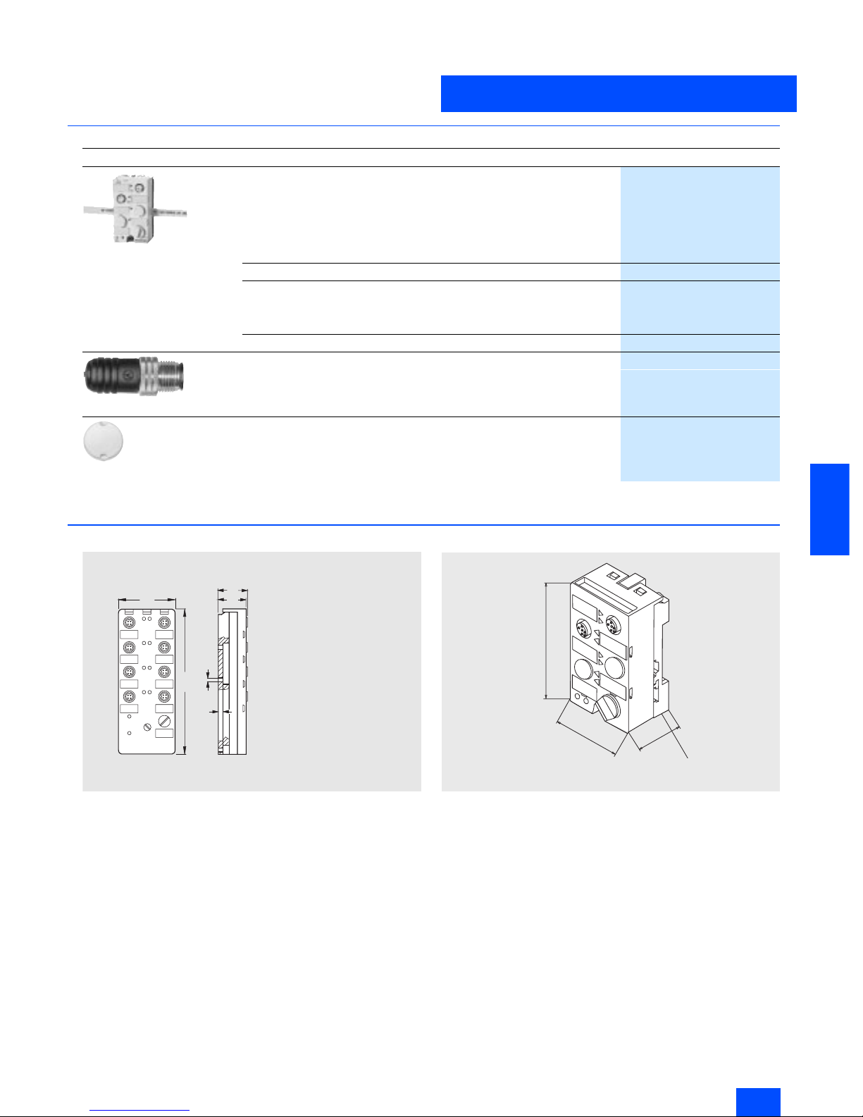
■
Selection and Ordering data
1) Modules supplied without mounting plate.
■
Dimensional drawings
K60F safe module
K45F safe module
Design
Order No.
3RK1 205-0BQ00-0AA3
K45F safe compact module
1)
2FE
3RK1 205-0BQ00-0AA3
K45 mounting plate
3RK1 901-2EA00
K60F safe compact module
1)
• 2FE/2A
3RK1 405-0BQ00-0AA3
• 2FE/2A with U
Aux
3RK1 405-1BQ00-0AA3
K60 mounting plate
3RK1 901-0CA00
3RK1 901-1AA00
Input bridge for K45/K60F
• Black version
3RK1 901-1AA00
• Red version
3RK1 901-1AA01
3RK1 901-1KA01
AS-Interface M12 sealing caps, protected against manipulation
For spare M12 sockets
(one packing contains ten sealing caps)
3RK1 901-1KA01
N S A 0 _ 0 0 0 2 6
Æ
4 , 5
3 1
2 9
5
1 5 2
6 0
S i d e v i e w w i t h
m o u n t i n g p l a t e
3 R K 1 9 0 1 - 0 C A 0 0
45
80
30
Mounting plate
3RK1901-2EA00
Siemens IK PI · 2004
6/14
AS-Interface
AS-Interface safe compact modules
AS-Interface Safety at work
6
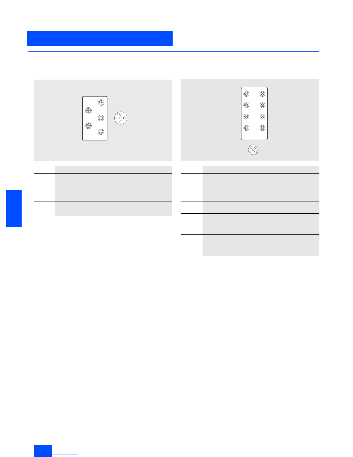
■
Schematics
Logical assignments
K45F Safe Compact Module
If only one single-channel switch will be connected to the module, this must be connected to Channel 1. The second channel
must be bridged. This can be performed with the M12 connector
3RK1901-1AA00 on Socket 2.
Pin 3 of Socket 1 is connected to Pin 1 of Socket 2 and Pin 4 of
Socket 1 is connected to Pin 2 of Socket 2. If both socket pairs
are assigned, the inputs are linked.
K60F Safe Compact Module
Pin 3 of Socket 1 is connected to Pin 1 of Socket 2 and Pin 4 of
Socket 1 is connected to Pin 2 of Socket 2. If both socket pairs
are assigned, the inputs are linked.
Socket Assignment / data sheet / function
1
Pin 1 and Pin 2: affects bits D0 and D1 = Channel 1
Pin 3 and Pin 4: affects bits D2 and D3 = Channel 2
Pin 5 not assigned
2
Pin 1 and Pin 2: affects bits D2 and D3 = Channel 2
Pin 5 not assigned
3
Unused
4
Unused
²
1
2
3
4
ADDR
1
2
3
4
G_NSA0_XX_00355
Socket Assignment / data sheet / function
1
Pin1 and Pin 2: affects bits D0 and D1 = Channel 1
Pin 3 and Pin 4: affects bits D2 and D3 = Channel 2
Pin 5: unused
2
Pin 1 and Pin 2: affects bits D2 and D3 = Channel 2
Pin 5: unused
3/4/7 and
8
Not assigned, factory sealed
5
Pin 4: Output 1
Pin 3: -Pin 5: Ground
Pin 1 and Pin 2: unused
6
Pin 4: Output 2
Pin 3: -Pin 5: Ground
Pin 1 and Pin 2: unused
3
4
2
N S A _ 0 0 3 5 8
1
3
7
5
1
4
8
6
2
Siemens IK PI · 2004
6/15
AS-Interface
AS-Interface Safety at work
AS-Interface position switches
6
■
Overview
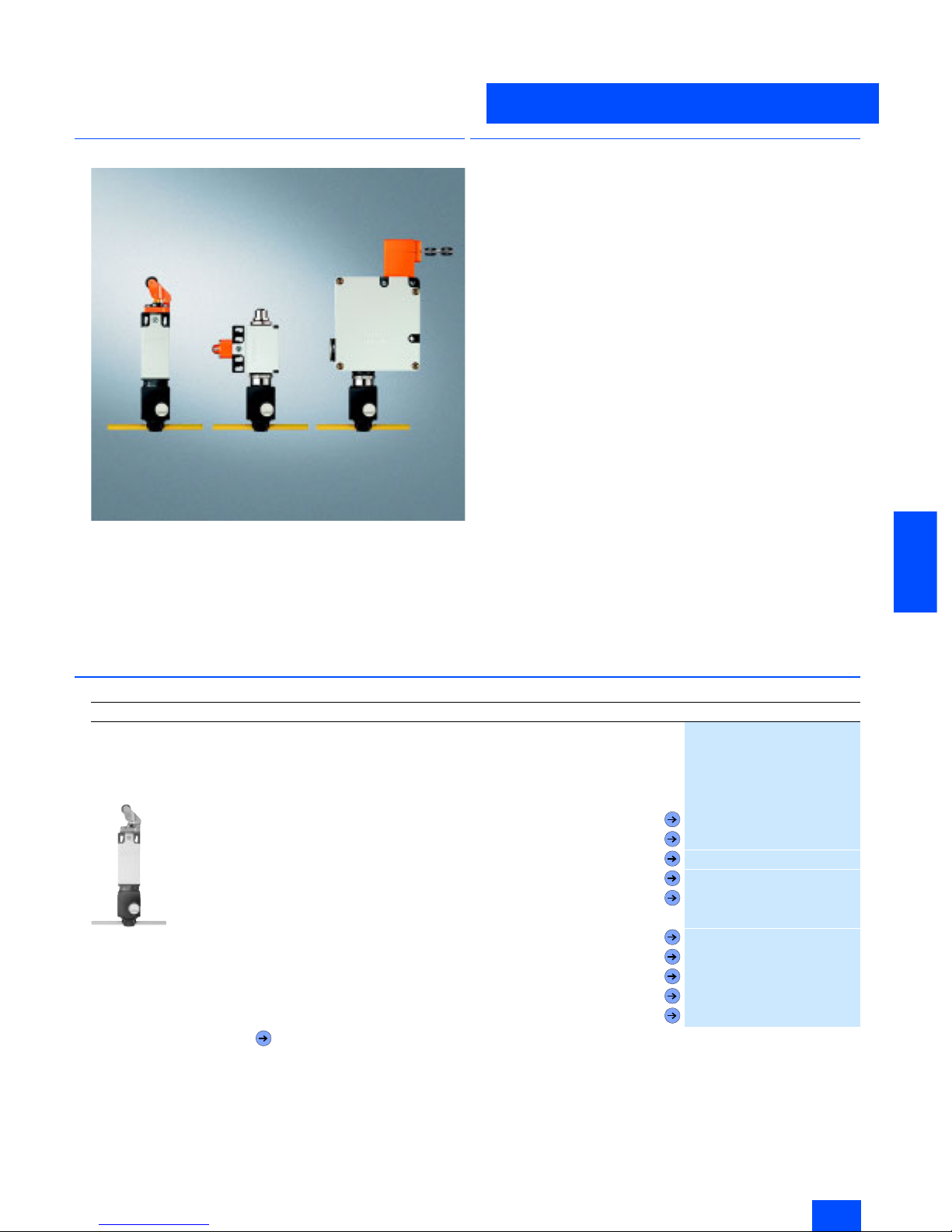
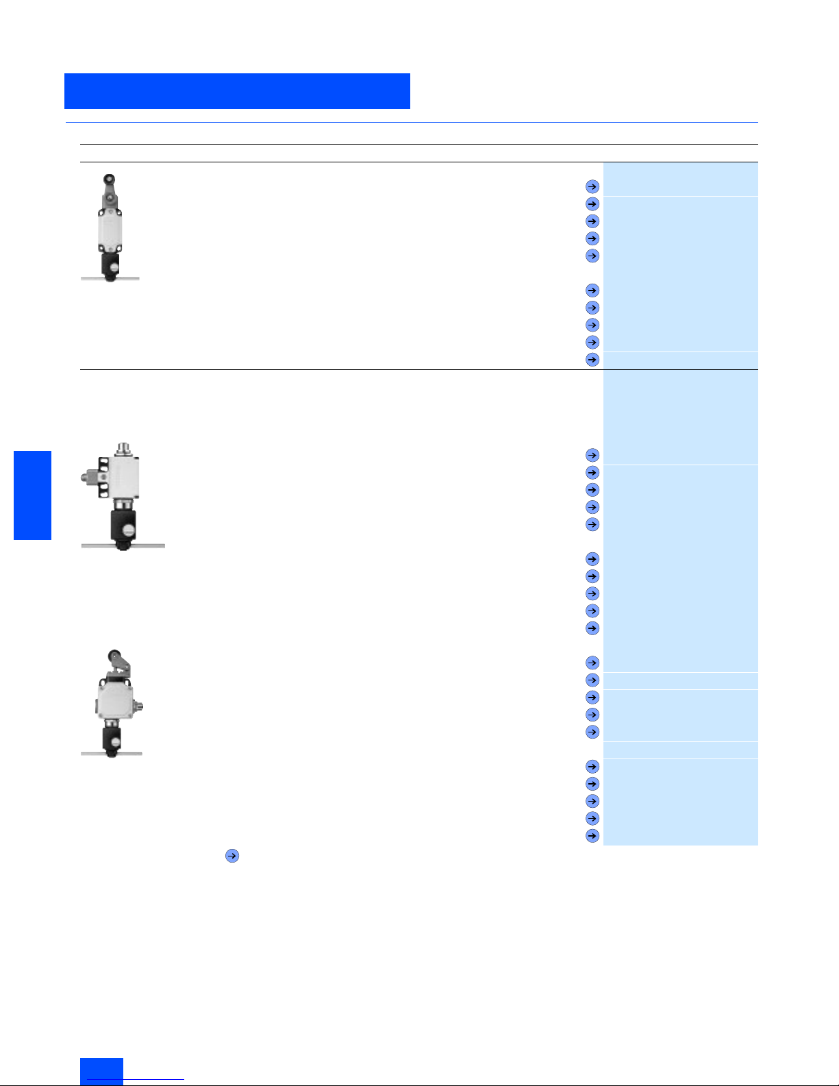
Position switch from left to right:
Standard / Standard, with M12 connector / with tumbler
It is also possible now to directly connect SIGUARD position
switches via the standard AS-Interface with safety-oriented communication. In this case, the safety functions no longer have to
be conventionally wired up.
Position switches convert the mechanical positions of moving
machine components into electrical signals.
■
Application
Position switch with separate actuator
The position switches with separate actuator are used in applications in which the position of doors, covers or guards has to
be monitored for safety reasons.
The position switch can only be switched using the associated
coded actuator. It is not possible to bypass it manually or using
a tool.
Position switch with tumbler
The position switches with tumblers are special safety devices
that prevent the inadvertent or intentional opening of protective
doors, guards or other covers when a dangerous state exists,
e.g. for coastdown movements of the switched-off machine.
The safety switch with tumbler has two main tasks:
• Enabling the machine when the protective device is closed
and locked
• Disabling the machine when the protective device is open
The position switch can only be switched using the associated
coded actuator. It is not possible to bypass it manually or using
a tool.
■
Selection and Ordering data
Design
Order No.
AS-Interface position switch, standard
Via AS-Interface F adaptor
With direct connection of AS-Interface to Safety at Work
For use up to Category 2 acc. to EN 954-1
IP65
3SF3 200-6EV00-0BA1
• Molded plastic enclosure, EN 50 047, 31 mm wide, slow-action contact, two NC
- Overtravel plunger
3SF3 200-6CV00-0BA1
- Roller plunger
3SF3 200-6DV00-0BA1
- Roller lever
3SF3 200-6EV00-0BA1
- Angular roller lever
3SF3 200-6FV00-0BA1
- Swivel lever
3SF3 200-6GV00-0BA1
• Molded plastic enclosure, EN 50 047, 31 mm wide, snap action contact, one NC
- Overtravel plunger
3SF3 200-1CV00-0BA1
- Roller plunger
3SF3 200-1DV00-0BA1
- Roller lever
3SF3 200-1EV00-0BA1
- Angular roller lever
3SF3 200-1FV00-0BA1
- Swivel lever
3SF3 200-1GV00-0BA1
Forced opening IEC 60947-5-1, Appendix K.
Siemens IK PI · 2004
6/16
AS-Interface
AS-Interface position switches
AS-Interface Safety at work
6
■
Selection and Ordering data (continued)
Design
Order No.
3SF3 120-6GW00-0BA1
• Metal enclosure, EN 50 041, 40 mm wide, slow-action contact, two NC
- Overtravel plunger
3SF3 120-6CV00-0BA1
- Roller plunger
3SF3 120-6DV00-0BA1
- Roller lever
3SF3 120-6EV00-0BA1
- Angular roller lever
3SF3 120-6FV00-0BA1
- Swivel lever
3SF3 120-6GW00-0BA1
• Metal enclosure, EN 50 041, 40 mm wide, snap action contact, one NC
- Overtravel plunger
3SF3 120-1CV00-0BA1
- Roller plunger
3SF3 120-1DV00-0BA1
- Roller lever
3SF3 120-1EV00-0BA1
- Angular roller lever
3SF3 120-1FV00-0BA1
- Swivel lever
3SF3 120-1GW00-0BA1
AS-Interface position switch, standard, with M12 connector
M12 connector for connecting an additional position switch
Direct connection of AS-Interface to Safety at Work
For use up to Category 4 acc. to EN 954-1
IP65
3SF3 210-0DV00-0BA2
• Molded plastic enclosure, EN 50 047, 50 mm wide, slow-action contact, 1 NC
- Overtravel plunger
3SF3 210-0CV00-0BA2
- Roller plunger
3SF3 210-0DV00-0BA2
- Roller lever
3SF3 210-0EV00-0BA2
- Angular roller lever
3SF3 210-0FV00-0BA2
- Swivel lever
3SF3 210-0GV00-0BA2
• Molded plastic enclosure, EN 50 047, 50 mm wide, snap-action contact, 1 NC
- Overtravel plunger
3SF3 210-1CV00-0BA2
- Roller plunger
3SF3 210-1DV00-0BA2
- Roller lever
3SF3 210-1EV00-0BA2
- Angular roller lever
3SF3 210-1FV00-0BA2
- Swivel lever
3SF3 210-1GV00-0BA2
3SF3 100-0EV00-0BA2
• Metal enclosure, EN 50 041, 56 mm wide, slow-action contact, 1 NC
- Overtravel plunger
3SF3 100-0CV00-0BA2
- Roller plunger
3SF3 100-0DV00-0BA2
- Roller lever
3SF3 100-0EV00-0BA2
- Angular roller lever
3SF3 100-0FV00-0BA2
- Swivel lever
3SF3 100-0GW00-0BA2
• Metal enclosure, EN 50 041, 56 mm wide, snap-action contact, 1 NC
- Overtravel plunger
3SF3 100-1CV00-0BA2
- Roller plunger
3SF3 100-1DV00-0BA2
- Roller lever
3SF3 100-1EV00-0BA2
- Angular roller lever
3SF3 100-1FV00-0BA2
- Swivel lever
3SF3 100-1GW00-0BA2
Forced opening IEC 60947-5-1, Appendix K.
Siemens IK PI · 2004
6/17
AS-Interface
AS-Interface Safety at work
AS-Interface position switches
6
■
Selection and Ordering data (continued)
1) 1) Accessories, technical data, contact travel, circuit diagrams and
dimensional drawings for the specified basic switch can be found in
the Catalog LV 10, Edition 2004, Section AS-Interface Safety Systems.
Design
Order No.
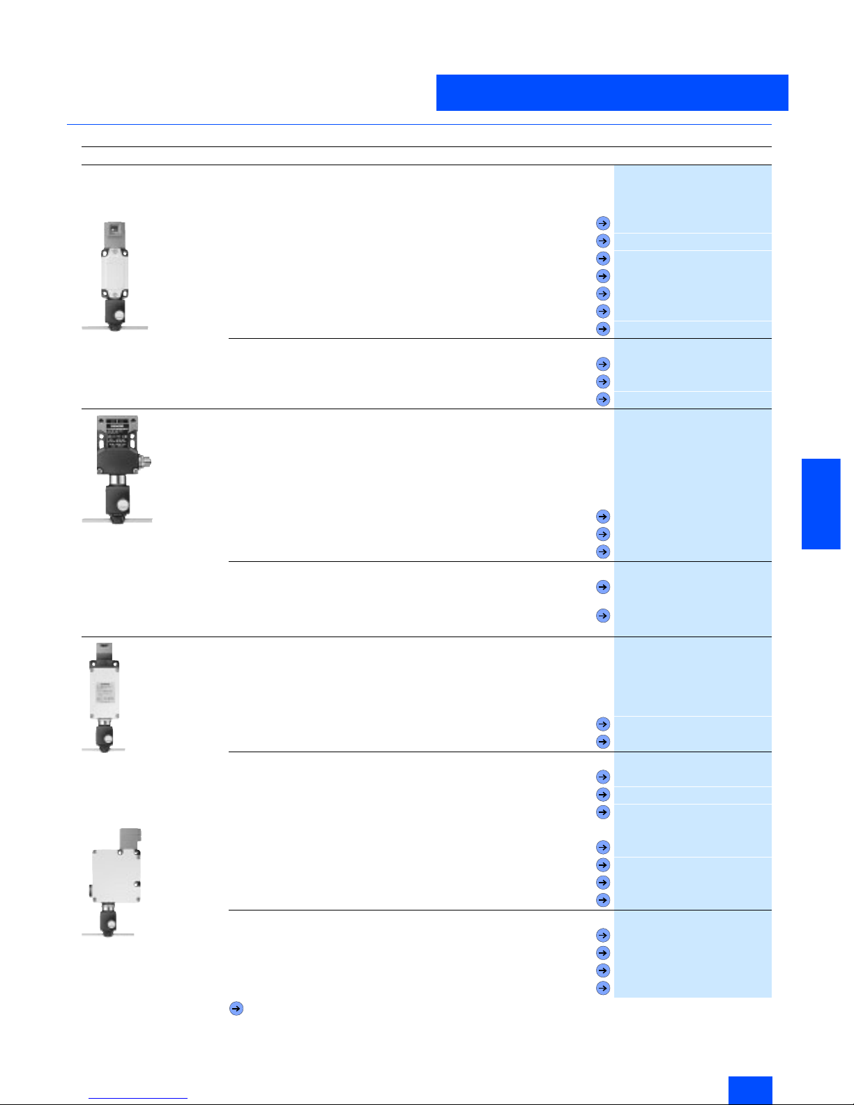
AS-Interface position switch, with separate actuator
With direct connection of AS-Interface to Safety at Work
For use up to Category 2 acc. to EN 954-1
IP65, Slow-action contact, 2 NC
• Molded plastic enclosure, side operation, fixing acc. to EN 50 047
3SF3 200-6XX03-0BA1
• Molded plastic enclosure, front operation, fixing acc. to EN 50 047
3SF3 200-6XX04-0BA1
• Molded plastic enclosure, side and front operation, 52 mm wide
- 30 N extraction force
3SF3 243-0XX00-0BA1
- 5 N extraction force
3SF3 243-0XX40-0BA1
- Automatic ejection
3SF3 243-0XX30-0BA1
• Metal enclosure, fixing acc. to EN 50 041
3SF3 120-6XX00-0BA1
Actuator
• Standard, Width/length of enclosure 79 mm
3SX3 197
• With crosswise fixing, Width/length of enclosure 50 mm
3SX3 206
• Universal radius, Width/length of enclosure 80 mm
3SX3 203
3SF3 257-6XX00-0BA2
AS-Interface position switch with separate actuator and M12 connector
M12 connector for connecting an additional position switch
Direct connection of AS-Interface to Safety at Work
For use up to Category 4 acc. to EN 954-1
IP65, Slow-action contact, one NC
Molded plastic enclosure
Side and front operation
52 mm wide
• 30 N extraction force
3SF3 257-6XX00-0BA2
• 5 N extraction force
3SF3 257-6XX40-0BA2
• Automatic ejection
3SF3 257-6XX30-0BA2
Actuator
• Standard, Width/length of enclosure 27 mm
(r
min
= 150 mm)
3SX3 218
• Universal radius, Width/length of enclosure 33 mm
(r
min
= 45 mm)
3SX3 228
3SF3 750-6XX00-0BA1
AS-Interface position switch, with separate actuator and tumbler
With direct connection of AS-Interface to Safety at Work
For use up to Category 4 acc. to EN 954-1
IP65, Pg 13.5, Solenoid voltage 24 V DC
Monitoring of actuator and solenoid position
• Plastic housing
- Locking force 1200 N, locked by spring force
3SF3 760-6XX00-0BA1
- Locking force 1200 N, locked by magnetic force
3SF3 750-6XX00-0BA1
Actuator
•Standard,
3SX3 252
• with crosswise fixing
3SX3 253
•radius
3SX3 254
3SF3 830-6XX00-0BA1
• Metal housing
- Locking force 1200 N, locked by spring force
3SF3 860-6XX00-0BA1
- Locking force 1200 N, locked by magnetic force
3SF3 850-6XX00-0BA1
- Locking force 2000 N, locked by spring force
3SF3 840-6XX00-0BA1
- Locking force 2000 N, locked by magnetic force
3SF3 830-6XX00-0BA1
Actuator
• Standard, length 79 mm
3SX3 197
- for left approach direction, length 132 mm
3SX3 207
- with crosswise fixing, length 50 mm
3SX3 206
• Universal radius, length 80 mm
3SX3 203
Forced opening IEC 60947-5-1, Appendix K.
Siemens IK PI · 2004
6/18
AS-Interface
AS-Interface cable-operated switches
AS-Interface Safety at work
6
■
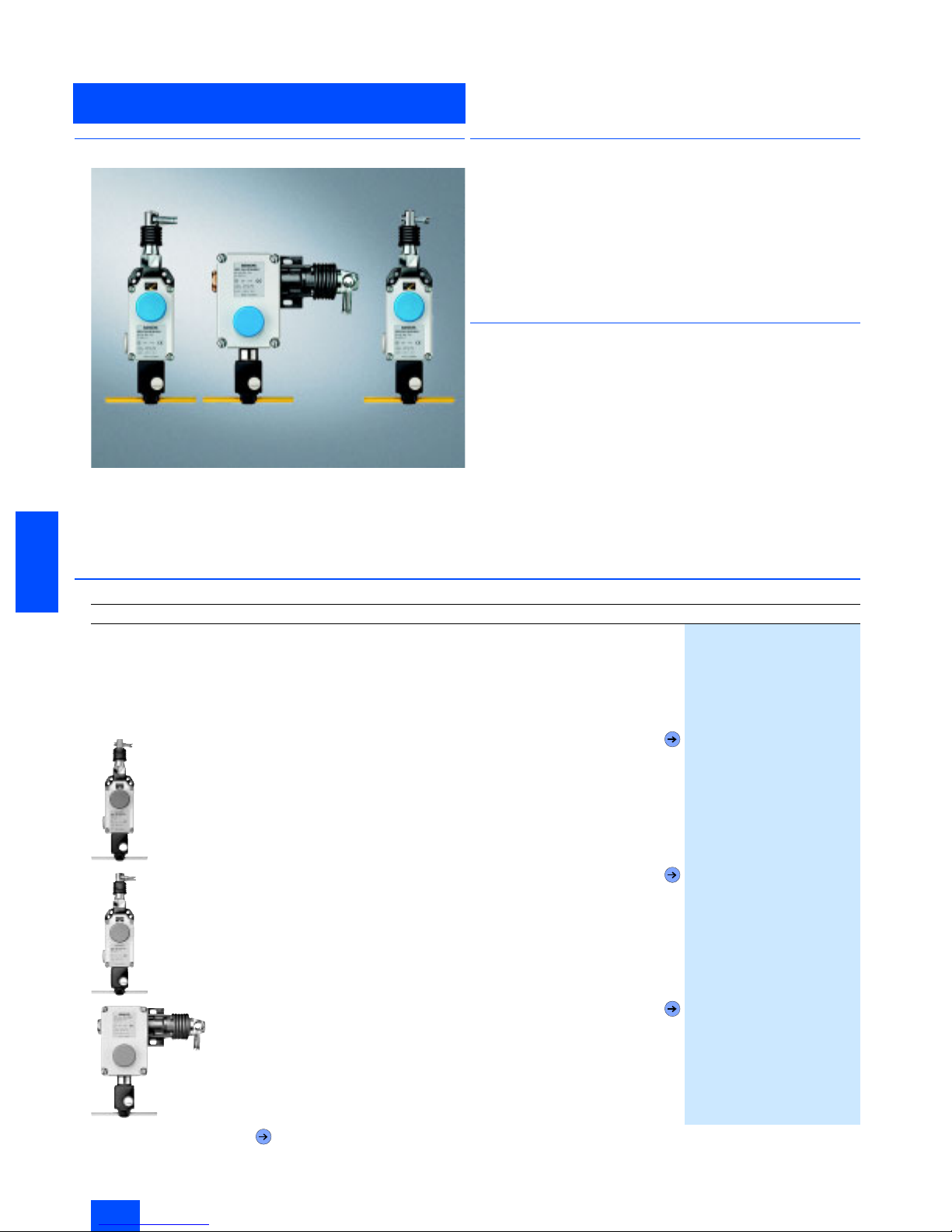
Overview
It is also possible to connect AS-Interface cable-operated
switches via the standard AS-Interface with safety-oriented communication.
In this case, the safety functions no longer have to be conventionally wired up.
■
Application
SIGUARD cable-operated switches are used for monitoring or
for EMERGENCY-STOP facilities on particulary endangered system sections.
As the effective range of a cable-operated switch is limited by
the length of the cord, large systems can also be protected.
Specifications
Switches with latching for implementation in EMERGENCY-STOP
equipment correspond to the EN 418 standard.
■
Function
The safety contacts of the AS-Interface cable-operated switch
are positively driven.
The AS-Interface cable-operated switches are ready to operate
after pretensioning of the pull-wire or the rope.
When the rope is pretensioned, it must be released before the
cable-operated switch can be returned to the original state.
■
Selection and Ordering data
1) Accessories, technical specifications, contact travel, circuit diagrams
and dimensional drawings are given for the specified basic switch in
Catalog LV 10 Section AS-Interface Safety Systems
Design
Order No.
AS-Interface cable-operated switch
With direct connection of AS-Interface to Safety at Work
Metal housing with dust protection
Implementable up to Category 4 to EN 954-1
IP65
Latching to EN 418
Pushbutton release
2 NC contacts
• For cable lengths up to 10 m,
with adjustment window
3SF2 120-1BF00-0BA1
• For cable lengths up to 25 m,
with adjustment window
3SF2 150-1BF00-0BA1
• For cable lengths up to 50 m
3SF2 140-1BF00-0BA1
Forced opening IEC 60947-5-1, Appendix K.
Siemens IK PI · 2004
6/19
AS-Interface
AS-Interface Safety at work
AS-Interface light curtains and light arrays
for Category 4
6
■
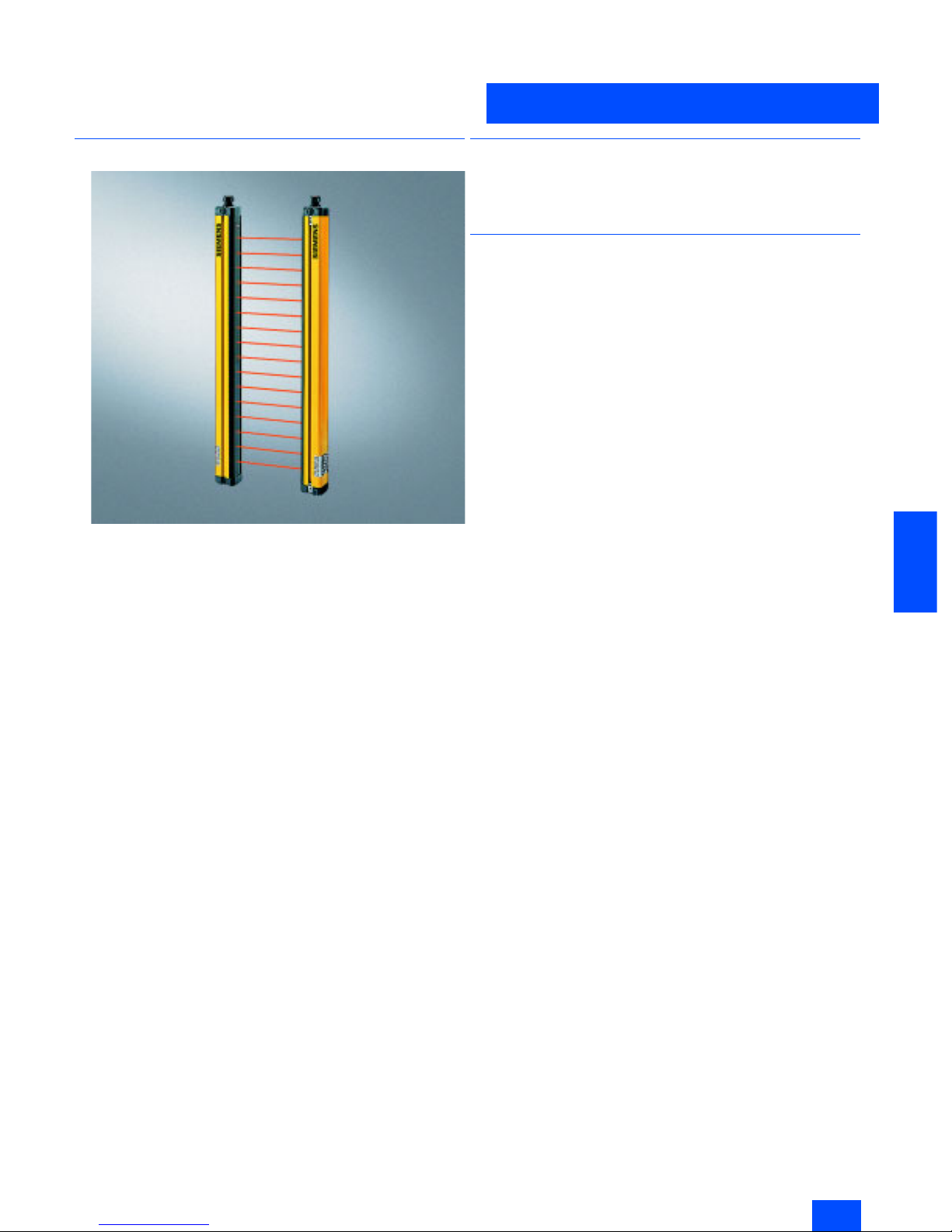
Overview
The light curtains and light arrays of Category 4 acc. to EN 9541 offer active optical protection for persons at machines. They
can be connected to AS-Interface directly and safely as an option.
SIGUARD light curtains and light arrays are
• active opto-electronic protective devices (AOPD),
• comply with Type 4 acc. to EN 61496-1, -2,
• are EU prototype-tested,
• protect the operating personel working on or near dangerous
machines,
• operate contact-free,
• are free of wear in comparison to mechanical systems (e.g.
safety mats).
For further details, see the manual "Safety Integrated“ and the
operating instructions for the respective devices.
■
Benefits
• Double-scan function
• Cascading of host and guest devices
• Two transmission channels
■
Design
A SIGUARD Light Curtain or light array comprises a transmitter
and a receiver that must be mounted opposite each other.
Depending on the resolution and length, a specific number of
transmit and receive diodes are arranged in a vertical row.
The infra-red LEDs of the transmitter send short light pulses that
are received by the receive diodes.
SIGUARD Light Curtains:
• Resolution 14, 30 and 50 mm,
• Length 150 mm to 3 m,
• Cascading of master and slave devices to create larger height
or length of protective zone or for angular arrangement.
SIGUARD Light Arrays:
• 2-, 3- or 4-beam for access protection.
Standards
• EN 61 496-1, -2, IEC 61 496-1, -2 (requirements for non-contact
protection systems)
• EN 999 (incl. calculation of safety clearances)
• EN 954-1 (safety of machines, safety-related parts of controls).

Siemens IK PI · 2004
6/20
AS-Interface
AS-Interface light curtains and light arrays
for Category 4
AS-Interface Safety at work
6
■
Technical specifications
1) From interruption of the protective zone to the cut-out command on AS-Interface
Technical specifications common to all AS-Interface light curtains and light arrays
Safety classification
Type 4 according to IEC 61496-1, -2 or EN 61496-1 (self-monitoring)
Height of protective zone in mm
150 to 1800 (for series with 14 and 30 mm resolution)
450 to 3000 (for series with 50 mm resolution)
750 to 3000 (for series with 90 mm resolution)
Width of protective zone,
sensing range in m
0.3 to 6 (for series with 14 mm resolution)
0.8 to 18 (for series with 30, 50 and 90 mm resolution as well as for light arrays)
0.6 to 60 (for light arrays)
Detection capability
14 mm, 30 mm, 50 mm or 90 mm or complete persons with 2, 3 or 4 beams
Response time of the
safety equipment in ms
1)
12 to 44, d-scan 15 to 83 (for 14 mm resolution)
12 to 25, d-scan 15 to 44 (for 30 mm resolution)
< 22, d-scan 38 (for 50 mm resolution)
< 18, d-scan 25 (for 90 mm resolution)
Response time of the
complete system
Response time 3SF7842 + response time of AS-Interface safety monitor (max. 40 ms)
Degree of protection
IP65
Supply current in mA
Max. 130 (transmitter)
Max 140 (receiver)
Operating mode
Protection mode without restart lockout
Transmitter/receiver synchronization
Optical synchronization, two transmission channels can be selected
Infra-red disturbance suppression
Two techniques for selection:
Standard = high suppression
d-scan = extremely high degree of suppression
Cross-section in mm
55 * 52
Length in mm
234 to 3084 (depending on height of protective zone)
Air humidity in %
15 to 95
Operating temperature in °C
0 to +55
Storage temperature in °C
-25 to +70
Supply voltage in V
26.5 to 31.6 (according to AS-Interface specification)
ID-code receiver
B
I/O-code receiver
0 (four data bits as outputs)
Slave address receiver
Active bus component, programmed by the user in the range 1 to 31
(delivery status = bus address 0), supply voltage from the AS-Interface network
Slave address transmitter
Passive bus component (no bus address), supply voltage from the AS-Interface network
Cycle time in ms
5 (according to AS-Interface specification)
AS-Interface profile
Safe slave
Electrical connection
M 12 plug:
Pin 1 = ASI+
Pin 3 = ASI-

Siemens IK PI · 2004
6/21
AS-Interface
AS-Interface Safety at work
AS-Interface light curtains and light arrays
for Category 4
6
■
Selection and Ordering data
Design
Order No.
SIGUARD Standard Light Curtain, 14 mm resolution
Type 4 acc. to IEC 61 496-1, -2
Height of light curtain in mm Function
150 Transmitter
3SF7 842-6BB00
150 Receiver
3SF7 842-6BB01
225 Transmitter
3SF7 842-6BC00
225 Receiver
3SF7 842-6BC01
300 Transmitter
3SF7 842-6BD00
300 Receiver
3SF7 842-6BD01
450 Transmitter
3SF7 842-6BE00
450 Receiver
3SF7 842-6BE01
600 Transmitter
3SF7 842-6BF00
600 Receiver
3SF7 842-6BF01
750 Transmitter
3SF7 842-6BG00
750 Receiver
3SF7 842-6BG01
900 Transmitter
3SF7 842-6BH00
900 Receiver
3SF7 842-6BH01
1050 Transmitter
3SF7 842-6BJ00
1050 Receiver
3SF7 842-6BJ01
1200 Transmitter
3SF7 842-6BK00
1200 Receiver
3SF7 842-6BK01
1350 Transmitter
3SF7 842-6BL00
1350 Receiver
3SF7 842-6BL01
1500 Transmitter
3SF7 842-6BM00
1500 Receiver
3SF7 842-6BM01
1650 Transmitter
3SF7 842-6BN00
1650 Receiver
3SF7 842-6BN01
1800 Transmitter
3SF7 842-6BP00
1800 Receiver
3SF7 842-6BP01
SIGUARD Standard Light Curtain, 30 mm resolution
Type 4 acc. to IEC 61 496-1, -2
150 Transmitter
3SF7 842-6DB00
150 Receiver
3SF7 842-6DB01
225 Transmitter
3SF7 842-6DC00
225 Receiver
3SF7 842-6DC01
300 Transmitter
3SF7 842-6DD00
300 Receiver
3SF7 842-6DD01
450 Transmitter
3SF7 842-6DE00
450 Receiver
3SF7 842-6DE01
600 Transmitter
3SF7 842-6DF00
600 Receiver
3SF7 842-6DF01
750 Transmitter
3SF7 842-6DG00
750 Receiver
3SF7 842-6DG01
900 Transmitter
3SF7 842-6DH00
900 Receiver
3SF7 842-6DH01
1050 Transmitter
3SF7 842-6DJ00
1050 Receiver
3SF7 842-6DJ01
1200 Transmitter
3SF7 842-6DK00
1200 Receiver
3SF7 842-6DK01
1350 Transmitter
3SF7 842-6DL00
1350 Receiver
3SF7 842-6DL01
1500 Transmitter
3SF7 842-6DM00
1500 Receiver
3SF7 842-6DM01
1650 Transmitter
3SF7 842-6DN00
1650 Receiver
3SF7 842-6DN01
1800 Transmitter
3SF7 842-6DP00
1800 Receiver
3SF7 842-6DP01

Siemens IK PI · 2004
6/22
AS-Interface
AS-Interface light curtains and light arrays
for Category 4
AS-Interface Safety at work
6
■
Selection and Ordering data (continued)
Design
Order No.
SIGUARD Standard Light Curtain, 50 mm resolution
Type 4 acc. to IEC 61 496-1, -2
Height of light curtain in mm Function
450 Transmitter
3SF7 842-6EE00
450 Receiver
3SF7 842-6EE01
600 Transmitter
3SF7 842-6EF00
600 Receiver
3SF7 842-6EF01
750 Transmitter
3SF7 842-6EG00
750 Receiver
3SF7 842-6EG01
900 Transmitter
3SF7 842-6EH00
900 Receiver
3SF7 842-6EH01
1050 Transmitter
3SF7 842-6EJ00
1050 Receiver
3SF7 842-6EJ01
1200 Transmitter
3SF7 842-6EK00
1200 Receiver
3SF7 842-6EK01
1350 Transmitter
3SF7 842-6EL00
1350 Receiver
3SF7 842-6EL01
1500 Transmitter
3SF7 842-6EM00
1500 Receiver
3SF7 842-6EM01
1650 Transmitter
3SF7 842-6EN00
1650 Receiver
3SF7 842-6EN01
1800 Transmitter
3SF7 842-6EP00
1800 Receiver
3SF7 842-6EP01
2100 Transmitter
3SF7 842-6ER00
2100 Receiver
3SF7 842-6ER01
2400 Transmitter
3SF7 842-6ES00
2400 Receiver
3SF7 842-6ES01
2700 Transmitter
3SF7 842-6ET00
2700 Receiver
3SF7 842-6ET01
3000 Transmitter
3SF7 842-6EU00
3000 Receiver
3SF7 842-6EU01
SIGUARD Standard Light Curtain, 90 mm resolution
Type 4 acc. to IEC 61 496-1, -2
750 Transmitter
3SF7 842-6JG00
750 Receiver
3SF7 842-6JG01
900 Transmitter
3SF7 842-6JH00
900 Receiver
3SF7 842-6JH01
1050 Transmitter
3SF7 842-6JJ00
1050 Receiver
3SF7 842-6JJ01
1200 Transmitter
3SF7 842-6JK00
1200 Receiver
3SF7 842-6JK01
1350 Transmitter
3SF7 842-6JL00
1350 Receiver
3SF7 842-6JL01
1500 Transmitter
3SF7 842-6JM00
1500 Receiver
3SF7 842-6JM01
1650 Transmitter
3SF7 842-6JN00
1650 Receiver
3SF7 842-6JN01
1800 Transmitter
3SF7 842-6JP00
1800 Receiver
3SF7 842-6JP01
2100 Transmitter
3SF7 842-6JR00
2100 Receiver
3SF7 842-6JR01
2400 Transmitter
3SF7 842-6JS00
2400 Receiver
3SF7 842-6JS01
2700 Transmitter
3SF7 842-6JT00
2700 Receiver
3SF7 842-6JT01
3000 Transmitter
3SF7 842-6JU00
3000 Receiver
3SF7 842-6JU01

Siemens IK PI · 2004
6/23
AS-Interface
AS-Interface Safety at work
AS-Interface light curtains and light arrays
for Category 4
6
■
Selection and Ordering data (continued)
Design
Order No.
SIGUARD Light Array
Type 4 acc. to IEC 61 496-1, -2
Sensing range in m Function
18 Transmitter
3SF7 842-6SE00
18 Receiver
3SF7 842-6SE01
18 Transmitter
3SF7 842-6PG00
18 Receiver
3SF7 842-6PG01
18 Transmitter
3SF7 842-6MH00
18 Receiver
3SF7 842-6MH01
60 Transmitter
3SF7 842-6SE50
60 Receiver
3SF7 842-6SE51
60 Transmitter
3SF7 842-6PG50
60 Receiver
3SF7 842-6PG51
60 Transmitter
3SF7 842-6MH50
60 Receiver
3SF7 842-6MH51
Siemens IK PI · 2004
6/24
AS-Interface
AS-Interface laser scanner LS4
AS-Interface Safety at work
6
■
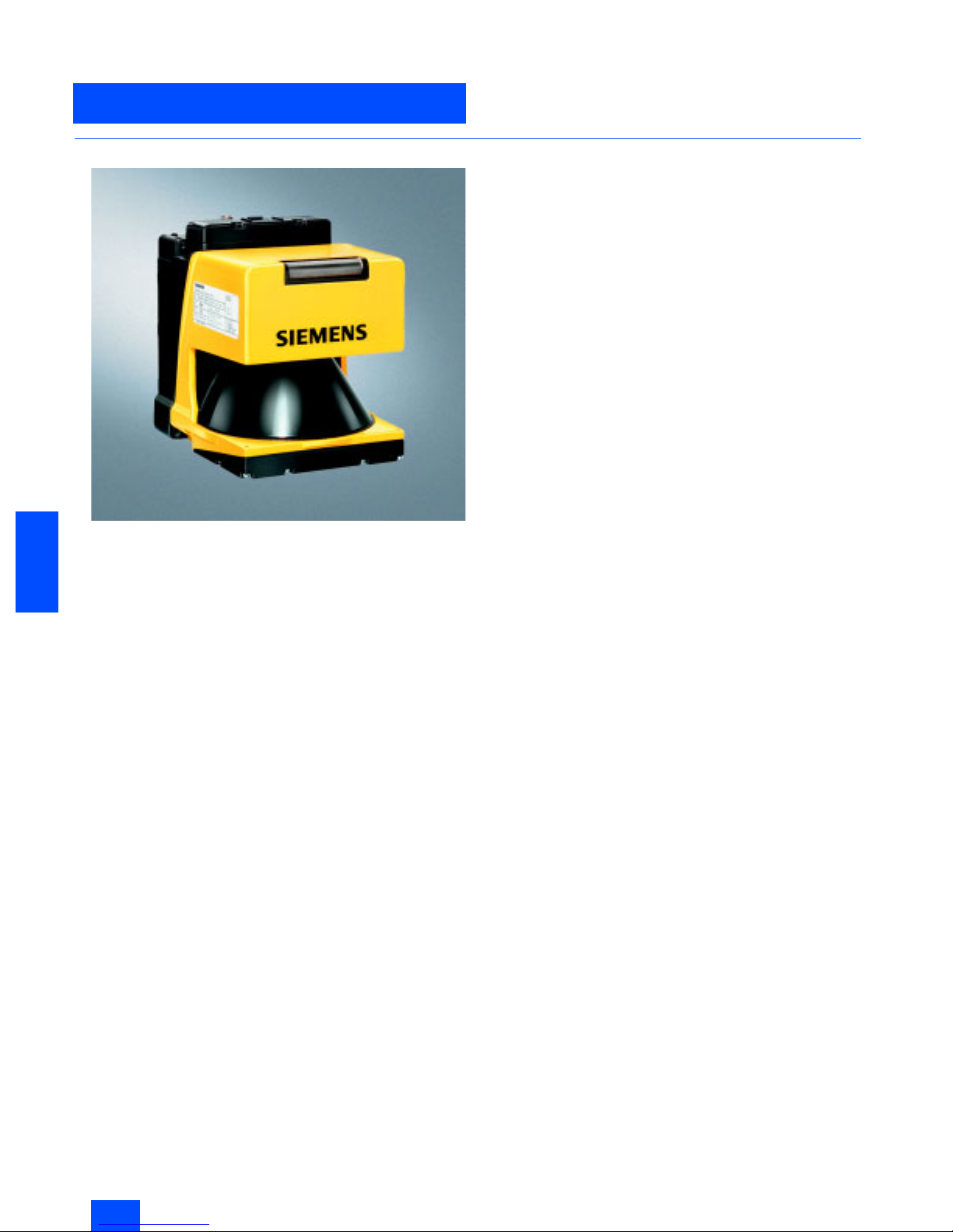
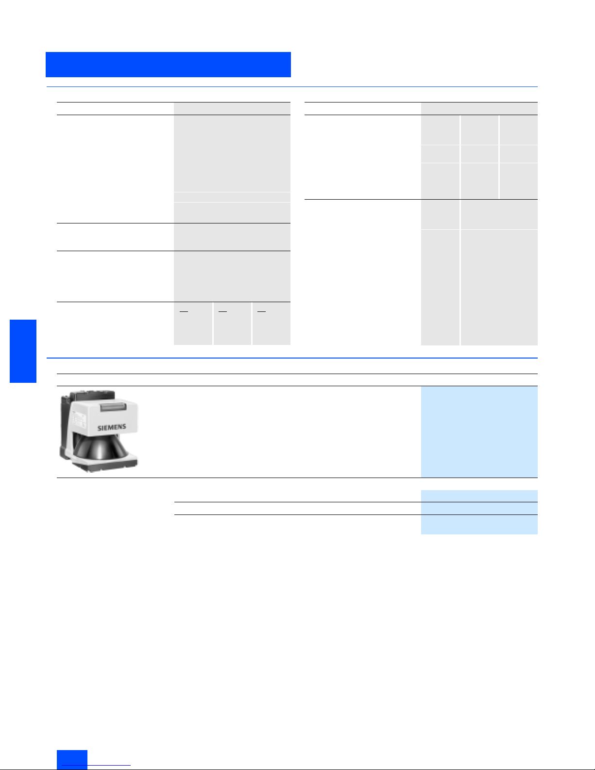
Overview
The LS4 Laser Scanner is an optical distance sensor. The device
periodically transmits light pulses within an operating range of
190°.
If the pulses hit an obstruction or a person, the light is reflected
and then received and evaluated by the LS4 laser scanner. The
scanner calculates the precise coordinates of the obstruction
"seen" from the light propagation time.
If the obstruction or the person is located within defined ranges,
a Stop function is executed. Switch-off is then performed via the
safe interface within the system response time.
The Stop function is reset when the protective zone is free again,
depending on the operating mode, either automatically or following acknowledgement.
Accessories
Accessories include a twistable mounting support, suitable preassembled connecting cables in diverse lengths as well as
spare parts.
Siemens IK PI · 2004
6/25
AS-Interface
AS-Interface Safety at work
AS-Interface laser scanner LS4
6
■
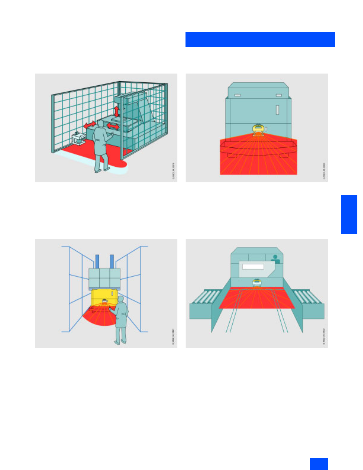
Application
Horizontal danger zone protection
Reliable detection of persons and objects in danger zones of
machines and plants
Flexible configuration of any protection and warning zones to a
great extent
Horizontal danger zone protection with several zones
to be protected
Safe detection of persons in various danger zones by switching
over protection zones
Better availability when specifically securing only live zones
Route monitoring for driverless transport systems
Detection of persons and objects that approach the vehicle
The laser scanner offers a greater protection range than
bumpers and therefore permits higher speeds.
Collision protection for shifting units
Protection of persons who are in the path of the vehicle
Objects in the path of the vehicle are detected early; damage to
the vehicle or load is therefore prevented.
Further applications
• All types of hazardous area protection,
• Room protection and access protection,
• Projecting object monitoring (protection of machines and
persons)
• Non-safety-related measurement or recognition tasks
(e. g. distance, position or contour recognition)
Siemens IK PI · 2004
6/26
AS-Interface
AS-Interface laser scanner LS4
AS-Interface Safety at work
6
■
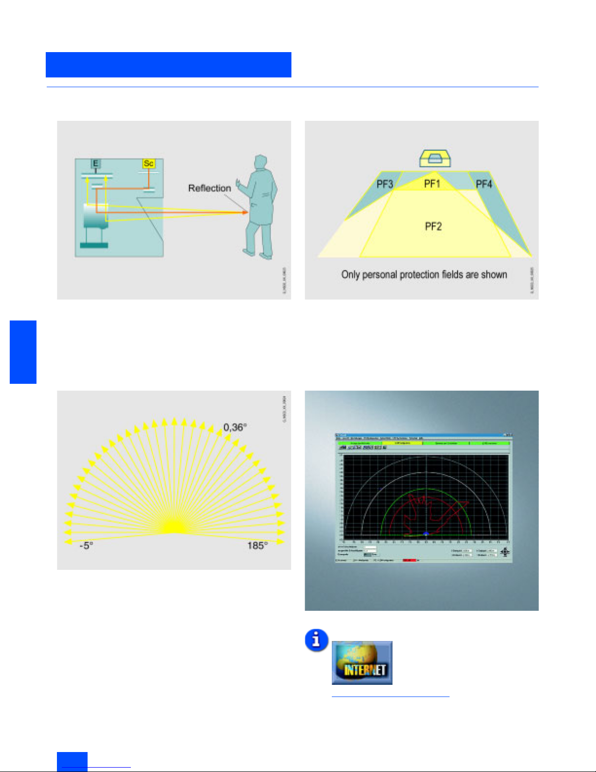
Function
Function principle
Bundled light pulses are created via a laser diode with coupled
transmission optics. These are diverted by a rotating mirror in
such a way that within 40 ms a light pulse is triggered in all angle
segments (scan rate: 25 scans/s). If the light pulse hits an object
or a person, the light is reflected and acquired and evaluated by
the scanner.
Measuring pulse propagation time
The SIGUARD LS4 laser scanner operates by measuring the
pulse propagation time. When extremely short light pulses are
emitted, a time difference occurs between the transmitted and
received light pulse. The propagation time of the light pulse is a
direct measurement of the target distance.
The operating range of the scanner (190°) is subdivided into
angle segments of 0.36°.
Protection and warning field pairs
The device has 4 switchable protection and warning field pairs.
LS4Soft operating software
The SIGUARD LS4 laser scanner must be parameterised using
the associated LS4Soft software. The personal protection and
warning fields required are set in this manner. Also configuration
parameters, such as automatic/manual start, response time and
restart time can be parameterised.
Additional information is available in the Internet under:
http://www.siemens.de/laserscanner

Siemens IK PI · 2004
6/27
AS-Interface
AS-Interface Safety at work
AS-Interface laser scanner LS4
6
■
Technical specifications
LS4-4 AS-Interface laser scanner 3SF7 834-6DD00
Protective zone
• Sensing range in m 0 to 4
• Luminance factor in %
Min. 1.8
• Object size (diameter) in mm
70 (cylindrical test object)
• Response time
- Double evaluation (2 scans)
in ms
85
- Adjustable up to 16 scans in ms
645
•Number
4 (selectable via switch inputs)
• Safety category
Category 3 according to
EN 954-1, Type 3 according to
IEC 61496-1 or EN 61496-3
•Output
Safe AS-Interface connection
•Start-up
Start-up testing and start-up
disable can be set separately
•Restart
160 ms to 10 s
(adjustable or manual)
Protective zone supplement
• For deactivated dust suppression
in mm
81
• For activated dust suppression
in mm
- For protective zone size
< 3.5 mm
81
- For protective zone size
> 3.5 mm
98
• Additional for reflectors in mm
- Over 1.2 m behind the
protective zone line
0
- In the protective zone or up to
1.2 m behind the protective
zone line
110
Warning zone
• Sensing range in m 0 to 15
• Luminance factor in %
Min. 20
• Object size in mm
150 ´ 150
• Response time in ms
- Double evaluation (2 scans) 85
- Adjustable up to 16 scans
645
• Number of warning zones
4 (selectable via switch inputs)
•Output
Connection of AS-Interface
Contour measurement
• Sensing range in m 0 to 50
• Luminance factor in %
Min. 20
•Output
RS 232 serial interface
via infra-red interface
• Radial resolution in mm
5
• Lateral resolution in °
0.36
Supply voltage
• Via AS-Interface network in V 29.5 to 31.6 (according to AS-
Interface specification)
• Via AS-Interface auxiliary voltage
in V
Up to DC 30
• Via external supply in V
24 DC (+/-20 %)
•Note
The power supply unit for the
external supply voltage as well as
the AS-Interface power supply
unit for supplying the AS-Interface components must feature
safe mains isolation according to
IEC 60742 and must bridge temporary mains failures of up to
20 ms (e.g. AS-Interface power
pack 3RX9 307-0AA00)
Overcurrent protection
1.25 A fuse, medium-slow
Supply current in mA
Typ . 3 50
LS4-4 AS-Interface laser scanner 3SF7 834-6DD00
Inputs
• Restart/Reset Connection of a command device
for "with restart lockout“ operating
mode and/or device resets,
dynamically monitored,
24 V DC opto-decoupled
• Zone-pair switchover
Selection of zone pairs via
4 control cables with internal
monitoring (one zone pair =
one protective zone and one
warning zone),
24 V DC opto-decoupled
• Signal definition in V
- High (logical 1) 16 to 30
- Low (logical 0)
< 3
• AS-Interface address
programming
Connection of a generally
available AS-Interface address
programmer
RS232 interfaces for each infrared
interface
For device parameterization and
zone function
Optical system
• Angular zone in ° 190
• Angular resolution in °
0.36
• Lateral tolerance in °
- Without mounting system (with
reference to the rear panel of the
housing)
±
0.18
- With mounting system (with reference to the mounting surface)
±
0.22
• Scan rate
25 scans/s or 40 ms/scan
• Laser protection class
- According to standard EN 60825-1, Class 1
(safe for eyes)
- Wave length in nm
905
- Beam divergence in mrad
2
- Time base in s
100
Degree of protection
IP65
Ambient temperature in °C
•Operation 0 to +50
•Storage
-20 to +60
Housing insulation class
Protection class 2
Humidity
Acc. to DIN 40040, Table 10,
Code Letter E (medium dry)
Dimensions (W x H x D) in mm
140 ´ 168 ´ 165
Control cable X3
• Length in m Max. 50 (for cable cross-section
of 0.5 mm
2
, shielded)
•Note
Shield must be connected to PE
at the cabinet end only
Tran sm it te r
Infrared laser diode (l = 905 nm)
Dimension spacing in mm
• Middle of the scan plane to
bottom edge of housing
48,75
• Rear edge of housing to axis of
rotating mirror
101
Housing
•LS4 Cast aluminum, plastic
• AS-Interface rucksack
Plastic, steel connection plate
Vibration stress over three axes
acc. to IEC 60068, Part 2-6
10 to 150 Hz, max. 5 g
Continuous shock over three axes
acc. to IEC 60068, Part 2-29
10 g, 16 ms
Rotating mirror drive
Brushless DC motor
Rotating mirror bearings
Maintenance-free ball bearings
Siemens IK PI · 2004
6/28
AS-Interface
AS-Interface laser scanner LS4
AS-Interface Safety at work
6
■
Technical specifications (continued)
■
Selection and Ordering data
LS4-4 AS-Interface laser scanner 3SF7 834-6DD00
AS-Interface
• ID code B
• I/O code
0 (four data bits as outputs)
• Slave address
Programmed by the user in the
range 1 to 31 (delivery status = 0)
• Cycle time according to
AS-Interface specification in ms
5
• Profiles
Safe slave
• Electrical connection
-X1 M 12 plug, AS-Interface
-X2
M 12 plug, 24 V external
Assignment of data bits D0 ... D3
Protective zone empty:
Code sequence
Protective zone occupied: 0
Assignment of the diagnostic
parameter bits
P0 = Alarm (according to LS4
programming)
P1/2 = SF coding
(see assignment of SF coding)
P3 = LS4-RESET (via PC/ASInterface master call)
Assignment of SF coding
P2
0
0
1
1
P1
0
1
0
1
SF
1
2
3
4
LS4-4 AS-Interface laser scanner 3SF7 834-6DD00
Assignment
PIN1 PIN2 PIN3
• X1 (M12 plug for device
connection)
AS-i+ -- AS-i-
• X2 (M12 connector for external
power supply)
24 V DC
supply
24 V Out Mass
• X3 (M12 socket for protective
zone changeover)
SF pair 1 SF pair 2 SF pair 3
• X4 (AS-Interface addressing
socket)
AS-i+ AS-i- --
Assignment
PIN 4 PIN 5
• X1 (M12 plug for device
connection)
– –
• X2 (M12 connector for external
power supply)
Start/
Reset
PE
• X3 (M12 socket for protective
zone changeover)
SF pair 4 24 V Out
• X4 (AS-Interface addressing
socket)
– –
Design
Order No.
AS-Interface LS4-4 laser scanner
Including LS4soft Software
3SF7 834-6DD00
Accessories
Mounting system
3RG7 838-1AA
Adapter plate
3RG7 838-1AB
PC cable connector
Including plug, 9-pole and optical interface
3RG7 838-1DC
Siemens IK PI · 2004
6/29
AS-Interface
AS-Interface Safety at work
AS-Interface laser scanner LS4
6
■
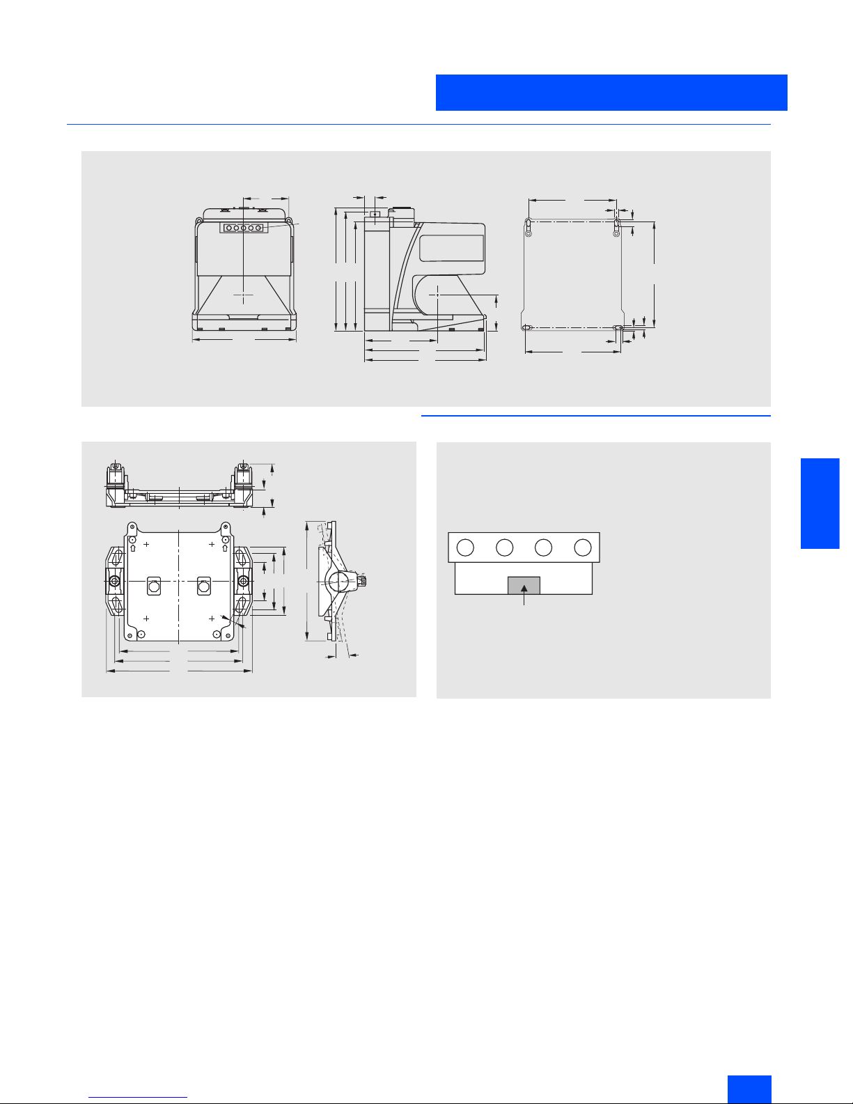
Dimensional drawings
LS4 laser scanner
Assembly system
■
Schematics
N S C 0 _ 0 0 6 3 0
1 4 9
1 6 3
1 6 8
1 0 1
1 6 5
1 6 8
4 9
1 3 , 5
6 1
L E D
( 5 x )
1 4 0
5 , 2
1 4 4
5
9 , 5
1 2 9
5 , 2
1 2 2
9 , 5
23
56,6
51,5
74,4
90
158
166
192
155,4
9°
NSC 00610
9
X 2
N S C 0 _ 0 0 6 3 1 a
X 3 X 4 X 1
O p t i c a l i n t e r f a c e
M 1 2 c o n n e c t o r , A S - I n t e r f a c e
M 1 2 c o n n e c t o r ,
o p t io n a l a u x i l i a r y v o l t a g e
M 1 2 s o c k e t , p r o t e c t i o n f i e l d
c h a n g e - o v e r
A d d r e s s i n g s o c k e t ,
A S - I n t e r f a c e
X 1 :
X 2 :
X 3 :
X 4 :
Siemens IK PI · 2004
6/30
AS-Interface
AS-Interface EMERGENCY STOP pushbuttons
AS-Interface Safety at work
6
■
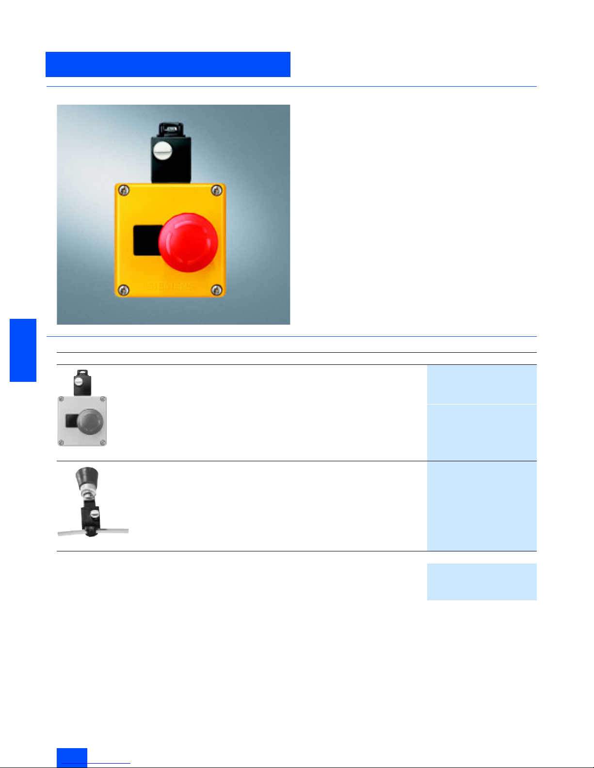
Overview
It is also possible now to connect EMERGENCY STOP devices
via the standard AS-Interface with safety-oriented communication. This only applies to EMERGENCY STOP devices of the
SIGNUM 3SB3 command devices for front panel installation and
for installation in an enclosure.
■
Selection and Ordering data
1) See Catalog LV 10, Section Pushbuttons and Indicator Lamps
Design
Order No.
3SF5 801-3AA08
AS-Interface EMERGENCY STOP housing
Two NC contacts
AS-Interface F adaptor
• Yellow cover
3SF5 801-3AA08
• Yellow cover with protective collar
3SF5 801-3AB08
3SF5 402-1AA01
AS-Interface EMERGENCY STOP front plate /
AS-Interface F adaptor
For AS-Interface EMERGENCY STOP
Front panel mounting
EMERGENCY STOP actuator is not included
1)
3SF5 402-1AA01
Accessories
Safety Integrated manual
•German
E20001-A110-M103
• English
E20001-A110-M103-X-7600
 Loading...