

Siemens IS404, IS404H Instruction Manual
Installation manual 008167_c_−−_−−
Edition 04.2007
Supersedes 008167_b
1
IS404 / IS404H
Outdoor PIR detector
Aussenbereichs PIR Melder
Détecteur IRP extérieur
Rivelatore PIR per l’esterno
Detector PIR de exterior
PIR detector voor buiten
2
IS404
Mounting height
Montagehöhe
Hauteur de montage
Altezza di montaggio
Altura de montaje
Montagehoogte
4.0m
Ø 40...160mm
Screws
Schrauben
Vis
Vite
Tornillos
Schroefjes
5 x 60mm
Fire & Security Products
Siemens Building Technologies
IS404H
120
1 m
2 m
3 m
m
4 m
0 16 45
LM
S
8
120m
2.7m
150
1 m
2 m
3 m
m
4 m
0 16 45
LM
S
8
150m
3.3m
1.5m
1.5m
Mounting height
Montagehöhe
Hauteur de montage
Altezza di montaggio
Altura de montaje
Montagehoogte
4.0m
1,5m
Monitored area
Überwachter Bereich
Zone controlée
Area sorvegliata
Area vigilada
Bewaken gebied
120m (IS404)
150m (IS404H)
3
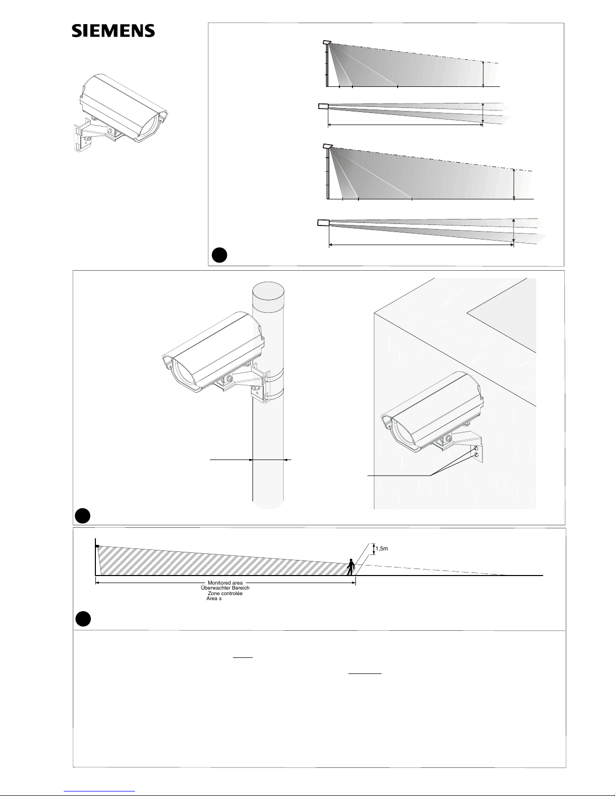
Fig. 3 Typical vertical alignment of detectors for a required detection range (details see fig. 1)
The detector should be aligned vertically so that at least the lower half of a person standing upright at the maximum required range will be within the field of view
Typische vertikale Ausrichtung von Meldern für einen benötigten Detektierbreich (Details siehe Fig. 1)
Der Melder muss so ausgerichtet werden, dass am Ende des zu überwachenden Bereichs mindestens
die untere Hälfte einer aufrecht stehenden Person erfasst wird.
Alignement vertical des détecteurs pour une zone de détection requise (voir fig. 1)
Le détecteur doit être aligné de façon que les jambes d’une personne situé à l’extrémité de la zone sensible de détection déclenchent une alarme.
Allineamento verticale tipico per l’area di copertura definita (per dettagli vedere fig. 1)
Il rivelatore deve essere orientato in modo tale che all’estremità del campo sotto controllo venga rivelata almeno la metà inferiore di una persona ritta in piedi.
Alineación vertical típica para el rango de detección requerido (ver detalles en fig. 1)
El detector se debe alinear de tal modo que al menos se detecte la mitad inferior de una persona de pié al final del área controlada.
Typische vertikale uitlijning van de gewenste detectieafstand (details zie figuur 1)
De detector moet zo worden gericht dat aan het einde van het te bewaken bereik ten minste de onderste helft van een rechtop staande persoon wordt geregistreerd.
ISMD41−3
Pole Mount Hardware
Hardware für Masthalterung
Matériel monté sur poteau
Ferramenta per montaggio a pilastro
Hardware para montaje en poste
Materiaal voor paalmontage
008167_c_−−_−− p2
4
Alignment of detector
Vertical alignment is optimal when the upper edge of the field of view is at 1.5 to 2.5 m
above ground at the end of the required detection range provided that the field of view is
properly terminated. Refer to fig. 3.
Coarse alignment can be done visually by looking along the groove on top of the detector.
Please note that the groove on the detector cover points the top margin of the effective
range.
Fine alignment can easily be achievied with telescope ISTC41 (order no
BPZ:4455260001) and monitored walk tests.
Ausrichten des Melders
Die vertikale Ausrichtung ist optimal, wenn der obere Rand des Sehbereiches bei 1.5 bis
2.5 m über Boden am Ende der Strecke des benötigten (vorgesehenen) Wirkbereiches
liegt. Siehe Figur 3.
Eine grobe Ausrichtung kann visuell entlang der Rille auf dem Melderdeckel erfolgen.
Bitte beachten Sie, dass die Rille auf dem Melderdeckel den oberen Rand des Wirkbereichs zeigt.
Die genaue Ausrichtung kann sehr einfach mit dem Fernrohr ISTC41 (Bestell−Nr.
BPZ:4455260001) sowie durch Gehtests erfolgen.
Alignement du détecteur
L’alignement vertical est optimal lorsque le bord supérieur du champ visuel est entre 1.5
et 2.5 m au−dessus du sol à l’extrémité de la portée souhaitée de détection, à condition
que le champ visuel se termine correctement (présence d’un arrière plan). Voir fig. 3.
L’alignement général peut être fait visuellement en regardant le long de la rainure sur le
détecteur. Veuillez noter que la rainure sur le boîtier du détecteur correspond à la limite
supérieure de la portée utile.
L’alignement précis peut facilement être réalisé avec le télescope ISTC41
(BPZ :4455260001) et en réalisant des tests de déplacement.
Orientamento del rivelatore
L’allineamento verticale può considerarsi ottimale quando il limite superiore più distante
del volume sorvegliato è posizionato tra 1,5m e 2m sopra il punto di terra posto al margine dell’area di copertura richiesta, premesso che il campo visivo sia determinato, ovvero non si perda all’infinito.
L’allineamento di massima può essere eseguito visivamente traguardando tramite la
scanalatura posta nella parte superiore del rivelatore. La linea di mira corrisponde alla
delimitazione superiore del volume sorvegliato.
L’allineamento fine può essere eseguito in modo molto semplice tramite il telescopio
IST41 (codice d’ordinazione BPZ:4455260001) e commutando il rivelatore in test di attraversamento (walk test).
Alineación del detector
La alineación vertical es óptima cuando la altura sensible de detección se encuentra entre 1,5 y 2,5 m, medidos en el extremo de detección y el alcance está limitado por una
barrera, tal y como se ha comentado en el parrafo anterior (ver la fig. 3).
La alineación vertical inicial puede ser ópticamente efectuada mediante la estría situada
en la parte superior, aunque esto es válido para la alineación horizontal (altura de detección).
Esta alineación más precisa se obtiene mediante el accesorio ISTC41 (Cod.
BPZ:4455260001), efectuando a continuación test reales de desplazamiento.
Detector richten
De vertikale uitlijning is optimaal als de bovenste hoek van het zichtveld, aan het einde
van de detectiebereik, zich zo’n 1,5 tot 2,5 meter boven de grond bevindt, ervan uitgaande dat het zichtveld goed is bepaald. Zie figuur 3.
Grofweg uitlijnen kan op het oog gedaan worden door in lijn met de groef bovenop de
detector te kijken.
Fijnamstemming kan eenvoudig worden gedaan met de telescoop ISTC41 (bestelnummer BPZ:4455260001) door middel van gecontroleerde looptest.
8
7
6
5
4
3
2
1
B
A
100mA
50mA
+6V
Relay shown in energised (non-alarm) condition
Relais in aufgezogenem Zustand (kein Alarm) gezeichnet
Le relais est dessiné à l’état activé (pas d’alarme)
Il relè è disegnato in stato eccitato (nessun allarme)
El relé ha sido dibujado en estado excitado (sin alarma)
Relais in aangetrokken toestand (geen alarm) getekend
*
ON
1 2 3 4 5 6
Tamper
Test
(RJ12)
5
Alimentation
AlimentazioneSpeisung
Supply Alimentación
Voeding
Sortie el. d’alarme
Uscita el. d’allarmeEl. Alarmausgang
El. alarm output
El. alarmuitgang
Salida el. de alarma
Relais d’alarme
Relè d’allarmeAlarmrelais
Alarm relay Relé de alarma
Alarm relais
vide
riservaleer
spare reserva
reserve
RS485
Contact d’autoprotection
Contatto del coperchio
Sabotagekontakt
Tamper contact
Contacto de la tapa
Sabotagecontact
*
+10.5V...30VDC / 24VAC
*
008167_c_−−_−− p3
Application guidelines
IS404: Curtain detection, range 120m.
IS404H: Curtain detection,with heating,
range 150m.
Installation
Coverage zone (Fig. 1)
The detector reacts to fast and slow movements
of an intruder within the specified environmental
conditions. The detection capacity is, however,
reduced where there is only a slight temperature
difference between the intruder and environment or where weather conditions are extreme.
The reaction of the detector is most sensitive to
movements which are transverse to the coverage zone.
The coverage zone is limited by walls and
other objects.
The following points shall be noted to obtain
optimum sensitivity and reduce false alarms.
−Align the coverage zone so that it is bounded
at the end by a reference which is as uniform
as possible (floor, wall).
−Align the detector so that a potential intruder
has to pass through the complete coverage
zone.
−There should be no large objects within the
coverage zone, which, for instance, could
move considerably due to wind gusts (large
branches, bushes, high grass).
−The inadvertent intrusion of people and animals must be prevented, e.g. by a fence.
For installations where the range of a detector
is not sufficient, subdivide the area to be monitored into sections covered by several detectors.
Note that the masking of the coverage zone
is not monitored.
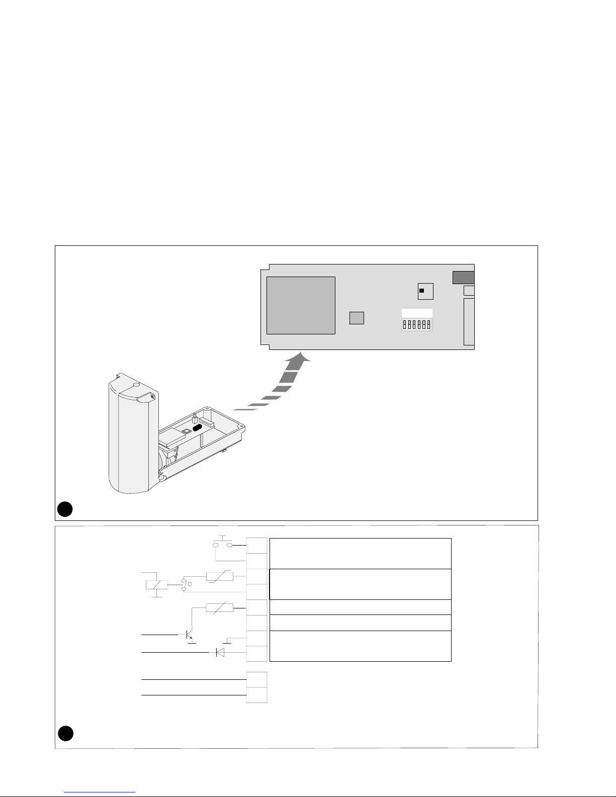
Mounting (Fig.2)
The detector is to be mounted 2.5m to 4.0m
above the ground
−either by screwing to a stable surface
or
−strapping to a stable pole.
The cable inlets must not be changed.
Do not seal the cable inlets because otherwise condensation can form within the detector.
If the cable diameter is too small, reinforce
the cable using insulating tape.
Alignment of detector
The detection range of a PIR detector is not limited but a function of size, speed and temperature
contrast of a target against its background. The
detector should be aligned so that a natural or artificial background at the end of the range terminates the field of view.
For details refer to fig. 3
The monitored area must then be checked
by a walk test. Refer to ”Walk test” section.
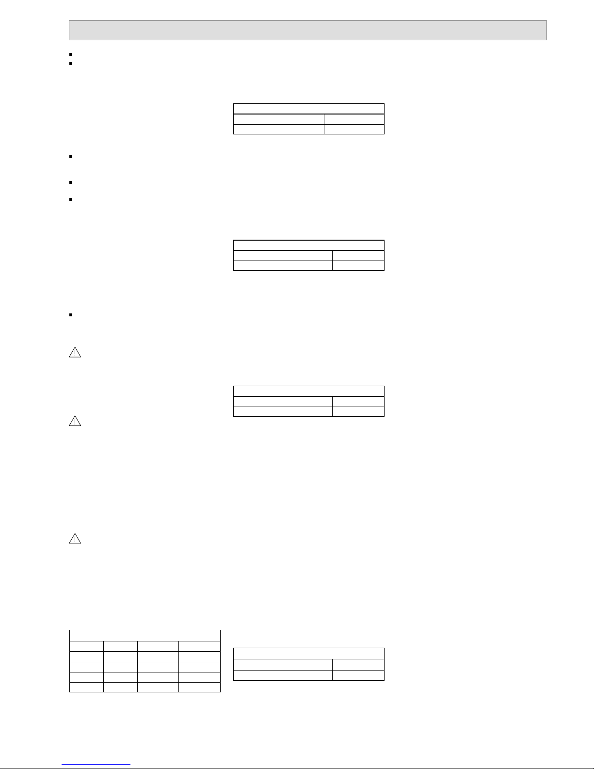
Wiring (Fig. 5)
The diagram shows the terminal block connections.
Programming
Sensitivity
The various settings of the IS404 are made by
means of multiple DIP−Switches on the printed
circuit board.
DIP1−DIP2 Sensitivity
IS404 IS404H DIP 1 DIP 2
60m 75m OFF OFF
84m 105m OFF ON
Max. Max. ON OFF
Software Software ON ON
The DIP–Switches 1 and 2 are for sensitivity
setting depending on the required detection
range. If the maximum required range is less
than the nominal range of the detector, it is recommended to reduce the range setting to reduce nuisance alarms.
Mounting height
The IS404 is designed for mounting at heights
between 2.5 and 4.0 m above ground. The DIP −
Switch 4 is used to set the relative sensitivity of
all detection zones in function of the mounting
height as recommended below:
DIP4 Mounting Height
Low <3.0m OFF
High >3.0m ON
If the mounting height is less than 2.5 m, a detection gap at app. 10 m distance may be observed
for fast movements. This is due to the overlap of
the three zones and resulting rejection of simultaneous signals.
Adaptive threshold decoding (ATD)
The background noise is constantly averaged
and used to adjust the threshold levels for the
alarm. This special feature is reducing the probability of nuisance alarms caused by wind, moving vegetation or objects that have a thermal
contrast although usually weaker than a person.
DIP3 Adaptive Threshold Decoding
ATD OFF OFF
ATD ON ON
Internal Heater (IS404H only)
A regulated heater connected to the electronic
board and powered by the supply voltage of the
IS404H prevents the optical surfaces from fogging or frosting and maintains the internal temperature at optimal levels.
Walk test
Doing walk test using the ISWT41, in HW mode
the DIP−Switch 5 needs to be set to ’on’. After
the walk test, the ’test’ mode needs to be
switched ’off’.
DIP5 Walk Test
Test OFF OFF
Test ON ON
Important: The transmitter ISWT41−T of the
cordless installation tester has to be placed
within the housing with the detector cover closed
and securely tightened. The antenna of the
transmitter needs to be placed straight in the detector housing.
Anti Vandal Function
The IS404/IS404H is equipped with a sophisticated protection against vandalism. These detectors can sense certain changes of their alignment from the original position as set during the
installation. A change of the detectors alignment
generates a permanent alarm until the detectors
alignment is back in its original position or until
the position has purposely been reset.
After the turn−on time of typ. 60 seconds from
power on, the detector determines and stores its
alignment position (only with detector cover
closed).
After opening and closing the cover with the unit
powered on, the detector determines its alignment position and stores the position value after
5 minutes again without having the detector in
permanent alarm state.
The anti vandal sensor can be reset with a power
off−on (60 seconds).
DIP6 Anti Vandal Function
Anti Vandal OFF OFF
Anti Vandal ON ON
Hardware Mode:
When operating the detector in the HW mode,
the anti vandal function is activated by setting
’DIP’ switch 6 to ’ON’
Maintenance
Check the detector regularly (at least twice a
year) for correct functioning (walk test), cleanliness and security of attachment.
−Clean the detector window only with a soft
cloth. Do not use solvents.
−Check the inside of the detector for humidity
and correct sealing of the cover.
−After extreme weather conditions (storm,
snowstorm, hail etc.), check the detector for
damage. Remove snow or dust from the detector window.
Accessories
Interface Module ISIF485B and Installation Software
The Installation Software is very useful for alignment and signal check during setting up and routine maintenance. It will indicate the amplitudes
generated by wanted as well as unwanted targets and help setting the gain control correctly
during walk tests and also show the magnitude
of disturbance signals. The installation software
is to be installed on a PC; an interface module is
required to convert RS232/USB to RS485. The
information for installation and signal monitoring
is displayed on the screen of the PC.
If more than one detector is connected to the
same RS485 communication bus, each detector
needs to have a different address (ID)
The RS485 standard requires a bus topology. To
ensure proper communication, the data must be
terminated on both ends. The ISIF485B features
a built−in termination resistor.
The input cable is 5.0m long and is terminated
with a RJ12 connector fitting into the test socket
on the electronic board of the detector.
Technical data
Supply
Supply voltage 10,5...30,0VDC/24VAC
. . . . . . . . . . . . . . .
Power consumption (at 12VDC):
− quiescent current IS404 / IS404H 18mA
. . . . . . . . . . .
Heating power: typ. 2W at −40°C. . . . . . . . . . . . . . . . . . . .
Alarm outputs
Relay open on alarm
. . . . . . . . . . . . . . . . . . . . . . . . . . . . . . . . .
− alarm holding time >2.5s. . . . . . . . . . . . . . . . . . . . . . . . . . .
− contact load 30VDC/100mA. . . . . . . . . . . . . . . . . . . . . . . .
Electronic output, terminal 4 alarm ⇒ 0V. . . . . . . . . . . .
open collector
Tamper contact
− contact load 30VDC/100mA
. . . . . . . . . . . . . . . . . . . . . . . .
Environmental conditions
− operating temperature
IS404 −20°C...+60°C
. . . . . . . . . . . . . . . . . . . . . . . . . . . . . . .
IS404H −40°C...+60°C. . . . . . . . . . . . . . . . . . . . . . . . . . . . .
− air humidity EN60721 <95%rF, not condensing. . . . .
− housing protection
class EN60529, EN50102 IP64
. . . . . . . . . . . . . . . . . . . . . .
Order information
IS404 PIR detector, curtain A5Q00005097. . . . . . . . . . .
IS404H PIR detector, curtain,
with Heater A5Q00005096
. . . . . . . . . . . . . . . . . . . . . . . . . . .
ISIF485B Installation module
and SW A5Q00026219
. . . . . . . . . . . . . . . . . . . . . . . . . . . . . . .
ISMD41−3 Pole Mount Hardware A5Q00026220. . . . .
ISWT41 Cordless Walktester A5Q00026218. . . . . . . . .
 Loading...