

Siemens IR270CT User Manual
007038_b_- -_-- p1
Installation manual 007038_b_--_-Edition 07.2003
Supersedes 007038_a_--_-PN A5Q00003280
IR270CT
Passive infrared detector with antimask
Passiv-Infrarotmelder mit «Antimask»
Détecteur infrarouge passif avec «antimask»
Rivelatore passivo a infrarosso con «antimask»
Detector a infrarrojos pasivos con «antimask»
Passief-infraroddetector met «antimask»
Made in Switzerland
3
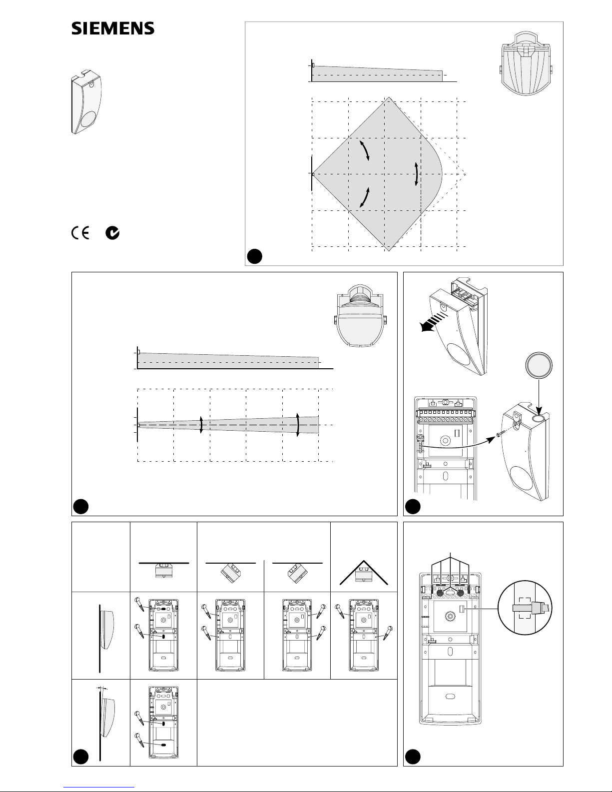
Wide angle mirror
Weitwinkel-Spiegel
Specchio grandangolare
Espejo gran angular
BreedhoekspiegelMiroir grand-angle
IRS272 PN 571 733
Miroir rideau
Specchio a tendaCurtain mirror
Vorhang-Spiegel Espejo de cortina
Gordijnspiegel
4
1
BreedhoekspiegelMiroir grand-angle
15m10m5m0
h = 2,2m 7.2ft
max. 2,5m 8.2ft
min. 2,0m 6.5ft
0
0
0,9m
20m
2
15m10m5m0
5m
0
20m
1m
h = 2,2m 7.2ft
max. 3,5m 11.5ft
min. 2,0m 6.5ft
0
0,9m
25m
Wall mounting
Wandmontage
Montage sur mur
Montaggio a muro
Montaje en pared
Montage op een mur
Corner mounting
Eckmontage
Montage dans un angle
Montaggio ad angolo
Montaje en esquina
Montage in een hoek
45° mounting
45°-Montage
Montage 45°
Montaggio 45°
Montaje 45°
Montage 45°
2°
A
B
5
B
A
Fire & Security Products
Siemens Building Technologies
16ft 32ft 50ft 65ft
3ft
3ft
16ft 32ft 50ft 65ft 80ft
16ft
3.3ft
1m 3.3ft
5m 16ft
5m 16ft
5m 16ft
10m 32ft
10m 32ft
007038_b_- -_-- p2
86
Störungs- & Antimask-Relais
Relay shown in energised (non-alarm) condition
Relais in aufgezogenem Zustand (kein Alarm) gezeichnet
Le relais est dessiné à l’état activé (pas d’alarme)
Il relè è disegnato in stato eccitato (nessun allarme)
El relé ha sido dibujado en estado excitado (sin alarma)
Relais in aangetrokken toestand (geen alarm) getekend
*
2
1
11
10
8
7
+
-
Relais dérangem. & masquage
Relè guasto & mascheramento
*
Dist. & Antimask relay
Rele de avería y antienmascaramiento
Storing & antimask relais
Contact d’autoprotection
Contatto del coperchio
Sabotagekontakt
Tamper contact
Contacto de anti-arranque
Sabotagecontact
Alimentation
Alimentazione
Speisung
Supply
Alimentación
Voeding
4
Test de déplacement
Test di attraversamento
Gehtest
Walktest
Looptest
Ensayo de desplazam.
5
non amorcé
disarmato
+5V
Unscharf
Unset
onscherp
desarmado
13
12
vide
riserva
leer
spare
reserva
reserve
<45R
30V
8...16V
+5V
7
*
<45R
30V
15
14
Relais d’alarme
Relè d’allarme
Alarmrelais
Alarm relay
Rele de alarma
Alarm relais
10
Avoid direct or reflected sunlight.
Direkte oder reflektierte Sonnenstrahlung vermeiden.
Eviter le rayonnement solaire direct ou indirect.
Evitare luce solare direttamente o indirettamente.
Evite las incidencias directas o indirectas de los rayos solares.
Vermijd direct of indirect zonlicht.
Do not install the detector outdoors.
Melder nicht im Freien montieren.
Ne pas monter le détecteur à l’extérieur.
Non montare il rivelatore all’aperto.
No montar el detector al aire libre.
Uitsluitend voor installatie binnenshuis.
Avoid looking directly at air conditioning or heat sources.
Zonen nicht direkt auf Kälte- bzw. Wärmequellen richten.
Ne pas diriger les zones sur radiateurs ou climatiseurs.
Non indirizze le zone su radiatori o condizionari d’aria.
No dirigir las zonas encima de calefactores o aparatos de aire
acondicionado.
Richt de zones nooit op verwarmde oppervlakten of
airconditioners.
Detector breakage/removal monitoring
Abreißüberwachung
Contrôle d’arrachement
Controllo dello strappo
Control de ruptura
Afbreekbeveiliging
Back tamper contact
Abreißkontakt
Contact d’arrachement
Contatto di strappo
Contacto anti-arranque
Afbreekcontact
4
9
Changing the mirror
Spiegel wechseln
Remplacement du miroir
Sostituzione dello specchio
Cambio del espejo
Spiegel vervangen
IRUM20, IRUM30 Mounting brackets
Montagehalter IRUM20, IRUM30
Supports de montage IRUM20, IRUM30
Supporti IRUM20, IRUM30
Soportes de montaje IRUM20, IRUM30
Montagehouders IRUM20, IRUM30
TOP
Cable knock-out
Kabeldurchführung
Passage de câble
Foro per il cavo
Orificio para cable
Kabelpassage
Cable attachment
Kabel-Befestigung
Fixation du câble
Fissaggio per cavo
Fijación del cable
Kabelbevestiging
IRUM20
IRUM30
PN 562 247
PN 562 250
007038_b_- -_-- p3
IR270CT Instruction for use
H The detector reacts most sensitively to movement which proceed at right
angles to the coverage zones (the direction of the arrow in figures 1 and 2).
H The detector’s coverage area is limited by any solid objects.
H The detector is designed to achieve optimal response sensitivity and a high
level of false alarm suppression. Nevertheless, you are recommended to
take note of the following points (see also figure 10):
- Do not direct the zones at sources of heat or cold, nor at points subject to
strong sunlight.
- Direct the zones towards uniform references. Zones which are directed
towards heaters (including floor heating equipment) can reduce the probability of detection of movement.
- If it is impossible to avoid positioning the detector above heaters, you
must keep them at a minimum distance of 1.50m / 5ft away!
H The integrated breakage/removal contact and the «real time» antimask sur-
veillance system mean that security against tampering satisfies the highest
requirements. What is more, all the functions of the entire detector (including the detection sensors) are constantly monitored.
Anti-masking and alarm memory features are not verified by UL.
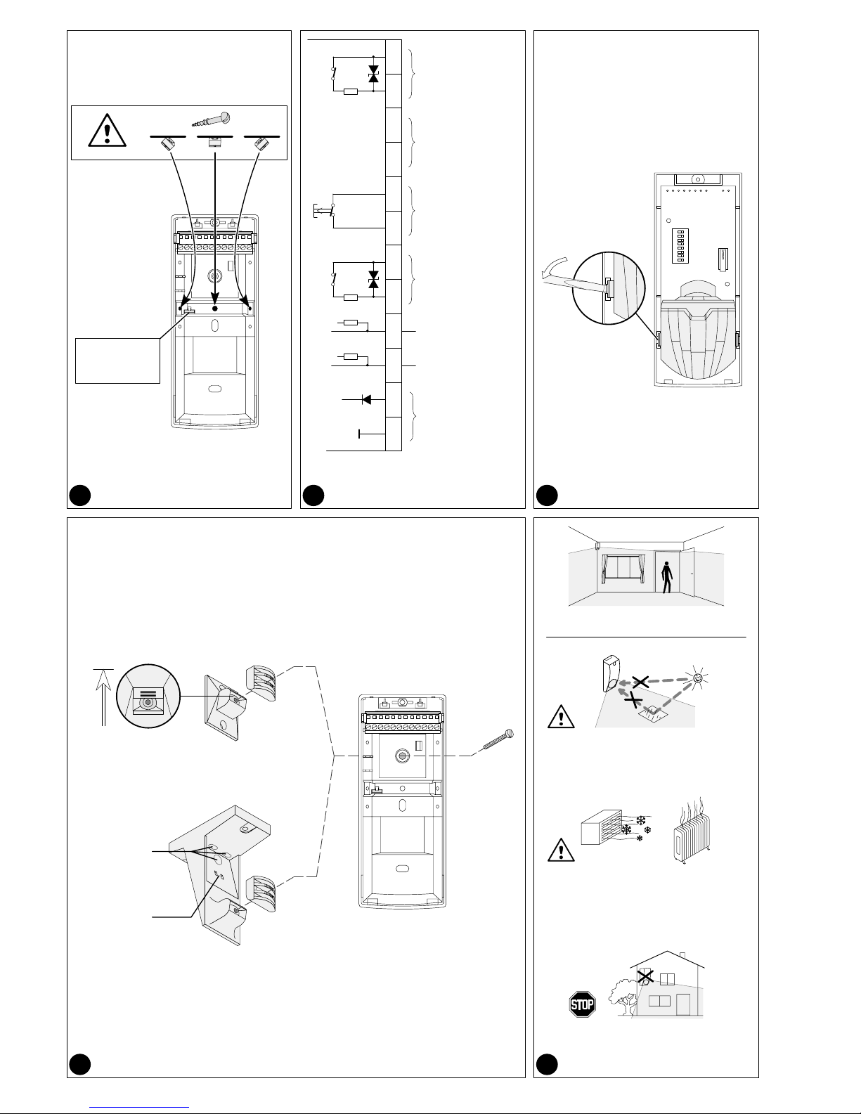
Installation
The detector is intended for use in inside rooms.
Do not remove the printed circuit board from the detector. There is a dan-
ger that it may be damaged!
1. Open the detector (figure 3).
2. Mount the detector on a stable vertical surface.
- Select the height (h) above the floor according to figure 1 or 2.
- Corner mounting and 45° installation (right / left) are possible without any
accessories (see figure 4A).
- Detector must be inclined at an angle of 2° when mounting above 3m / 10ft
in order to detect crawling intruders and to ensure the detection range (see
figure 4B).
- The cable is introduced through one of the knock-out points A (see figure 5).
3. Wire the connections as shown in figure 7.
4. For strain relief on the connection cable, pierce the lug B (figure 5) and fix
the cable with a cable cleat.
5. Select the desired settings as shown in the section on ”Programming”.
6. Replace the cover, screw it down with the screw provided, and close the
screw cover (figure 3).
Detector breakage/removal monitoring Figure 6
If the detector is forcibly removed from the mounting surface, a sabotage
alarm is triggered.
For this, the detector base must be secured with an additional screw.
This feature is not verified by UL.
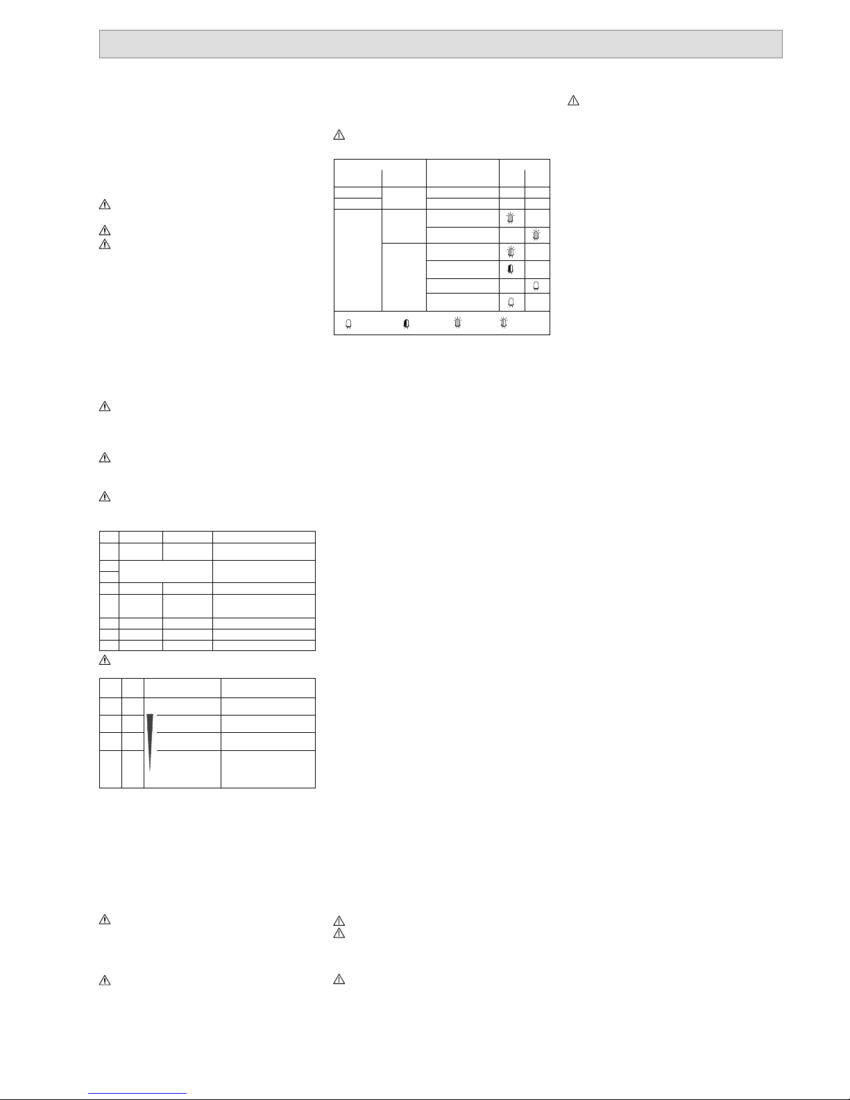
Control inputs Figure 7
Walktest remote control Terminal 4
Remote control of the walktest indicator. Use switch DIP1 to select the polarity
of the control signal.
Walk test remote control is not verified by UL.
Set/unset remote control Terminal 5
Remote control of the set/unset state. Use switch DIP4 to select the polarity of
the control signal.
An open control input is HIGH (internal pull-up); for control with active
HIGH, a resistor (t y p . 2 k Ω, max. 47kΩ/detector) must be switched to 0V.
Programming
You can use switches DIP1 to DIP8 to select the following functions:
DIP ON OFF (default) Function
1 LOW (0V) HIGH (+12V)
Potential for walktest ON at terminal 4
2
3
see ”Detection sensitivity” tableSensitivity of motion detection
4 LOW (0V) HIGH (+12V) Potential for unset at terminal 5
5
To disturbance and
alarm relay
To disturbance
relay only
Detector function monitoring, disturbance (DIST) and antimask
(AM)
6 High Standard Antimask sensitivity (AM)
7 Latch Real time Antimask function (AM)
8 - - -
For installations with intrusion detection control units without disturbance input, set DIP5 to ON.
Detection sensitivity
DIP2 DIP3 Sensitivity /
Range
Application
ON ON
High values
18m 60ft
Stricter detection requirements
OFF OFF
Standard (default)
18m 60ft
Residential, offices
ON OFF
Increased stability
18m 60ft
Rooms with low sources of interference
OFF ON
Harsh environment
12m 40ft
Not approved for
ANPI, CNMIS, IMQ,
UL, SKAFOR
Rooms with considerable interference effects
Setting note
If the longest wall in the room is less than 5m / 16ft, do not use the «High values» sensitivity setting!
Functions
Detector function monitoring (self-test) DIP5
A self-test is always carried out when the supply voltage is applied. The detector is also equipped with a periodic self-test.
A malfunction (such as a sensor failure) is indicated as a disturbance by the
continuously red LED, and also at the disturbance output (terminals 7+8); and
if DIP5 = ON, it is also outputted to the alarm relay in the unset mode.
Antimask surveillance
When masking is performed which restrict the motion detection, an antimask
signal is outputted via output DIST. & AM (terminals 7+8), and during walktest,
the masking indicator (LED lights green) is activated.
To ensure reliability of operation, detector covers must be replaced if they
have been sprayed. Cleaning them is not enough.
Sensitivity of antimasking surveillance DIP6
- Standard
Recommended setting to detect masking.
- High
This setting enables faster and more sensitive masking detection for very
high risks.
Depending on the masking material, the range of the antimask surveillance is approximately 0.20m / 0.7ft.
Antimask surveillance function DIP7
- Real time
The antimask signal follows the state of the detector. Masking will only be
indicated as long as the detector is masked. This is the setting recommended by the manufacturer.
- Latch
Once the antimask signal is activated, it is retained (stored) on self-hold until
it is reset by carrying out an antimask surveillance reset.
Antimask surveillance reset
- Variant1
With masking present, switch over to walktest ON:
- Remove the masking and trigger the motion alarm;
- Switch back to unset, and the antimask surveillance will then be re-initial-
ised.
- Variant 2
Restart due to voltage cut.
The detection area must be checked after every reset or restart.
LED displays
Control line state Detector state LED
Arming,
terminal 5
Walktest,
terminal 4
red green
Change to set
Memory reset - -
Set
any
Memory set - Alarm stored -
Walktest OFF
Masking stored (AM) -
Self-test at start-up
-
Unset
Walktest alarm -
Walktest ON
Masking -
Disturbance (DIST)
-
lit
flashing
constantly
lit
for 2.5s
slow
flashing
Memory displays
Set memories are shown in the unset with walktest OFF state.
The alarm memory (LED flashes red) shows the result of the last set period.
This memory is always reset when the system is next in the set state.
The masking memory (LED flashes green) is set when an event of the rele-
vant type has been continuously or temporarily present during the previous
set period. This memory is reset when the system is next in the set state, provided that the masking is no longer present.
Commissioning
1. Switch on the supply voltage.
During the self-test and the start-up phase with walktest ON, the LED flashes
red slowly for about 1 minute.
- When the LED goes out, the detector is ready.
- If the LED lights red continuously, there is a fault in the detector.
2. Carry out the walk test, i.e. check the complete monitoring area to make
sure the alarm triggers:
Walk upright across the active area at a rate of about 1 step per second in the
direction shown by the arrows (fig. 1 or 2) and pause. An alarm should be triggered in approx. 2 to 3 seconds!
The detector must also trigger an alarm if the active area is crossed near to its
edges.
Sealing the detector Figure 3
If sealing of the detector is prescribed, apply an adhesive seal over the gap
between the base of the detector and the cover.
Maintenance
Check the function of the detector regularly (at least once per year) - carry out
a walktest, check for dirt and inspect the fixture.
Troubleshooting
Detector does not react
- Check whether the mirror is inserted.
- Check the supply voltage and polarity.
No alarm display on the detector
- Check programming, control signals and polarities.
No alarm
- Check the alarm relay.
- Check the alarm line.
Continuous or intermittent alarm
- Check the sensitivity setting.
- Check DIP5 (masking signal to alarm relay).
Switch the detector to walk test, mask the detector window with a sheet of
cardboard and wait 30 seconds:
- If the LED is red constantly, the detector is defective.
- If the alarm indication disappears:
- ascertain the sources of alarm in the active area,
- remove the cause of the alarm,
- check the evaluation mode,
- reposition the detector or tilt it through 2°.
Insufficient range
- Check the mounting height and inclination (fig. 1 or 2).
- Walk at right angles to the active area!
- Check the IR window for soiling.
- Check the detection sensitivity setting.
Antimask signal, temporary or permanent
- Check for possible masking of the detector in the close range up to approx.
0.4m (curtains, sides of windows, doors, etc.).
- Carry out an antimask surveillance reset and check the coverage area.
- Select «Real time» instead of «Latch» (DIP7).
- Check the Dist. & AM line.
- Is the mirror optic inserted?
- Exchange the detector.
Options
Curtain mirror IRS272 Figure 2
The IRS272 curtain mirror has overlapping active zones forming a monitored
area to provide secure monitoring against intrusion. At installation heights
above 3m / 10ft, mount the detector with a downward inclination of 2°.
Changing the mirror:
Remove the wide-angle mirror from the cover using a No. 1 screwdriver (Fig.
8) and replace it with an IRS272 curtain mirror.
Use the sensitivity settings «High values», «Standard» or «Increased
stability».
Check the mirror for soiling and damage. Do not touch the pyrosensor!
Mounting bracket IRUM20, IRUM30 Figure 9
The mounting brackets IRUM20 (wall-mounting) and IRUM30 (ceiling mounting) enable the detector to be rotated through ±45° and tilted through
+10°/–15°.
The monitored zone can differ from that shown in Fig. 1 or 2, depending
on local conditions and the setting of the mounting bracket.
Approvals
ANPI, CNMIS, IMQ, UL, SKAFOR applied for. . . . . . . . . . . . . . . . . . . . . . . . .
It is essential to comply with national approval conditions which relate to
the use of the product.
Technical data
Supply voltage 8.0 to 16.0VDC (12V nom.). . . . . . . . . . . . . . . . . . . . . . . . . . . .
- max. ripple (0...100Hz) 2.0Vpp. . . . . . . . . . . . . . . . . . . . . . . . . . . . . . . . . . . .
- voltage monitoring alarm at <5.5...7.5V. . . . . . . . . . . . . . . . . . . . . . . . . . . . .
Current consumption (at 8...16VDC):
- quiescent 3.2mA. . . . . . . . . . . . . . . . . . . . . . . . . . . . . . . . . . . . . . . . . . . . . . . .
- max. (with LED on) 12mA. . . . . . . . . . . . . . . . . . . . . . . . . . . . . . . . . . . . . . . .
Alarm output:
- semiconductor relay opens at alarm. . . . . . . . . . . . . . . . . . . . . . . . . . . . . . . .
- alarm holding time 2...3s. . . . . . . . . . . . . . . . . . . . . . . . . . . . . . . . . . . . . . . . .
- contact load rating 30VDC / 100mA (ohmic load)). . . . . . . . . . . . . . . . . . . .
- series resistance <45Ω. . . . . . . . . . . . . . . . . . . . . . . . . . . . . . . . . . . . . . . . . .
Disturbance & antimask output:
- semicond. relay opens at masking / disturbance. . . . . . . . . . . . . . . . . . . . .
- contact load rating 30VDC / 100mA (ohmic load)). . . . . . . . . . . . . . . . . . . .
- series resistance <45Ω. . . . . . . . . . . . . . . . . . . . . . . . . . . . . . . . . . . . . . . . . .
Tamper contact 30VDC / 100mA (ohmic load). . . . . . . . . . . . . . . . . . . . . . . . .
Control inputs LOW ≤1.5V / HIGH ≥3.5V. . . . . . . . . . . . . . . . . . . . . . . . . . . . .
Walking speeds:
- wide angle mirror (standard) 0.1...4.0m/s. . . . . . . . . . . . . . . . . . . . . . . . . . . .
- curtain mirror IRS272 (option) 0.1...4.0m/s. . . . . . . . . . . . . . . . . . . . . . . . . .
Ambient conditions:
- operating temperature 32°F to +120°F. . . . . . . . . . . . . . . . . . . . . . . . . . . . .
0°C to +49°C
- storage temperature -4°F to +140°F. . . . . . . . . . . . . . . . . . . . . . . . . . . . . .
-20°C to +60°C
- air humidity 85% at 86°F. . . . . . . . . . . . . . . . . . . . . . . . . . . . . . . . . . . . . . . . .
85% at 30°C
- EMC resistance up to 2GHz 30V/m. . . . . . . . . . . . . . . . . . . . . . . . . . . . . . . .
- housing protection EN60529, EN50102 IP41 / IK02. . . . . . . . . . . . . . . . . .
Details for ordering
IR270CT Passive infrared detector A5Q00003273. . . . . . . . . . . . . . . . . . .
IRS272 Curtain mirror (4 pcs) 571 733. . . . . . . . . . . . . . . . . . . . . . . . . . . . . . .
IRUM20 Mounting bracket, wall 562 247. . . . . . . . . . . . . . . . . . . . . . . . . . . . .
IRUM30 Mounting bracket, ceiling 562 250. . . . . . . . . . . . . . . . . . . . . . . . . . .
Anti-tamper seal 503 251. . . . . . . . . . . . . . . . . . . . . . . . . . . . . . . . . . . . . . . . . . .
 Loading...