

Siemens IQHeat User Manual
Doc-1552 2019-01-30
IQHeat
User manual

This manual is published by Cetetherm.
Cetetherm can without further notice make changes and improvements to the content in this manual if it is necessary due to printing
mistakes, wrong information or changes in the hardware or software.
All these types of changes will be included in future release of the manual.

IQHeat
User manual
1
Contents
1 General .................................................................................................................................. 3
1.1 Information about this document ...............................................................................................................3
1.2 Product overview IQHeat cabinets ............................................................................................................4
1.3 DDC1; Processing unit with Display and TCP/IP interface .......................................................................4
2 Communication principles ................................................................................................... 5
2.1 Internal Interface........................................................................................................................................5
2.1.1 LEDs for BSP and BUS diagnostics .....................................................................................................5
2.1.2 Upgrade with SD card ..........................................................................................................................6
3 The control panel .................................................................................................................. 7
3.1 Display/HMI settings ..................................................................................................................................7
3.2 Display layout ............................................................................................................................................8
3.3 Various line types ......................................................................................................................................8
3.4 Setting parameters ....................................................................................................................................9
4 Log in and set the clock ..................................................................................................... 10
4.1 Password and login ................................................................................................................................ 10
4.1.1 Log in ................................................................................................................................................. 10
4.2 Time functions setting of time and date ................................................................................................. 11
4.2.1 Reading date and time ...................................................................................................................... 11
4.2.2 Setting date and time ........................................................................................................................ 11
5 Alarm management ............................................................................................................. 12
5.1 Alarm list ................................................................................................................................................. 12
5.2 Alarm history ........................................................................................................................................... 13
5.3 Settings ................................................................................................................................................... 13
5.4 Alarms and their classification ................................................................................................................ 14
6 General functions ............................................................................................................... 15
6.1 Reading the current temperatures and valve modes ............................................................................. 15
6.2 Frost protection....................................................................................................................................... 15
6.3 System objects ....................................................................................................................................... 16
6.3.1 Plant information ............................................................................................................................... 16
6.3.2 Restoring the start-up settings .......................................................................................................... 16
6.3.3 Language selection ........................................................................................................................... 16
7 Heating circuit ..................................................................................................................... 17
7.1 Operating mode heating ......................................................................................................................... 17
7.2 Heat time program .................................................................................................................................. 18
7.3 Setting the value for the heating circuit .................................................................................................. 19
7.4 Setting the heating curve ........................................................................................................................ 19
7.5 Heating Limit ECO .................................................................................................................................. 20
7.5.1 Setting Heating limit (ECO) ............................................................................................................... 21
7.5.2 Heat limit function .............................................................................................................................. 21
7.6 Parallel offset of heating curve ............................................................................................................... 22
8 Hot water circuit .................................................................................................................. 23
8.1 Hot water operating mode ...................................................................................................................... 23
8.2 Setting the set point for the hot water circuit .......................................................................................... 23
9 Service level ........................................................................................................................ 24
9.1 Change password .................................................................................................................................. 24
9.2 Building time constant ............................................................................................................................ 24
9.3 Frost protection....................................................................................................................................... 25
9.4 Pump and valve exercising .................................................................................................................... 26
9.5 Save and reset start-up settings and factory settings ............................................................................ 26
9.6 Setting up and activating the legionella function .................................................................................... 27
9.7 Change alarm limits for heating, cooling and hot water circuits ............................................................. 28
9.8 Settings hot water circuit ........................................................................................................................ 29
9.9 System objects settings .......................................................................................................................... 29
9.9.1 SMS alarm ......................................................................................................................................... 29
9.10 Communication settings ......................................................................................................................... 30

IQHeat
User manual
2
9.10.1 Set IP address, IP mask and gateway for Advanced WEB module .................................................. 30
9.10.2 Set IP address, IP mask and Gateway for Web onboard ................................................................. 31
9.11 Read and change the MBus parameters ............................................................................................... 32
9.12 Read and change the ModBus parameters ........................................................................................... 32
9.12.1 RS485 ............................................................................................................................................... 32
9.12.2 TCP/IP ............................................................................................................................................... 33
10 Tests .................................................................................................................................... 34
10.1 Testing the wirings ................................................................................................................................. 34
10.2 Testing the pumps .................................................................................................................................. 35
10.3 Testing the valves .................................................................................................................................. 35
11 Exceptions calendar ........................................................................................................... 36
11.1 Exceptions calendar ............................................................................................................................... 36
12 Services for IQHeat ............................................................................................................. 38
12.1 Standard services ................................................................................................................................... 38
12.2 Optional services .................................................................................................................................... 38
13 Troubleshooting .................................................................................................................. 39
14 Options ................................ ................................................................................................ 40
14.1 Expansion module AHU with 14 I/O ....................................................................................................... 40
14.1.1 Setting expansion module's DIP switches ........................................................................................ 41
14.1.2 LEDs for BSP and BUS diagnostics .................................................................................................. 41
14.2 Communication module Web, Adv. Web ............................................................................................... 42
14.2.1 Services associated with Adv Web ................................................................................................... 42
14.3 Communication module BacNet IP ........................................................................................................ 42
14.4 Communication module ModBus ........................................................................................................... 42
14.5 Module MBus.......................................................................................................................................... 42
14.5.1 Services associated with MBus ......................................................................................................... 42
14.6 LEDs for BSP and BUS diagnostics ....................................................................................................... 43
14.6.1 BUS for Adv Web module ................................................................................................................. 43
14.6.2 BUS for BacNet ................................................................................................................................. 43
14.6.3 BUS for ModBus ................................................................................................................................ 43
14.6.4 BUS for MBus .................................................................................................................................... 43
15 Overview of available menus ................................ ............................................................. 44

IQHeat
User manual
3
1 General
IQHeat is an intelligent controller for district heating and cooling substations.
Whether it is energy saving, energy cost reduction or comfort monitoring that is the goal, IQHeat from
Cetetherm is an excellent choice.
IQHeat is fitted with a display.
Communication with the processing unit takes place with ModBus or TCP/IP.
Different methods of communication are available, depending on the external communication modules that are
connected.
Add-on modules give you the option of
• meter data via MBus
• Integrated WEB server where all data and history from IQHeat is available through a simple web
browser without requiring any special software or server connections
• BacNet and LON as well as ModBus give you the option of controlling IQHeat from the central building
automation system.
IQHeat has always a temperature sensor on the primary side supply and return, and on the secondary side
supply and return. The sensors allow for the effective limitation of return temperatures and simple monitoring
and remote troubleshooting of functional or comfort problems.
IQHeat is always factory tested and factory set.
IQHeat are available in different models:
• IQHeat50: serves one heating circuit
• IQHeat60: serves two separate heating circuits
• IQHeat100: serves one heating circuit and one hot water circuit
• IQHeat110: serves two separate heating circuits and one hot water circuit
• IQHeat120: serves three separate heating circuits and one hot water circuit
• IQHeat50 Cooling: serves one cooling circuit
• IQHeat120: serves two separate heating circuits and one hot water circuit
This manual describes all the services, functions and settings that can be made with the processing unit, which
is common to all models of IQHeat.
Not all of the services, functions and settings are utilised by the different models.
1.1 Information about this document
This document describes the built-in display, but all pictures are taken from the web interface.
Images in this document are general images.
Temperatures given in °K, degrees Kelvin, refer to a temperature difference.
IQHeat
User manual
4
1.2 Product overview IQHeat cabinets
For information about the included components, see the respective product documentation.
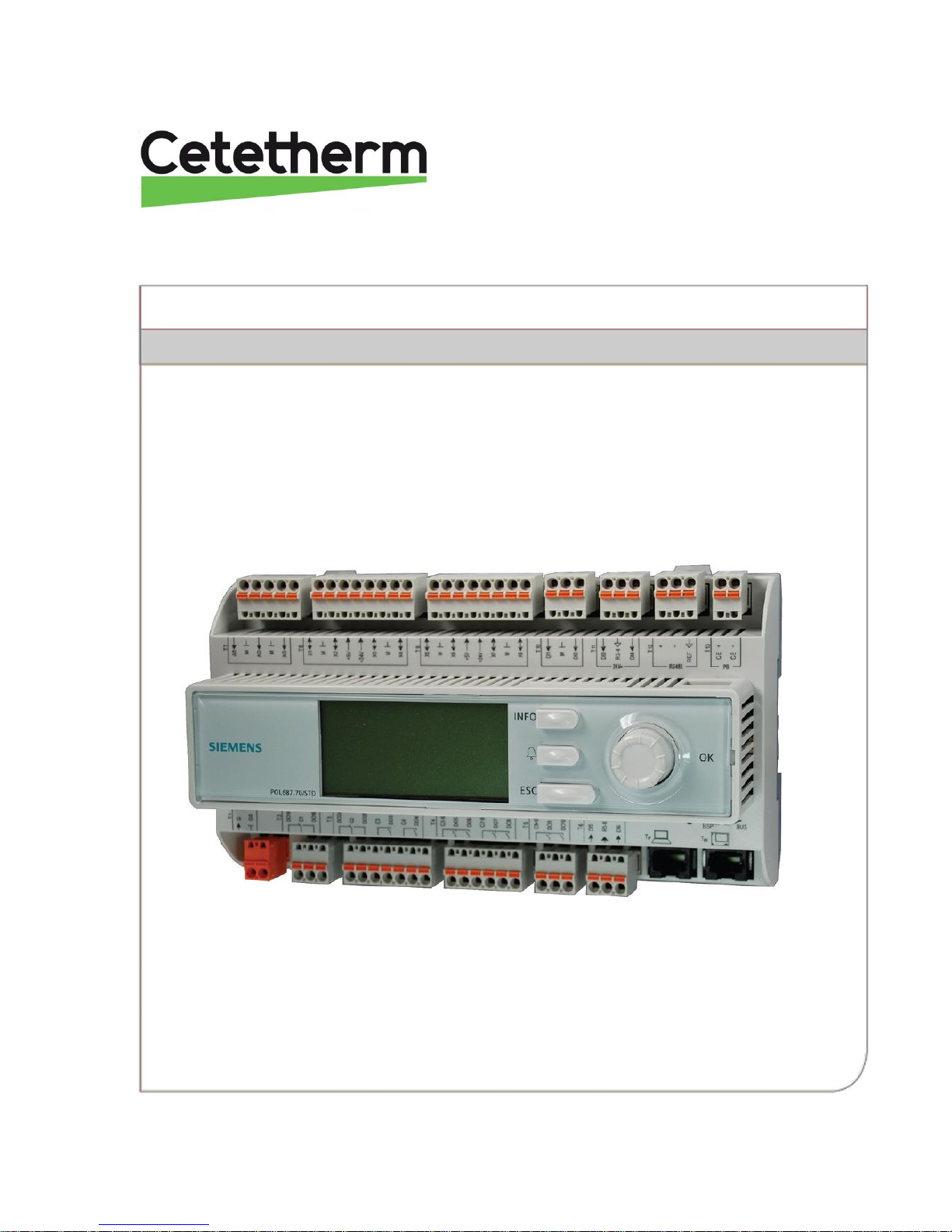
1.3 DDC1; Processing unit with Display and TCP/IP interface
DDC 1, Processing unit is fitted with an integral control panel where the plant values can be read and set.
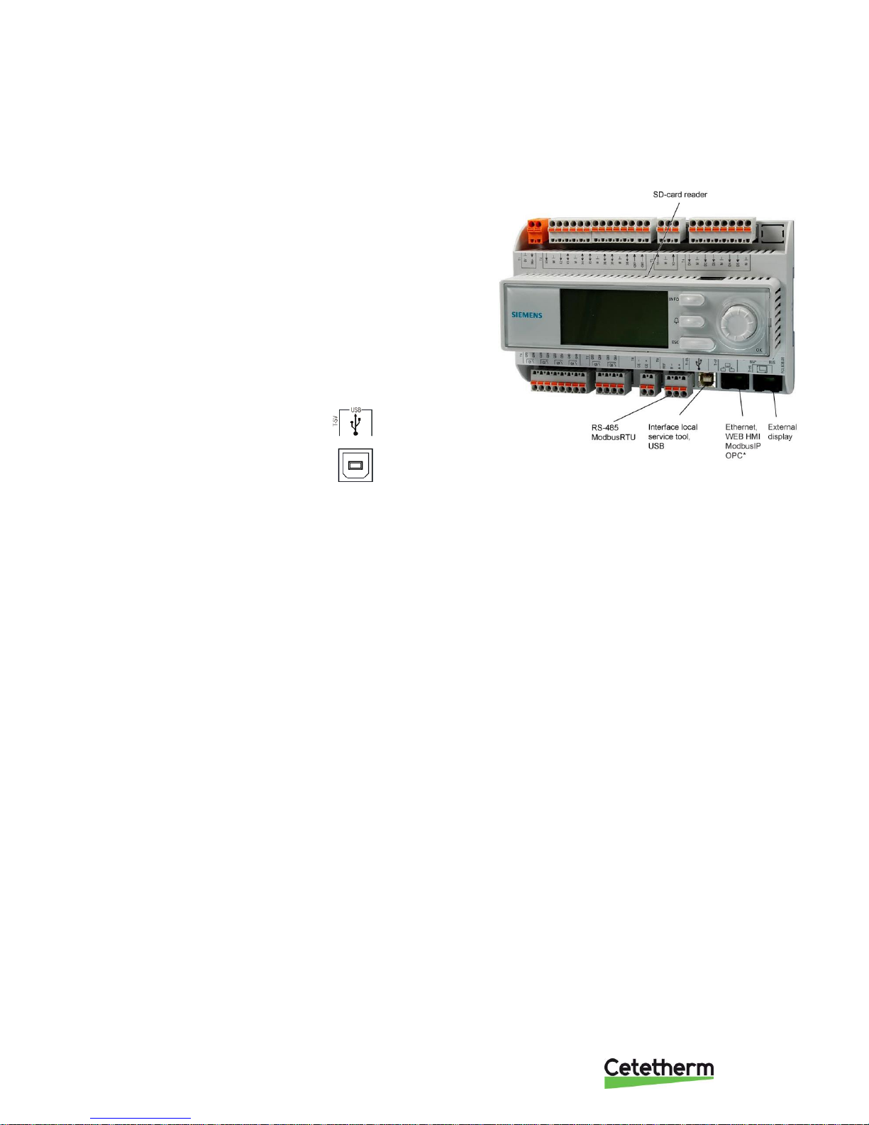
The processing unit has the following characteristics
• RS-485 ModBus RTU for third party bus
• full modem port RS-232 for remote service
• process bus for connecting room units and external
control panel (DPSU)
• up to three additional communication modules for
integration into the master system
• local service contact for control panel (RJ45) and PC
tools (USB)
• SD card to upgrade applications and software versions
• Ethernet service port (remote or local) via standard web
browser.
USB interface is of the type B output.
IQHeat
User manual
5
2 Communication principles
2.1 Internal Interface
A ModBus interface is always available in the processing unit. The RS485 interface can be defined as master
or slave; if both master and slave are required, a communication module must be connected with ModBus.
The TCP/IP interface is always the slave – both can be switched off.
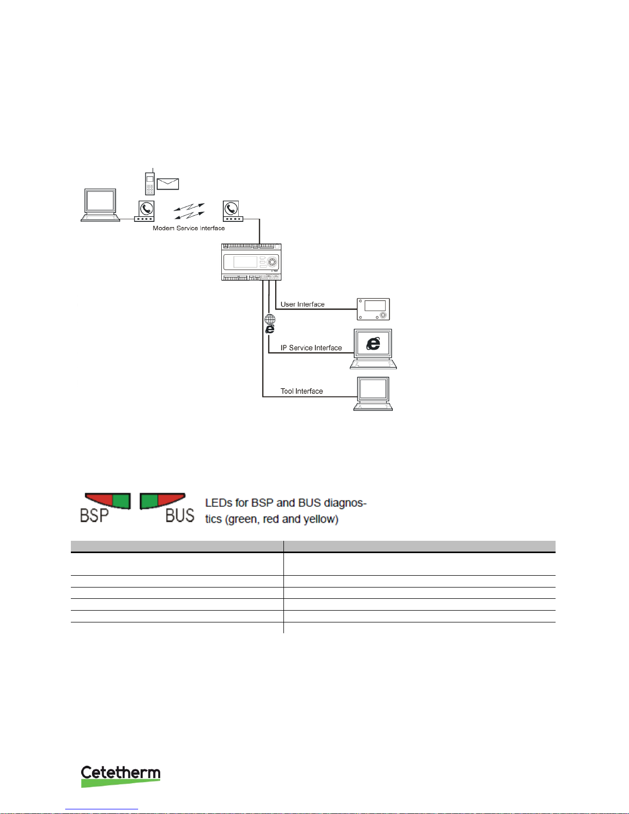
2.1.1 LEDs for BSP and BUS diagnostics
The processing unit has two LEDs, BSP and BUS, for diagnostics. The LEDs can light with three different
colours: yellow, green and red.
BSP indicates the status of the internal program in DDC1.
BUS indicates the status of the external communication.
BSP LEDs Start/Stop
Mode
Status LED BSP
Software update mode (download of
application or new software)
LED BSP lights every second alternating between red and
green
No application is loaded
Yellow LED flashing, lights 50 ms and off 1,000 ms
Application loaded but is not in operation
Yellow LED lights
Application is in operation
Green LED lights
BSP error (software error)
Red LED flashes at 2 Hz
Hardware error
Red LED lights
IQHeat
User manual
6
BUS LED
This LED only indicates the status of the integrated modem communication.
The LED does not indicate the status of internal communication (for input/output modules or communication
modules). This status is displayed on each expansion module.
Mode
Status LED BUS
No modem connected, or LED disconnected
Off
Modem connected and initiated, but
communication is not active
Yellow LED lights
Modem connected and communication is
active
Green LED lights
Modem connected but is defective (as well as
supply missing, initialisation is not possible)
Red LED lights
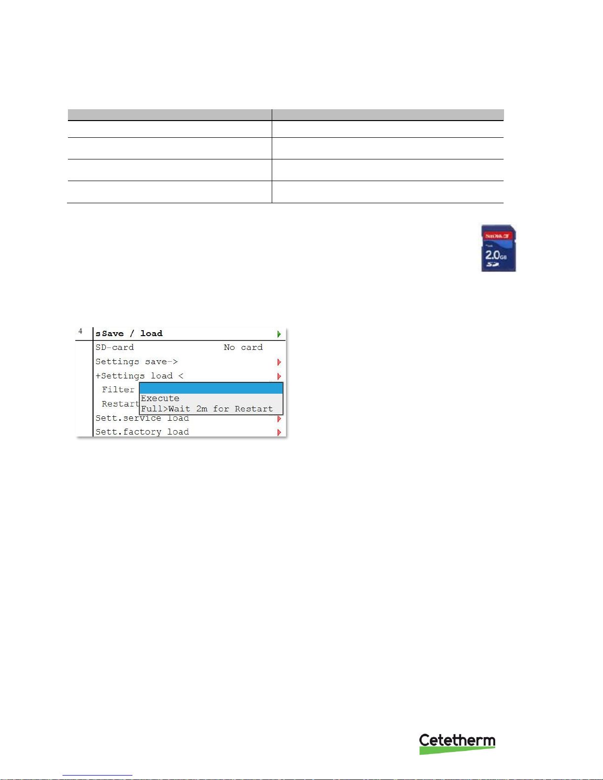
2.1.2 Upgrade with SD card
The processing unit can be upgraded with an SD card (FAT16 model, max 2GB). When
upgrading, connect the SD card to the memory card reader at the top right side of the
processing unit.
The upgrade requires logging in at service level.
There are two options for loading from SD card
• Apply - only control parameters loaded - recommended.
• Full - all settings given new values, including IP addresses and the like.
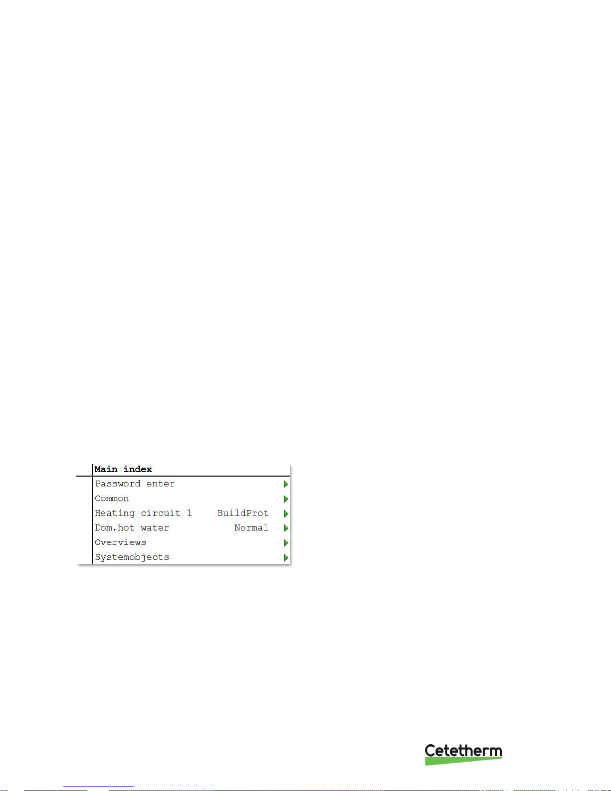
1. From the Main index select Systemobjects.
2. Select Save/load and press OK.
3. Select + Settings load < and press OK.
4. Select from
• Execute- recommended
• Full> Wait 2m for Restart - not recommended
5. From the menu Save/load
select Restart required!, press OK.
6. Select Execute and press OK.
7. The new settings take effect after restart.
NOTE: Connecting and disconnecting during read and write privileges may lead to data loss.
IQHeat
User manual
7
3 The control panel
All images in this document, in the menus in the control panel, are simply example images and should not be
used as a basis for settings.
The control panel is integrated into the processing unit.
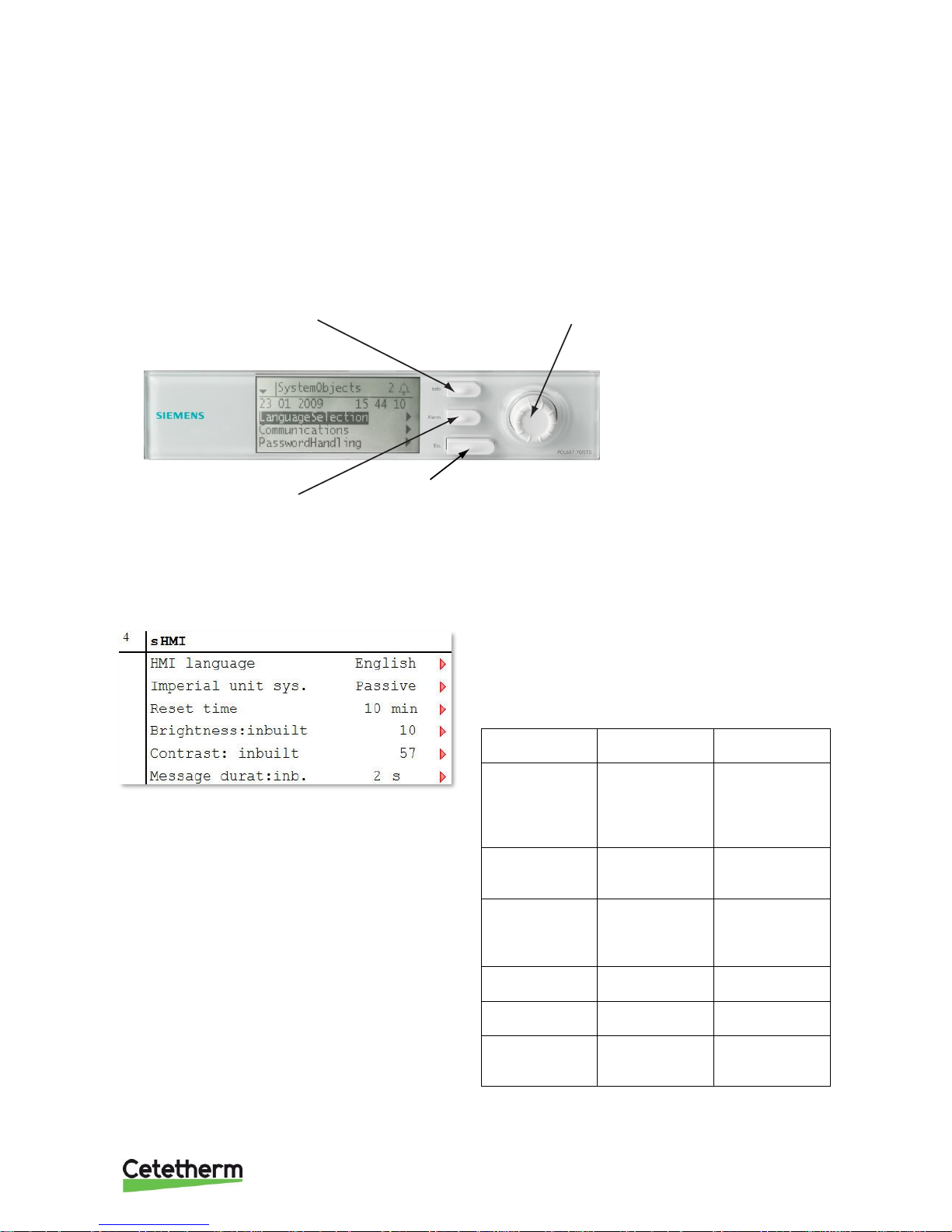
3.1 Display/HMI settings
1. Hold the ESC key down until the menu with HMI
settings appears or from Main Index choose
Systemobjects > HMI.
2. Select HMI settings to change and press OK.
3. Press OK to save the new setting.
4. Press ECS to return to the Main index.
Parameter
Settings
range
Explanation
HMI language
English
Svenska
Suomi
Polski
Select
Imperial unit
sys.
Passive
Active
Passive =
imperial units
e.g. °C.
Reset time
0…30 [min]
Login again is
necessary after
this time of
inactivates.
Brightness:
inbuilt
0…31
Display
brightness.
Contrast:
inbuilt
0…99
Display
contrast.
Message
durat: inb.
0…15 [s]
The time an
error message
is shown.
Info-button
Push to change between
Main overview and
Main index.
Select and OK knob
Turn to select menues, parameters and parameter
values.
Push: to exit the setting page and
adopt a changed value
Extended push: to go to the Password page
ESC-button
Push to go back to last active page or to cancel
Extended push: go back to the Main overvie w.
Alarm button with LED
Off: no alarm
Flashing: ongoing alarm
Permanently lit: Alarm ongoing and
acknowledged
Press to to change between alarm menus
IQHeat
User manual
8
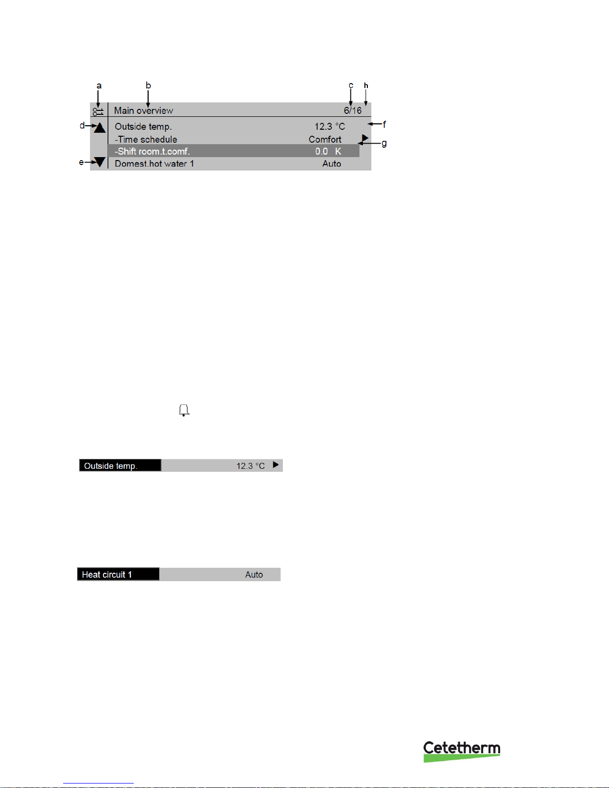
3.2 Display layout
a) current privilege level:
• no symbol - no privilege level
• one key - privilege level 6
• two keys - privilege level 4
• three keys - privilege level 2.
b) title for the displayed page
c) 7 - line number of the selected line
16 - total number of lines on the page
d) scroll arrow up - shows that the page contains additional lines above which appear when you scroll up
e) scroll arrow down - shows that the page contains additional lines below which appear when you scroll
down
f) the arrow means that there are underlying levels below this level to go to
g) current line
h) Alarm indication
3.3 Various line types
Navigation bar:
A navigation bar displays the option on a black
background when it is selected. The current value of
the option appears in front of the navigation arrow.
Navigation:
• select the line: turn the navigation dial
• go to underlying level: press the navigation dial
Viewing bar:
A Viewing bar displays the option on a black
background even when viewing in read-only mode.
The current value of the option appears.
IQHeat
User manual
9
Settings bar:
A setting bar shows the parameter name and the
current value on a black background.
Setting value:
• select the line: turn the navigation dial
• switch settings page: press the navigation dial
• set parameter value: turn the navigation dial
• close the settings page and apply the changed parameter value: press the navigation dial
• close the settings page without applying the changed parameter value: press ESC.
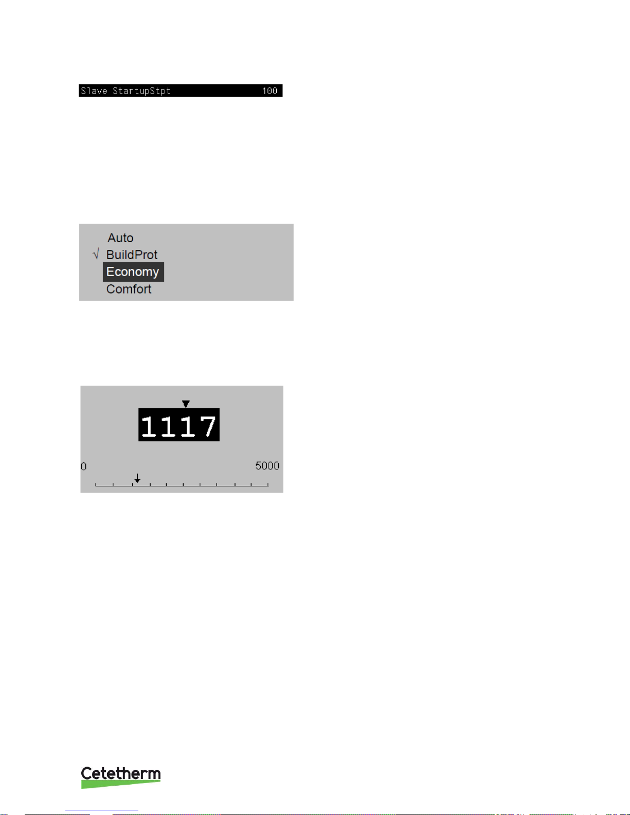
3.4 Setting parameters
When only one value is selectable:
The line with a tick in front (Fire Set point) shows the
set value
Change the value:
• select new value: turn the navigation dial
• apply the new value and close the settings page: press the navigation dial
• keep the old value and close the settings page: press the ESC key.
Setting analogue parameter values:
A scale displays the minimum and maximum values
that can be set.
Change set value:
• change the value below the arrow: turn the navigation dial
• apply the new value and close the settings page: press the navigation dial/OK
• keep the old value and close the settings page: press the ESC key.
IQHeat
User manual
10
4 Log in and set the clock
4.1 Password and login
The controller has password protection, allowing access to different menus.
NOTE: For security reasons must the factory set password be changed the first time the IQHeat starts up.
The following log-in levels are available:
All users: no log-in, no password required
• read access to all menus except the system parameters, configuration and detail menus
• read access to alarm lists and alarm history
End user, level 6, password 1000
• appears with one key in the upper left corner of the display
• all rights as for in "all users"
• read access to all menus except configuration menus
• write access to the main set points (Setpoints/Settings. > Setpoints)
• alarms and alarm history can be acknowledged and reset
Service level, level 4, password 2000
Used for configuring I/Os and system settings. Only qualified service personnel should make changes at this
level.
• appears with two keys in the upper left corner of the display
• all rights as for "End users"
• access to all menus except I/O configuration and system settings
OEM, level 2
• appears with three keys in the upper left corner of the display
• all rights as for System Administrator
• access to all menus and system settings.
Contact Cetetherm if there is a need to change anything at this level.
4.1.1 Log in
1. Keep the OK button pressed to access the
Password menu.
2. The first digit of four is marked with 0.
3. Turn the navigation dial until the desired number
appears.
4. Press OK to proceed to the next digit, continue
until all four are entered correctly and press OK.
The current key symbol will appear in the upper left
corner of the display window.
IQHeat
User manual
11
4.2 Time functions setting of time and date
The controller's clock includes the functions for summer and winter time changes and leap years. The clock has
a backup function to cover at least 24 hours of power cuts.
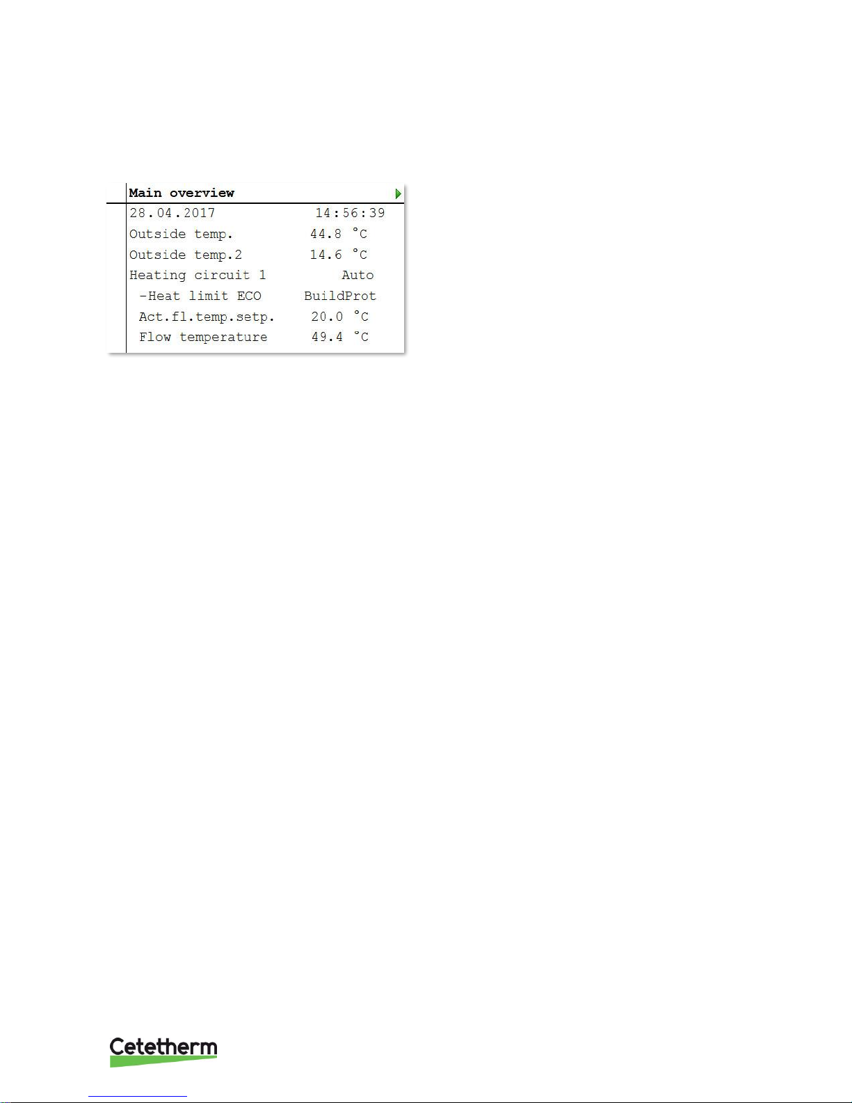
4.2.1 Reading date and time
1. Press Info to access Main overview.
2. The top line shows the set date and time.
4.2.2 Setting date and time
Requires login at end user level.
1. Press Info until the page with the date and time are displayed.
2. Move the cursor to the line for date and time.
3. Press OK to edit the day.
4. Set the correct day with the navigation dial, press OK to confirm and continue to edit the month and
year.
5. Continue to edit the hours, minutes and seconds in the same way.
6. Exit the menu with ESC.
IQHeat
User manual
12
5 Alarm management
The processing unit alerts for different situations. Alarms are indicated on the control display with the alarm
symbol .
Alarms are divided into three classes:
• A or 1 = Alarm, High
• B or 2 = Alarm, Low
• C or 3 = Alarm, Warning
Active alarms:
• alarm symbol in the display flashes
• alarm button on the control panel flashes
Acknowledged but still active alarm:
• alarm symbol in the display lights
• alarm button on the control panel lights
If a GSM modem is connected to the processing unit, an alarm is sent by text message to the specified
telephone number.
All incoming alarms generate an entry in the Alarm list and in Alarm history. When an alarm is no longer active,
it will disappear from the Alarm list.
The Alarm history contains the same information about the alarm as the Alarm list, i.e. time and date when the
alarm was sent. This also includes information on when the alarm was actioned. Incoming alarms are indicated
by a plus (+) before the name, while actioned are indicated by a minus (-). When the Alarm list is empty, there
should be as many + as – entries in the Alarm history.
5.1 Alarm list
The Alarm list contains all active alarms, acknowledged and unacknowledged. The Alarm list may contain up to
50 entries.
An alarm will remain in the Alarm list until it has been actioned.
The Alarm list menu has the option of selecting Acknowledge > Execute.
If Execute is selected, this means the alarm is confirmed, the Alarm button switches from flashing to steady
light. All information about the alarms remains.
1. Press the Alarm button once to see the details about the last alarm.
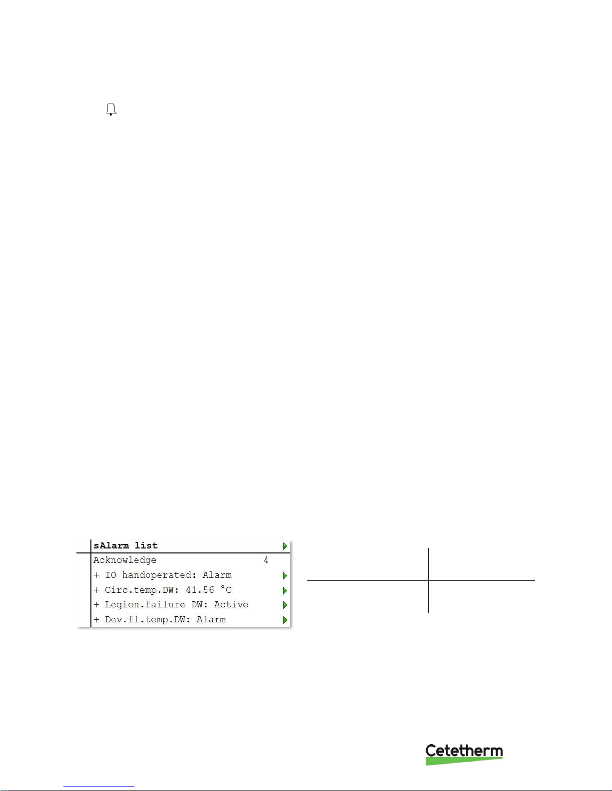
2. Press the Alarm button again to access the Alarm list.
3. A list of all active alarms now appears.
All active alarms correspond to an entry in the Alarm list.
Number of alarms that
are active.
In this example, 4.
+ Alarm name
Ex
+ IO in manual mode
Status
Alarm
IQHeat
User manual
13
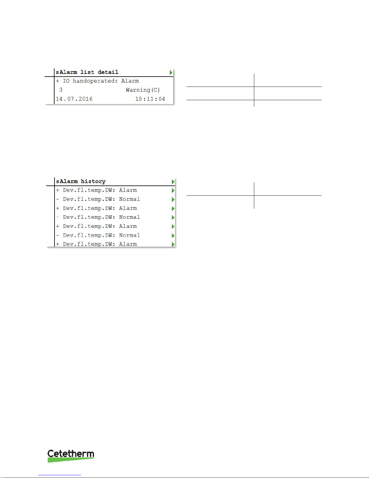
4. To see detailed information about an alarm, select the desired alarm by using the navigation dial and
press OK.
All active alarms have the following information included in the Alarm list.
+ Alarm name
Status
Alarm class
Alarm class
Date
Time
5.2 Alarm history
The Alarm history may contain up to 50 entries.
Each new alarm generates an entry in the Alarm history list. Incoming alarms are indicated by a plus (+) before
the name, while actioned alarms are indicated by a minus (-).
1. Press the Alarm button and choose Alarm history or press Alarm button three times to access the
Alarm history.
2. All alarms, both active and actioned, are now listed.
Number of alarms in the
list.
+/- Alarm name
Status
3. To see detailed information about an alarm, select the desired alarm by using the navigation dial and
press OK.
5.3 Settings
NOTE! Requires login at end user level
In the Alarming, under Advanced, you can see how many alarms there are in the Alarm list and Alarm history.
Here you can also set the sort order for how alarms are presented in the Alarm list and Alarm history. Each list is set
individually, so they may appear differently depending on the list that is opened.
Alarms can be sorted as:
• Sort 1:
▪ Time
▪ Obj.ID
▪ Priority
▪ State
• Sort 2:
▪ Time
▪ Obj.ID
▪ Priority
▪ State
• Descending order:
▪ Passive
▪ Active
NOTE: Resetting the Alarm list and/or Alarm history in the Advanced menu deletes the alarms from the lists.
The alarm indicator remains but the information about the alarm is deleted.
 Loading...