

Siemens IPC427, IPC477 19"", IPC477 15 Installation Manual
DOC023.98.90640
RTC Standardized Combined
(Siemens)
10/2018, Edition 2
Installation Manual
Installationsanleitung
Manuel d'installation
Manual de instalación
Manuale di installazione
Installatiehandleiding
Installationsvejledning
Manual de instalação
Návod k instalaci
Ръководство за инсталиране
Manual de instalare
Εγχειρίδιο εγκατάστασης
Inštalačná príručka
Namestitveni priročnik
Priručnik za ugradnju
Podręcznik instalacji
Installationshandbok
Kurulum Kılavuzu

English..............................................................................................................................3
Deutsch.......................................................................................................................... 16
Français......................................................................................................................... 29
Español.......................................................................................................................... 42
Italiano............................................................................................................................ 55
Nederlands....................................................................................................................68
Dansk..............................................................................................................................81
Português...................................................................................................................... 94
Čeština......................................................................................................................... 107
български................................................................................................................... 120
Română....................................................................................................................... 134
Ελληνικά...................................................................................................................... 147
Slovenský jazyk......................................................................................................... 160
Slovenski..................................................................................................................... 173
Hrvatski........................................................................................................................ 186
Polski............................................................................................................................ 199
Svenska....................................................................................................................... 212
Türkçe...........................................................................................................................225
2

Table of Contents
Specifications on page 3 Installation on page 7
General information on page 4 Maintenance on page 13
Legal Information
Manufacturer: Siemens AG
Distributor: Hach Lange GmbH
The translation of the manual is approved by the manufacturer.
Specifications
Specifications are subject to change without notice.
Note: Possible pixel errors in the TFT display are usual and do not show a defective instrument or display.
Note: Small malfunctions in the touchscreen sensor are usual and do not show a defective touchscreen or display.
Specification IPC427 IPC477 15" IPC477 19"
Processor Intel® Core™ i3-6102E
Processor (3M Cache,
1.9 GHz)
Intel® Core™ i3-6102E Processor (3M Cache, 1.9 GHz)
Flash memory Changeable mass storage CFAST 16 GB.
Interfaces Ethernet 3 x RJ45 (10/100/1000 Mbit/s), 4 × USB 3.0, 2 x DisplayPort, 2x RS232/485
Diagnostic LEDs PC ON/WD, RUN/STOP /
L1, ERROR / L2, MAINT /
L3
— —
Display — 1366 x 768 pixels 1366 x 768 pixels
Clock Internal clock with battery backup for time and date (battery replaceable)
Operating system Microsoft Windows® Embedded Standard 7 P
Power supply 24 VDC (–15%/+20%) 24 VDC (–15%/+20%)
Power consumption 24 W without USB devices
(including system
interfaces)
70 W (approximately) 78 W (approximately)
Dimensions (W x H x D)
(not cut out dimension)
262 x 133 x 55.5 /
64.5 mm (10.31 x 5.23 x
2.18 / 2.54 in.)
398 x 257 x 84.9mm
(15.67 x 10.11 x 3.34 in.)
464 x 294x 84.9 mm
(18.26 x 11.57 x 3.34 in.)
Weight 2.2 kg (4.85 lb) 5.2 kg (11.46 lb) 6.7 kg (14.77 lb)
Operating temperature 0 to 50°C (32 °F to 122 °F)
horizontal mounted with
CFast
0 to 50 °C (32 to 122 °F)
vertical mounted with
CFast
0 to 45 °C (32 to 113 °F)
vertical mounted with
CFast
Storage temperature –40 to 70 °C (–40 to
158 °F)
–20 to 60 °C (–4 to 140 °F)
Relative humidity Storage/transport between 5 to 95% non-condensing at 25 ° C (77 °F)
Vibration/shock
resistant
According to EN 60068-2-6/EN 60068-2-27
EMC immunity/emission According to EN 61000-6-2/EN 61000-6-4
Protection class IP20 Front side IP65, rear side IP20
Certification CE marked
English 3
General information
In no event will the manufacturer be liable for direct, indirect, special, incidental or consequential
damages resulting from any defect or omission in this manual. The manufacturer reserves the right to
make changes in this manual and the products it describes at any time, without notice or obligation.
Revised editions are found on the manufacturer’s website.
Safety information
N O T I C E
The manufacturer is not responsible for any damages due to misapplication or misuse of this product including,
without limitation, direct, incidental and consequential damages, and disclaims such damages to the full extent
permitted under applicable law. The user is solely responsible to identify critical application risks and install
appropriate mechanisms to protect processes during a possible equipment malfunction.
Please read this entire manual before unpacking, setting up or operating this equipment. Pay
attention to all danger and caution statements. Failure to do so could result in serious injury to the
operator or damage to the equipment.
Make sure that the protection provided by this equipment is not impaired. Do not use or install this
equipment in any manner other than that specified in this manual.
Use of hazard information
D A N G E R
Indicates a potentially or imminently hazardous situation which, if not avoided, will result in death or serious injury.
W A R N I N G
Indicates a potentially or imminently hazardous situation which, if not avoided, could result in death or serious
injury.
C A U T I O N
Indicates a potentially hazardous situation that may result in minor or moderate injury.
N O T I C E
Indicates a situation which, if not avoided, may cause damage to the instrument. Information that requires special
emphasis.
Precautionary labels
Read all labels and tags attached to the instrument. Personal injury or damage to the instrument
could occur if not observed. A symbol on the instrument is referenced in the manual with a
precautionary statement.
This is the safety alert symbol. Obey all safety messages that follow this symbol to avoid potential
injury. If on the instrument, refer to the instruction manual for operation or safety information.
This symbol indicates that a risk of electrical shock and/or electrocution exists.
This symbol indicates the presence of devices sensitive to Electro-static Discharge (ESD) and
indicates that care must be taken to prevent damage with the equipment.
4 English
Electrical equipment marked with this symbol may not be disposed of in European domestic or public
disposal systems. Return old or end-of-life equipment to the manufacturer for disposal at no charge to
the user.
This symbol, when noted on the product, identifies the location of a fuse or current limiting device.
This symbol indicates that the marked item requires a protective earth connection. If the instrument is
not supplied with a ground plug on a cord, make the protective earth connection to the protective
conductor terminal.
IPC427E overview
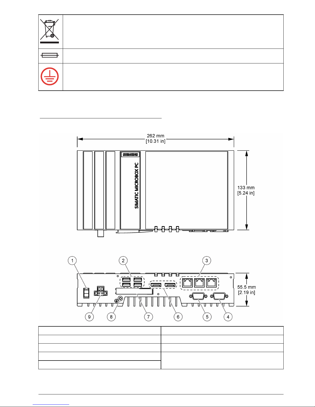
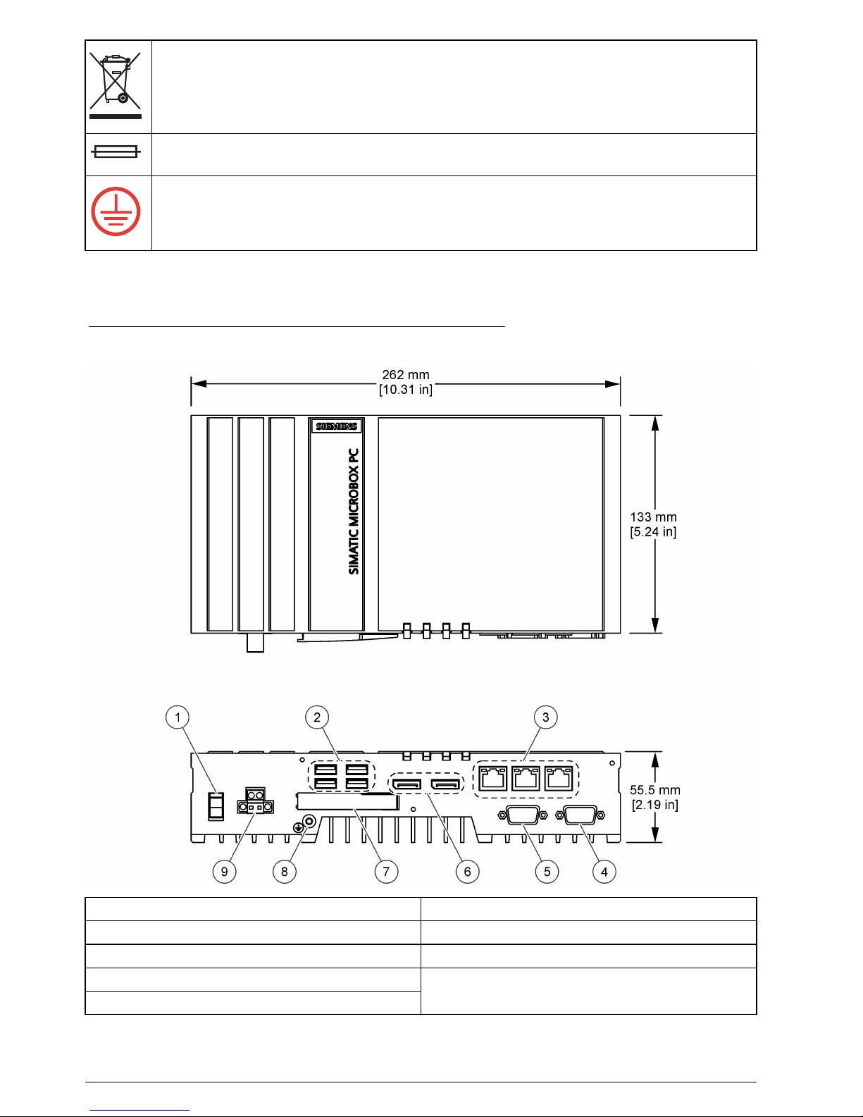
Figure 1 shows the IPC427E dimensions and connectors.
Figure 1 IPC427E dimensions and connectors
1 On / Off switch 6 Display connector (2x)
2 USB connector (4x) 7 CFast card slot with cover
3 RJ45 Ethernet connector (3x) 8 Protective earth connector
4 COM2 serial connector (optional) 9 Power supply, 24 VDC
5 COM1 serial connector (optional)
English 5
IPC477 overview
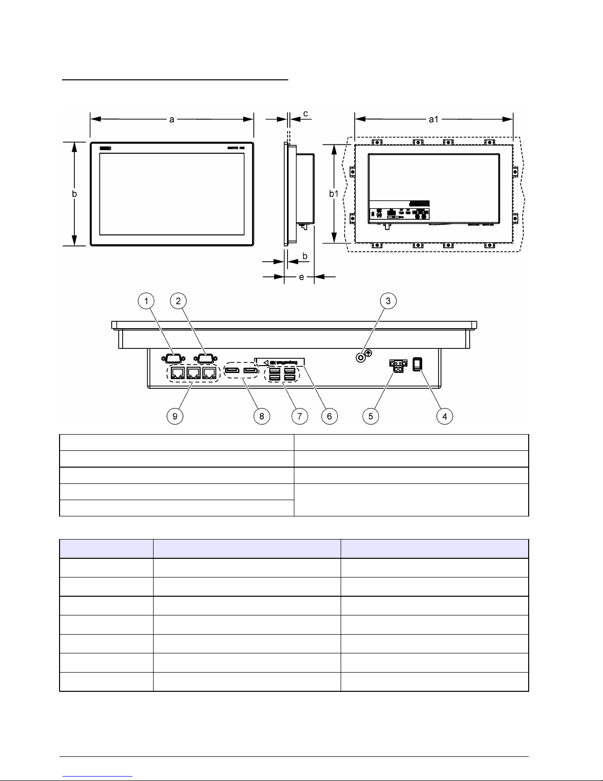
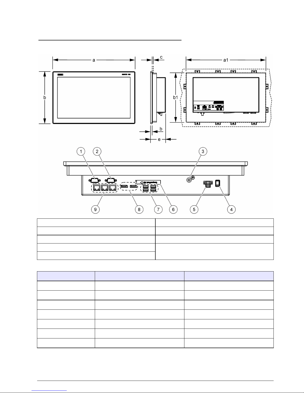
Figure 2 shows the IPC477 XX" overview and connectors. Refer to Table 1 for the dimensions and
cut out dimensions for the IPC477 XX".
Figure 2 IPC477 dimensions and connectors
1 COM2 serial connector (optional) 6 CFast card slot with cover
2 COM1 serial connector (optional) 7 USB connector (4x)
3 Protective earth connector 8 Display connector (2x)
4 On / Off switch 9 RJ45 Ethernet connector (3x)
5 Power supply, 24 VDC
Table 1 IPC477 XX" dimensions
Dimension IPC477 15" Multi-Touch IPC477 19" Multi-Touch
a 398 mm (15.66 in.) 477 mm (18.78 in.)
b 257 mm (10.11 in.) 294 mm (11.57 in.)
c 2–6 mm (0.08–0.24 in.) 2–6 mm (0.08–0.24 in.)
d 6.2 mm (0.24 in.) 6.2 mm (0.24 in.)
e 84.9 mm (3.34 in.) 84.9 mm (3.34 in.)
a1 (cut out) 382 mm (15.0 in.) 448 mm (17.6 in.)
b1 (cut out) 241 mm (9.5 in.) 278 mm (11.0 in.)
6 English
Installation
C A U T I O N
Multiple hazards. Only qualified personnel must conduct the tasks described in this section of the
document.
IPC427E mounting
W A R N I N G
Personal injury hazard. Make sure that the wall mounting is able to hold 4 times the weight of the
equipment.
N O T I C E
The device is only approved for operation in closed rooms.
The temperatures given are valid for devices with a CFast card, without PCI cards and installed in
restricted access locations (RAL).
Refer to Figure 3 for installation on a DIN rail.
English 7
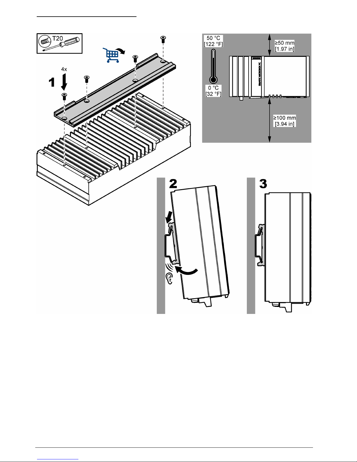
Figure 3 Installation on a DIN rail
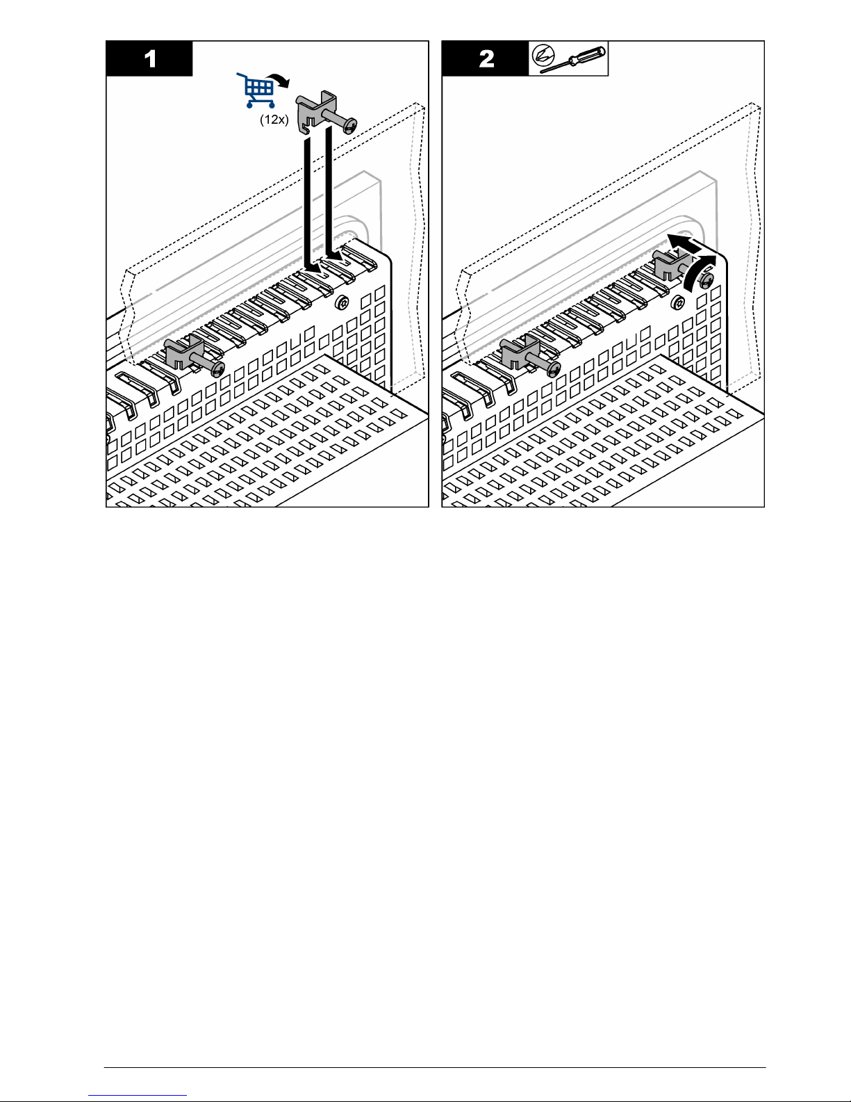
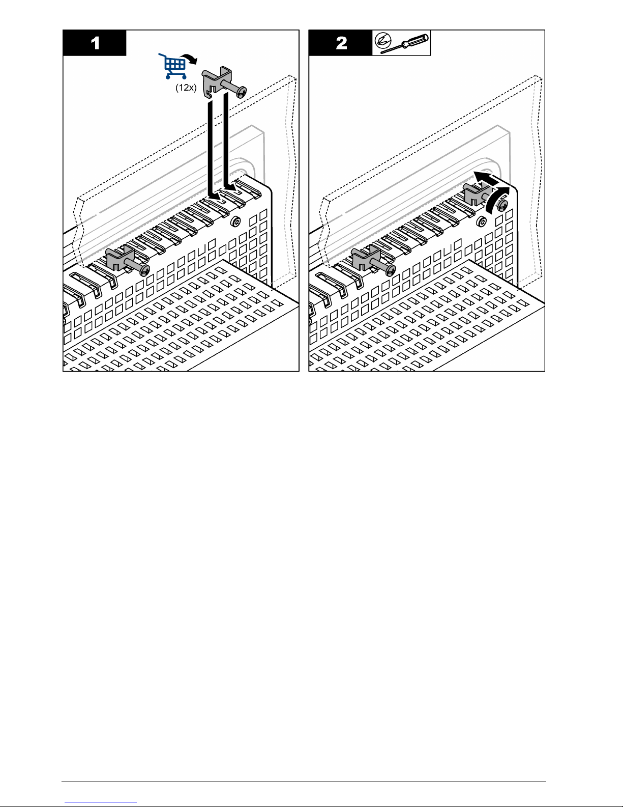
IPC477 mounting
Make an opening in the control cabinet. For the correct cut out dimensions, refer to Table 1
on page 6. To install the IPC477 XX" in the control cabinet, refer to the illustrated steps that follow
and Figure 4.
8
English
English 9
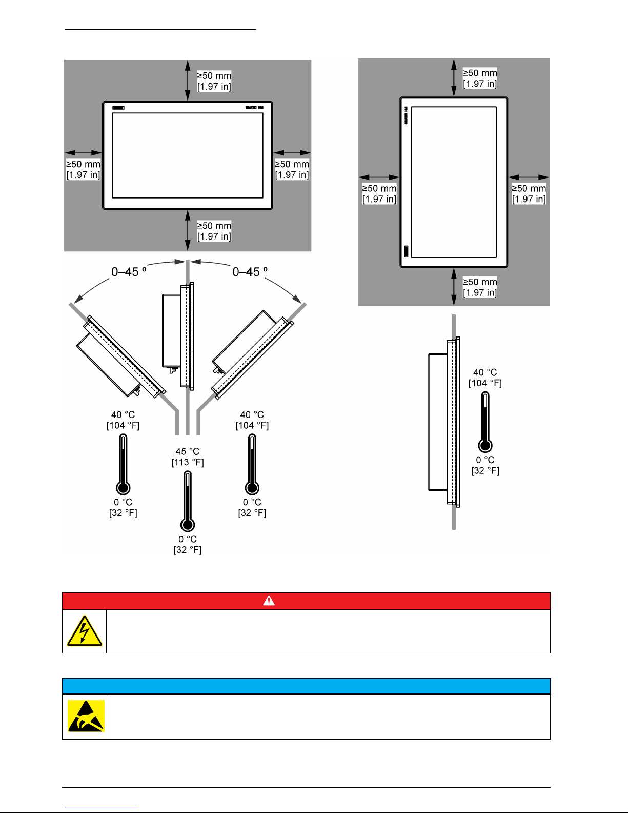
Figure 4 IPC477 mounting variantes
Electrical installation
D A N G E R
Electrocution hazard. Always remove power to the instrument before making electrical connections.
Electrostatic discharge (ESD) considerations
N O T I C E
Potential Instrument Damage. Delicate internal electronic components can be damaged by static
electricity, resulting in degraded performance or eventual failure.
Refer to the steps in this procedure to prevent ESD damage to the instrument:
10
English
• Touch an earth-grounded metal surface such as the chassis of an instrument, a metal conduit or
pipe to discharge static electricity from the body.
• Avoid excessive movement. Transport static-sensitive components in anti-static containers or
packages.
• Wear a wrist strap connected by a wire to earth ground.
• Work in a static-safe area with anti-static floor pads and work bench pads.
IPC427 power supply
N O T I C E
Potential Instrument Damage. Delicate internal electronic components can be damaged by static electricity,
resulting in degraded performance or eventual failure.
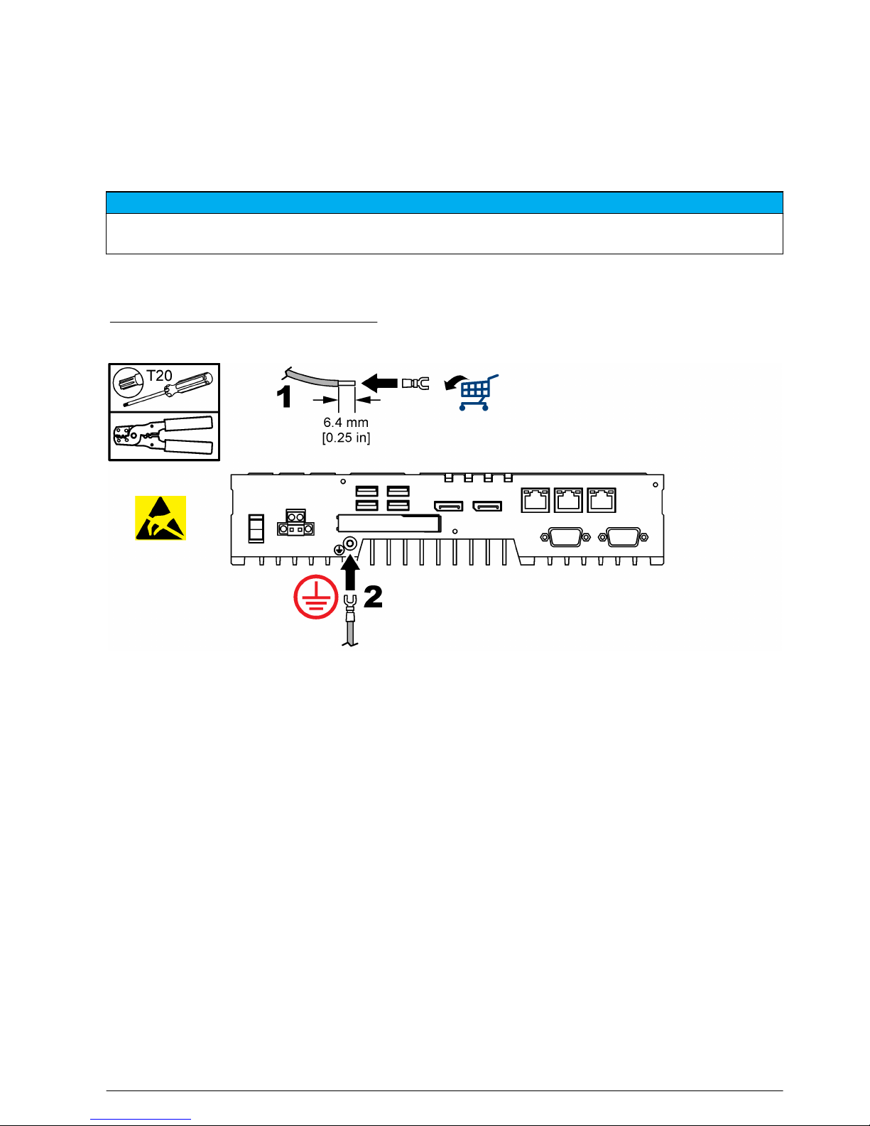
Connect the device only to a 24 VDC power supply that agrees the requirements of safety extra low
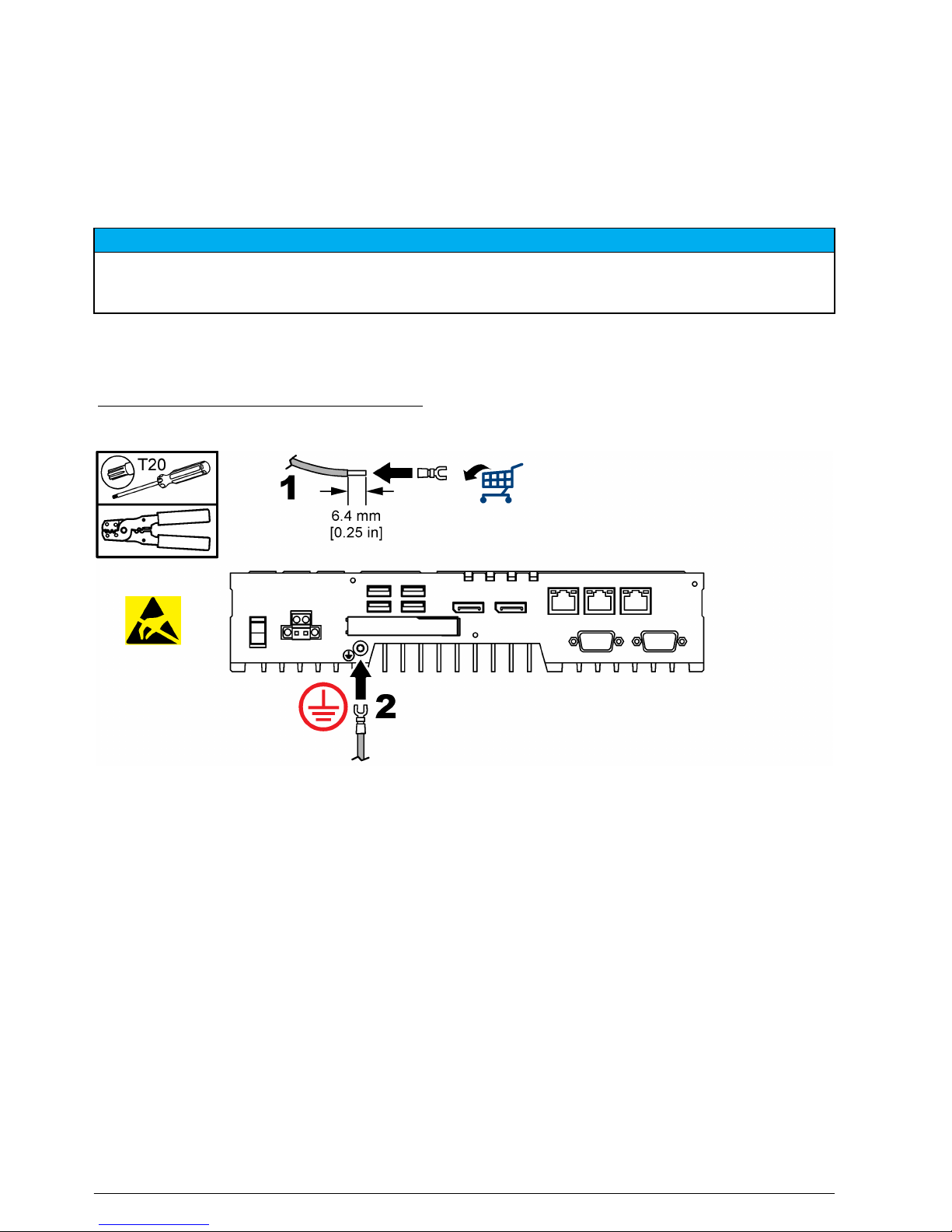
voltage (SELV) according to IEC/EN/DIN EN/UL 60950-1. Refer to Figure 5 to connect protective
earth. Refer to Figure 6 to connect to a power supply.
Figure 5 Connect to protective earth
English 11
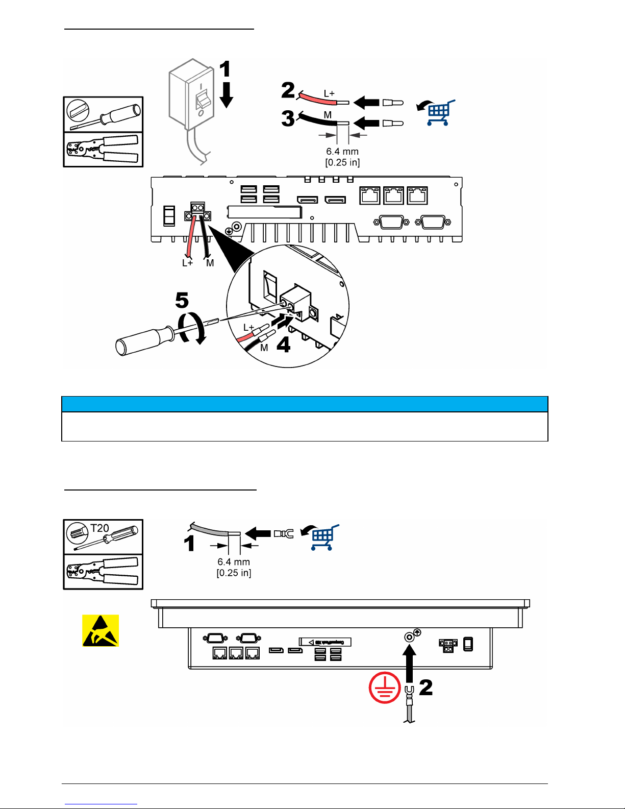
Figure 6 Connect to a power supply
ICP477 power supply
N O T I C E
Potential Instrument Damage. Delicate internal electronic components can be damaged by static electricity,
resulting in degraded performance or eventual failure.
Connect the device only to a 24 VDC power supply that agrees the requirements of safety extra low
voltage (SELV) according to IEC/EN/DIN EN/UL 60950-1. Refer to Figure 7 to connect protective
earth. Refer to Figure 8 to connect to a power supply.
Figure 7 Connect to protective earth
12 English
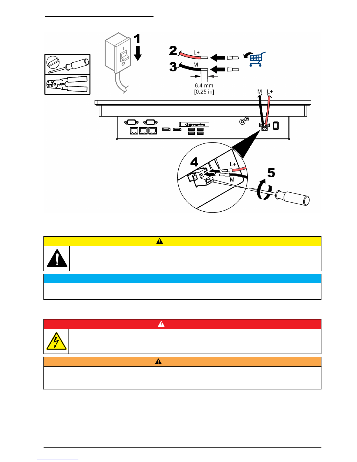
Figure 8 Connect to a power supply
Maintenance
C A U T I O N
Multiple hazards. Only qualified personnel must conduct the tasks described in this section of the
document.
N O T I C E
Do not disassemble the instrument for maintenance. If the internal components must be cleaned or repaired,
contact the manufacturer.
Backup battery replacement
D A N G E R
Electrocution hazard. Remove power from the instrument before doing maintenance or service
activities.
W A R N I N G
Explosion hazard. Incorrect battery installation can cause the release of explosive gases. Be sure that the
batteries are of the same approved chemical type and are inserted in the correct orientation. Do not mix new and
used batteries.
Note: Make sure to replace the battery in less than 30 seconds to prevent the data loss of date and time settings. If
date and time settings are erased the device time will not be synchronized. Timer-controlled programs will stop or
will operate at the wrong time.
Set the device time again.
The service life of a backup battery is approximately 5 to 8 years, based on the operating conditions.
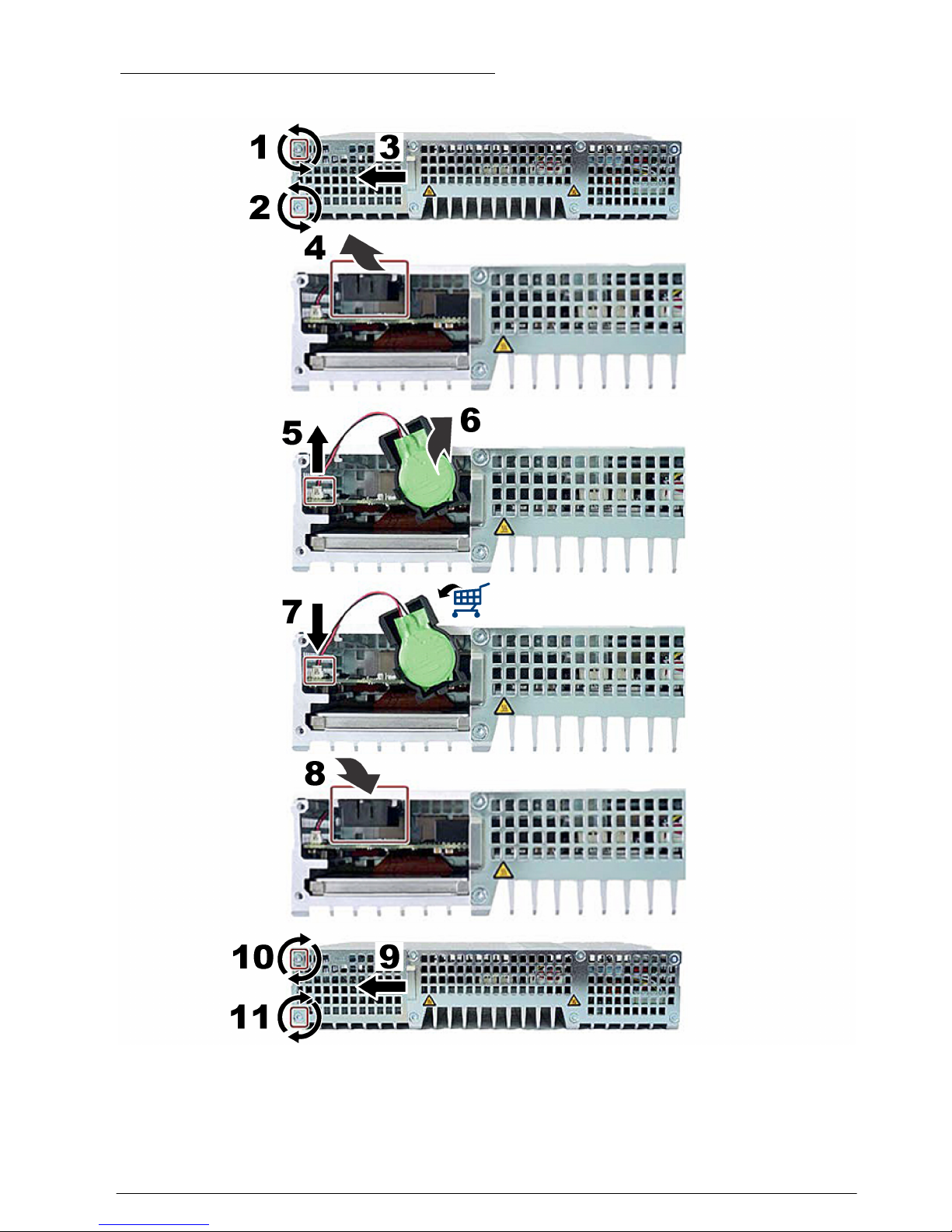
To replace the battery, refer to the illustrated steps that follow.
English
13
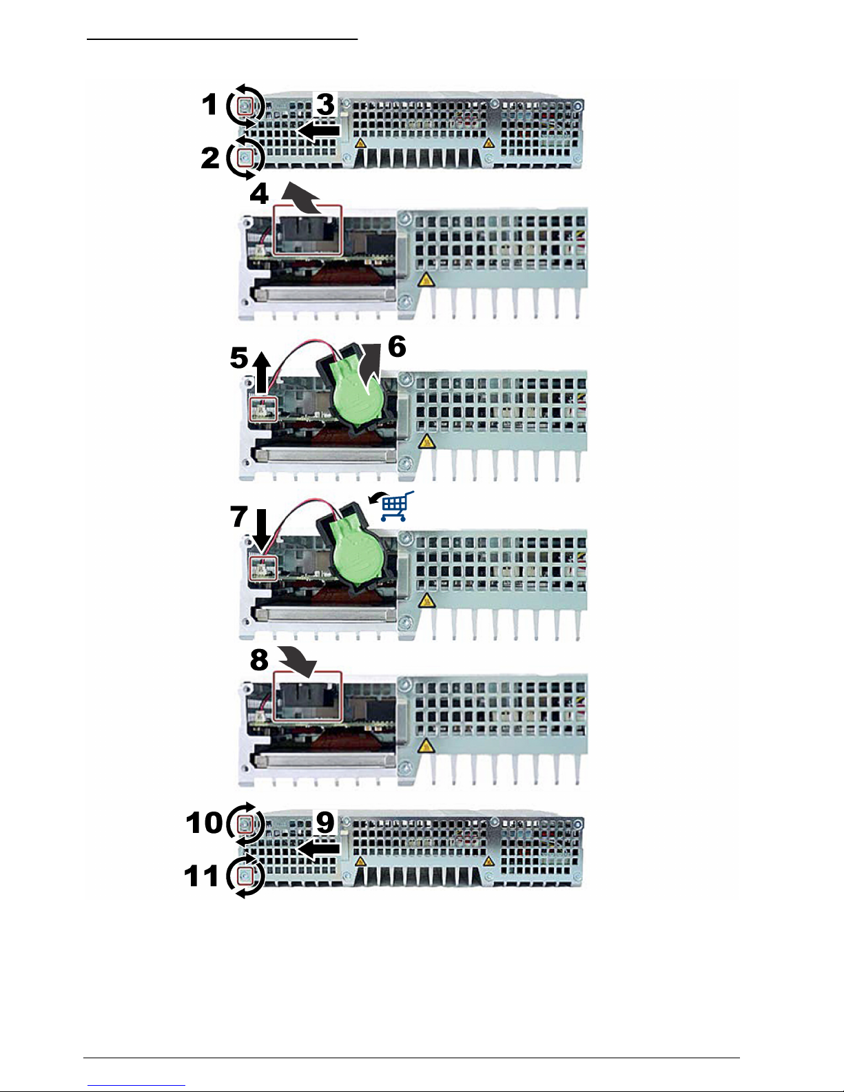
Figure 9 IPC427E battery replacement
14 English
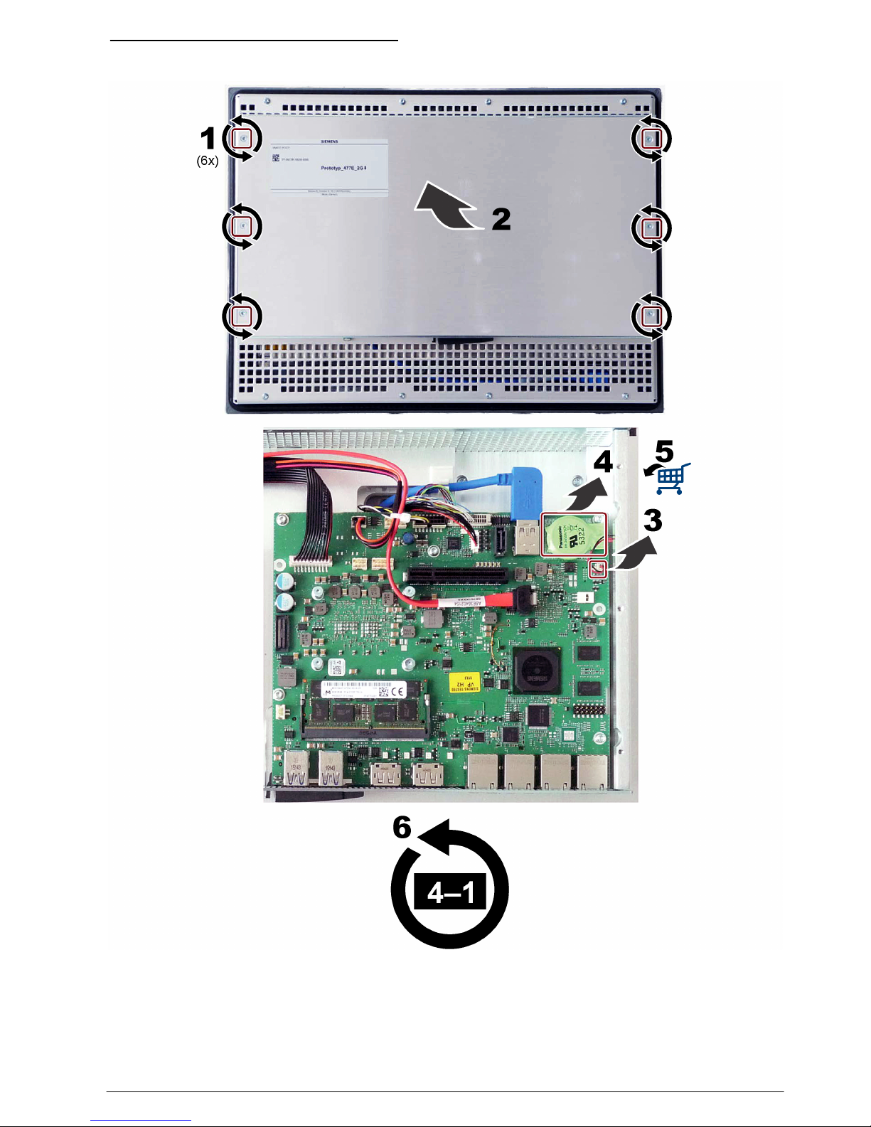
Figure 10 IPC477E battery replacement
English 15

Inhaltsverzeichnis
Technische Daten auf Seite 16 Installation auf Seite 20
Allgemeine Informationen auf Seite 17 Wartung auf Seite 26
Rechtliche Informationen
Hersteller: Siemens AG
Vertreiber: Hach Lange GmbH
Die Übersetzung des Handbuchs ist vom Hersteller freigegeben.
Technische Daten
Änderungen vorbehalten.
Hinweis: Mögliche Pixelfehler im TFT-Display sind normal und kein Defekt im Gerät oder Bildschirm.
Hinweis: Kleine Fehlfunktionen im Touchscreen-Sensor sind normal und kein Defekt im Gerät oder Bildschirm.
Technische Daten IPC427 IPC477 15" IPC477 19"
Prozessor Intel® Core™ i3-6102E-
Prozessor (3 MB Cache,
1,9 GHz)
Intel® Core™ i3-6102E-Prozessor (3 MB Cache,
1,9 GHz)
Flash-Speicher wechselbarer Massenspeicher CFAST, 16 GB.
Schnittstellen 3 x RJ45 Ethernet (10/100/1000 Mbit/s), 4 x USB 3.0, 2 x Bildschirm-Port,
2 x RS232/485
Diagnose-LEDs PC ON/WD, RUN/STOP / L1,
ERROR / L2, MAINT / L3
— —
Anzeige — 1366 x 768 Pixel 1366 x 768 Pixel
Takt Interner Takt mit Batterie-Backup für Zeit und Datum (Batterie austauschbar)
Betriebssystem Microsoft Windows® Embedded Standard 7 P
Netzteil 24 V Gleichstrom
(-15 %/+20 %)
24 V Gleichstrom (-15 %/+20 %)
Leistungsaufnahme 24 W ohne USB-Geräte
(einschließlich
Systemschnittstellen)
70 W (ca.) 78 W (ca.)
Abmessungen (B x H x T)
(keine
Ausschnittabmessungen)
262 x 133 x 55,5/64,5 mm
(10,31 x 5,23 x 2,18/2,54")
398 x 257 x 84,9 mm
(15,67 x 10,11 x 3,34")
464 x 294 x 84,9 mm
(18,26 x 11,57 x 3,34")
Gewicht 2,2 kg 5,2 kg 6,7 kg
Betriebstemperatur 0 bis 50 °C bei horizontaler
Montage mit CFast
0 bis 50 °C bei vertikaler
Montage mit CFast
0 bis 45 °C bei vertikaler
Montage mit CFast
Lagertemperatur -40 bis 70 °C -20 bis 60 °C
Relative Luftfeuchtigkeit Lagerung/Transport zwischen 5 und 95 %, nicht kondensierend bei 25 °C
Vibrations-/Stoßfestigkeit Gemäß EN 60068-2-6/EN 60068-2-27
EMV-Störfestigkeit Gemäß EN 61000-6-2/EN 61000-6-4
Schutzklasse IP20 Vorderseite IP65, Rückseite IP20
Zertifizierung CE-Zeichen
16 Deutsch
Allgemeine Informationen
Der Hersteller ist nicht verantwortlich für direkte, indirekte, versehentliche oder Folgeschäden, die
aus Fehlern oder Unterlassungen in diesem Handbuch entstanden. Der Hersteller behält sich
jederzeit und ohne vorherige Ankündigung oder Verpflichtung das Recht auf Verbesserungen an
diesem Handbuch und den hierin beschriebenen Produkten vor. Überarbeitete Ausgaben der
Bedienungsanleitung sind auf der Hersteller-Webseite erhältlich.
Sicherheitshinweise
H I N W E I S
Der Hersteller ist nicht für Schäden verantwortlich, die durch Fehlanwendung oder Missbrauch dieses Produkts
entstehen, einschließlich, aber ohne Beschränkung auf direkte, zufällige oder Folgeschäden, und lehnt jegliche
Haftung im gesetzlich zulässigen Umfang ab. Der Benutzer ist selbst dafür verantwortlich, schwerwiegende
Anwendungsrisiken zu erkennen und erforderliche Maßnahmen durchzuführen, um die Prozesse im Fall von
möglichen Gerätefehlern zu schützen.
Bitte lesen Sie dieses Handbuch komplett durch, bevor Sie dieses Gerät auspacken, aufstellen oder
bedienen. Beachten Sie alle Gefahren- und Warnhinweise. Nichtbeachtung kann zu schweren
Verletzungen des Bedieners oder Schäden am Gerät führen.
Stellen Sie sicher, dass die durch dieses Messgerät bereitgestellte Sicherheit nicht beeinträchtigt
wird. Verwenden bzw. installieren Sie das Messsystem nur wie in diesem Handbuch beschrieben.
Bedeutung von Gefahrenhinweisen
G E F A H R
Kennzeichnet eine mögliche oder drohende Gefahrensituation, die, wenn sie nicht vermieden wird, zum Tod oder
zu schweren Verletzungen führt.
W A R N U N G
Kennzeichnet eine mögliche oder drohende Gefahrensituation, die, wenn sie nicht vermieden wird, zum Tod oder
zu schweren Verletzungen führen kann.
V O R S I C H T
Kennzeichnet eine mögliche Gefahrensituation, die zu geringeren oder moderaten Verletzungen führen kann.
H I N W E I S
Kennzeichnet eine Situation, die, wenn sie nicht vermieden wird, das Gerät beschädigen kann. Informationen, die
besonders beachtet werden müssen.
Warnhinweise
Lesen Sie alle am Gerät angebrachten Aufkleber und Hinweise. Nichtbeachtung kann Verletzungen
oder Beschädigungen des Geräts zur Folge haben. Im Handbuch wird in Form von Warnhinweisen
auf die am Gerät angebrachten Symbole verwiesen.
Dies ist das Sicherheits-Warnsymbol. Befolgen Sie alle Sicherheitshinweise im Zusammenhang mit
diesem Symbol, um Verletzungen zu vermeiden. Wenn es am Gerät angebracht ist, beachten Sie die
Betriebs- oder Sicherheitsinformationen im Handbuch.
Dieses Symbol weist auf die Gefahr eines elektrischen Schlages hin, der tödlich sein kann.
Dieses Symbol zeigt das Vorhandensein von Geräten an, die empfindlich auf elektrostatische
Entladung reagieren. Es müssen Vorsichtsmaßnahmen getroffen werden, um die Geräte nicht zu
beschädigen.
Deutsch 17
Elektrogeräte, die mit diesem Symbol gekennzeichnet sind, dürfen nicht im normalen öffentlichen
Abfallsystem entsorgt werden. Senden Sie Altgeräte an den Hersteller zurück. Dieser entsorgt die
Geräte ohne Kosten für den Benutzer.
Wenn sich dieses Symbol auf dem Produkt befindet, gibt es die Position einer Sicherung oder eines
Strombegrenzers an.
Dieses Symbol weist darauf hin, dass das gekennzeichnete Teil an einen Erdungsschutzleiter
angeschlossen werden muss. Wenn das Instrument nicht über einen Netzstecker an einem Kabel
verfügt, verbinden Sie die Schutzerde mit der Schutzleiterklemme.
Übersicht über IPC427E
Abbildung 1 zeigt die Abmessungen und Anschlüsse des IPC427E.
Abbildung 1 Abmessungen und Anschlüsse des IPC427E
1 Ein-/Aus-Schalter 6 Bildschirmanschluss (2x)
2 USB-Anschluss (4x) 7 CFast-Kartensteckplatz mit Abdeckung
3 RJ45 Ethernet-Anschluss (3x) 8 Schutzleiteranschluss
4 COM2 serieller Anschluss (optional) 9 Netzteil, 24 VDC
5 COM1 serieller Anschluss (optional)
18 Deutsch
Übersicht über IPC477
Abbildung 2 zeigt einen Überblick und Anschlüsse von IPC477 XX". Beachten Sie Tabelle 1
hinsichtlich der Abmessungen und Ausschnittabmessungen für den IPC477 XX".
Abbildung 2 Abmessungen und Anschlüsse des IPC477
1 COM2 serieller Anschluss (optional) 6 CFast-Kartensteckplatz mit Abdeckung
2 COM1 serieller Anschluss (optional) 7 USB-Anschluss (4x)
3 Schutzleiteranschluss 8 Bildschirmanschluss (2x)
4 Ein-/Aus-Schalter 9 RJ45 Ethernet-Anschluss (3x)
5 Netzteil, 24 VDC
Tabelle 1 Abmessungen des IPC477 XX"
Abmessungen IPC477 15" Multi-Touch IPC477 19" Multi-Touch
a 398 mm (15,66") 477 mm (18,78")
b 257 mm (10,11") 294 mm (11,57")
c 2 - 6 mm (0,08 - 0,24") 2 - 6 mm (0,08 - 0,24")
d 6,2 mm (0,24") 6,2 mm (0,24")
e 84,9 mm (3,34") 84,9 mm (3,34")
a1 (Ausschnitt) 382 mm (15,0") 448 mm (17,6")
b1 (Ausschnitt) 241 mm (9,5") 278 mm (11,0")
Deutsch 19
Installation
V O R S I C H T
Mehrere Gefahren. Nur qualifiziertes Personal sollte die in diesem Kapitel des Dokuments
beschriebenen Aufgaben durchführen.
Montage des IPC427E
W A R N U N G
Verletzungsgefahr. Vergewissern Sie sich, dass die Wandbefestigung das vierfache Gewicht der
Ausrüstung tragen kann.
H I N W E I S
Das Gerät ist nur für den Betrieb in geschlossenen Räumen zugelassen.
Die angegebenen Temperaturen gelten für Geräte mit einer CFast-Karte ohne PCI-Karten, die in
abgeschlossenen Betriebsräumen (RAL) installiert sind.
Beachten Sie Abbildung 3, um eine DIN-Schiene zu installieren.
20 Deutsch
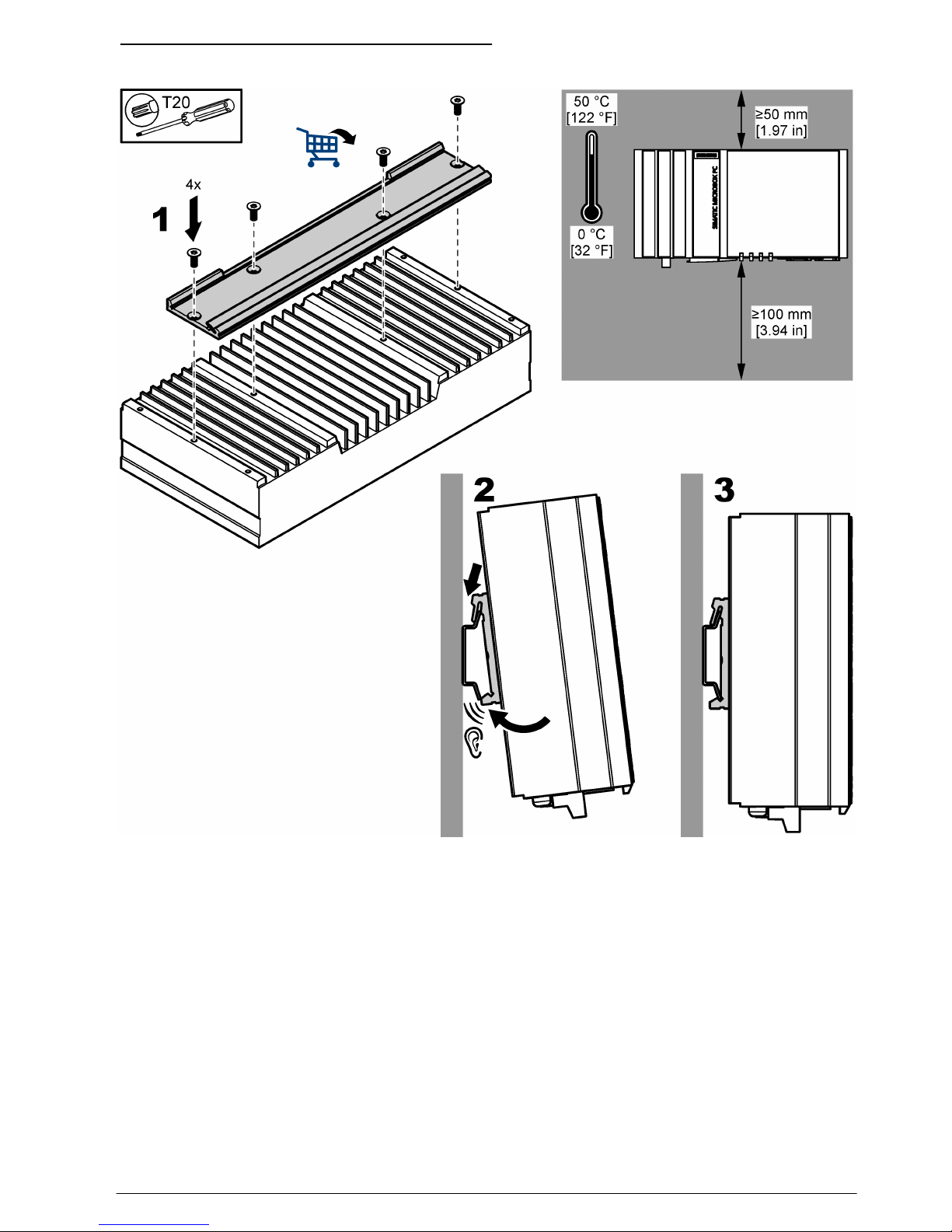
Abbildung 3 Installation auf einer DIN-Schiene
Montage des IPC477
Öffnen Sie den Schaltschrank. Die korrekten Ausschnittabmessungen finden Sie in Tabelle 1
auf Seite 19. Zur Installation des IPC477 XX" im Schaltschrank beachten Sie die nachfolgend
abgebildeten Schritte und Abbildung 4.
Deutsch
21
22 Deutsch
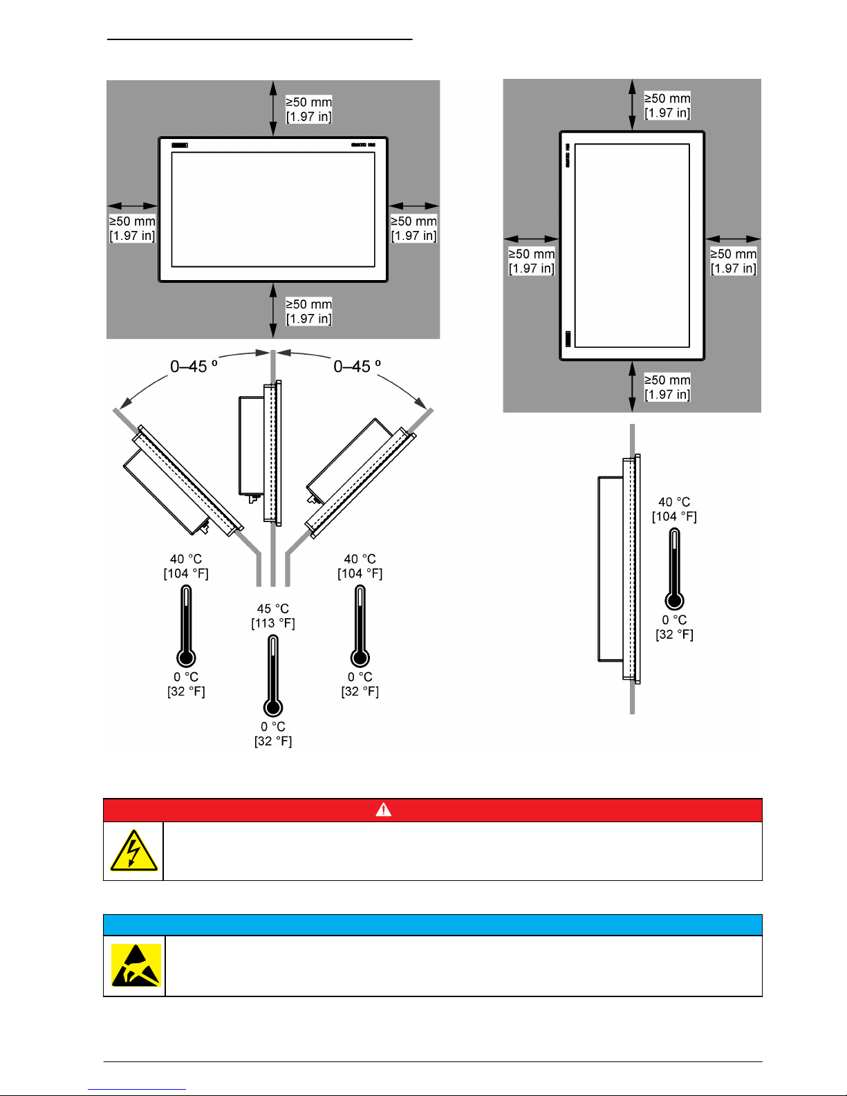
Abbildung 4 Montagevarianten des IPC477
Elektrische Installation
G E F A H R
Lebensgefahr durch Stromschlag. Trennen Sie das Gerät immer von der Spannungsversorgung, bevor
Sie elektrische Anschlüsse herstellen.
Hinweise zur Vermeidung elektrostatischer Entladungen (ESE)
H I N W E I S
Möglicher Geräteschaden Empfindliche interne elektronische Bauteile können durch statische
Elektrizität beschädigt werden, wobei dann das Gerät mit verminderter Leistung funktioniert oder
schließlich ganz ausfällt.
Befolgen Sie die Schritte in dieser Anleitung, um ESD-Schäden am Gerät zu vermeiden.
Deutsch
23
• Berühren Sie eine geerdete Metallfläche, wie beispielsweise des Gehäuse eines Geräts, einen
Metallleiter oder ein Rohr, um statische Elektrizität vom Körper abzuleiten.
• Vermeiden Sie übermäßige Bewegung. Verwenden Sie zum Transport von Komponenten, die
gegen statische Aufladungen empfindlich sind, Antistatikfolie oder antistatische Behälter.
• Tragen Sie ein Armband, das mit einem geerdeten Leiter verbunden ist.
• Arbeiten Sie in einem elektrostatisch sicheren Bereich mit antistatischen Fußbodenbelägen und
Arbeitsunterlagen
IPC427 – Netzteil
H I N W E I S
Möglicher Geräteschaden. Die empfindlichen elektronischen Komponenten im Geräteinneren können durch
statische Elektrizität beschädigt werden, was zu Beeinträchtigungen der Geräteleistung bis hin zum Ausfall des
Gerätes führen kann.
Verbinden Sie das Gerät nur mit einem 24 VDC-Netzteil, das den Anforderungen der
Schutzkleinspannung (SELV) gemäß IEC/EN/DIN EN/UL 60950-1 entspricht. Angaben zum
Anschließen an Schutzerde finden Sie in Abbildung 5. Angaben zum Anschließen an das Netzteil
finden Sie in Abbildung 6.
Abbildung 5 Anschließen an Schutzerde
24 Deutsch
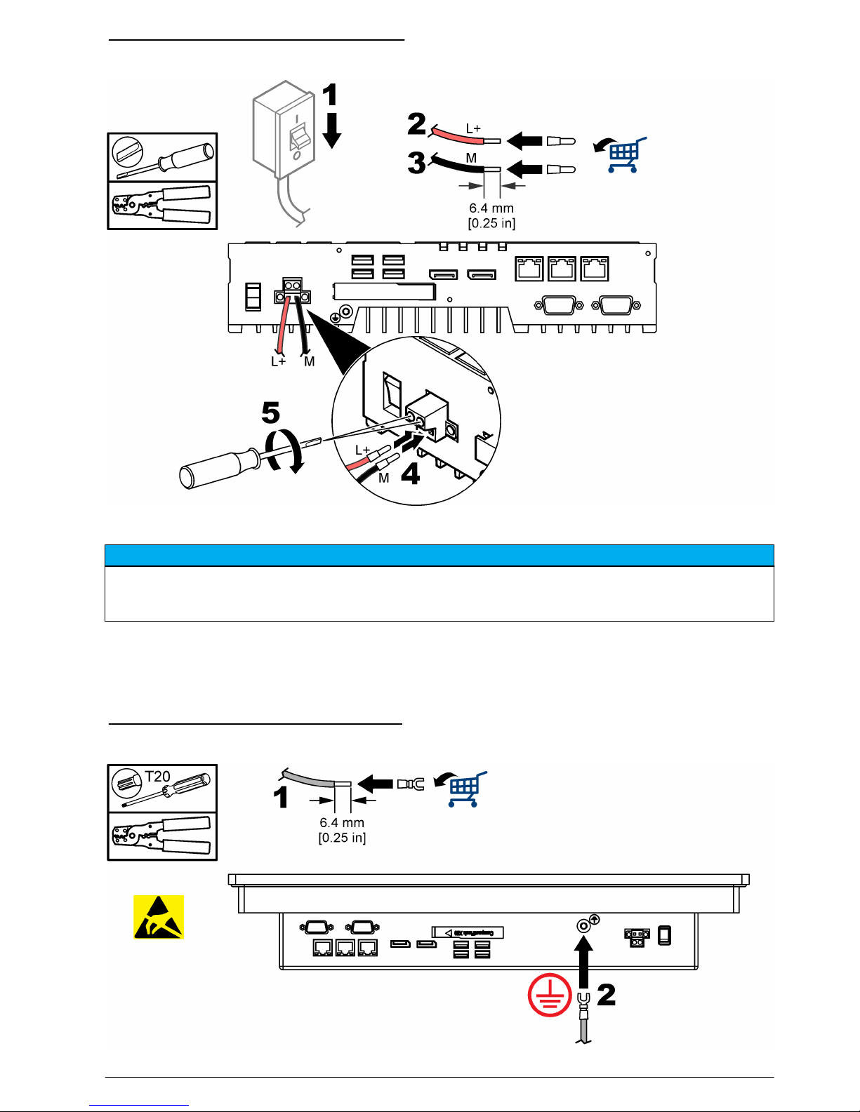
Abbildung 6 Anschließen an das Netzteil
ICP477 – Netzteil
H I N W E I S
Möglicher Geräteschaden. Die empfindlichen elektronischen Komponenten im Geräteinneren können durch
statische Elektrizität beschädigt werden, was zu Beeinträchtigungen der Geräteleistung bis hin zum Ausfall des
Gerätes führen kann.
Verbinden Sie das Gerät nur mit einem 24 VDC-Netzteil, das den Anforderungen der
Schutzkleinspannung (SELV) gemäß IEC/EN/DIN EN/UL 60950-1 entspricht. Angaben zum
Anschließen an Schutzerde finden Sie in Abbildung 7. Angaben zum Anschließen an das Netzteil
finden Sie in Abbildung 8.
Abbildung 7 Anschließen an Schutzerde
Deutsch 25

Abbildung 8 Anschließen an das Netzteil
Wartung
V O R S I C H T
Mehrere Gefahren. Nur qualifiziertes Personal sollte die in diesem Kapitel des Dokuments
beschriebenen Aufgaben durchführen.
H I N W E I S
Do not disassemble the instrument for maintenance. If the internal components must be cleaned or repaired,
contact the manufacturer.
Austausch der Sicherungsbatterie
G E F A H R
Lebensgefahr durch Stromschlag. Trennen Sie vor der Durchführung von Wartungs- oder
Instandhaltungsmaßnahmen die Stromzufuhr vom Gerät.
W A R N U N G
Explosionsgefahr. Das unsachgemäße Einlegen von Batterien kann zur Freisetzung explosiver Gase führen.
Vergewissern Sie sich, dass Sie Batterien mit dem zulässigen Chemikalientyp verwenden und dass sie mit der
korrekten Polung eingelegt wurden. Verwenden Sie nicht alte und neue Batterien zusammen.
Hinweis: Stellen Sie sicher, dass die Batterie in weniger als 30 Sekunden ausgetauscht wird, um den Datenverlust
von Einstellungen für Datum und Uhrzeit zu vermeiden. Wenn Einstellungen für Datum und Uhrzeit gelöscht
werden, wird die Gerätezeit nicht synchronisiert. Timer-gesteuerte Programme werden beendet oder zur falschen
Zeit ausgeführt.
Stellen Sie die Gerätezeit wieder ein.
Die Betriebsdauer einer Sicherungsbatterie beträgt je nach Betriebsbedingungen 5 bis 8 Jahre.
26
Deutsch
Informationen zum Austauschen der Batterie finden Sie in den folgenden illustrierten Schritten.
Abbildung 9 IPC427E – Austausch der Batterie
Deutsch 27
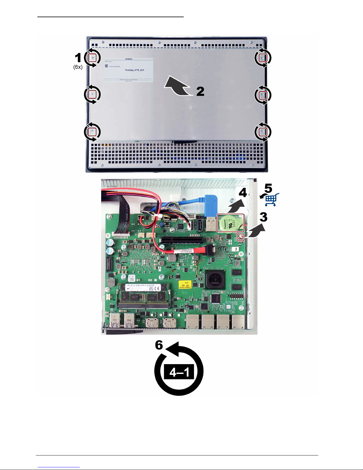
Abbildung 10 IPC477E – Austausch der Batterie
28 Deutsch

Table des matières
Caractéristiques techniques à la page 29 Installation à la page 33
Généralités à la page 30 Maintenance à la page 39
Informations légales
Fabricant : Siemens AG
Distributeur : Hach Lange GmbH
La traduction du manuel est approuvée par le fabricant.
Caractéristiques techniques
Ces caractéristiques sont susceptibles d'être modifiées sans avis préalable.
Remarque : L'écran peut présenter des pixels morts : cela ne signifie pas que l'instrument ou l'écran est
défectueux.
Remarque : Le capteur tactile peut présenter de petits dysfonctionnements : cela ne signifie pas que l'écran tactile
est défectueux.
Caractéristiques IPC427 IPC477 15" IPC477 19"
Processeur Processeur Intel® Core
™
i3-6102E (3 Mo Cache,
1,9 GHz)
Processeur Intel® Core™ i3-6102E (3 Mo Cache, 1,9 GHz)
Mémoire Flash Mémoire de masse modifiable CFAST 16 Go.
Interfaces Ethernet 3 x RJ45 (10/100/1000 Mbit/s), 4 × USB 3.0, 2 x port d'écran, 2x RS232/485
Voyants de
diagnostic
PC MARCHE/WD,
EXECUTER/ARRET/ L1,
ERREUR / L2, MAINT / L3
— —
Ecran — 1366 x 768 pixels 1366 x 768 pixels
Horloge Horloge interne avec sauvegarde par pile de l'heure et de la date (pile remplaçable)
Système
d'exploitation
Microsoft Windows® Embedded Standard 7 P
Alimentation 24 V CC (-15 %/ +20 %) 24 V CC (-15 %/ +20 %)
Consommation
électrique
24 W sans périphériques
USB (y compris les interfaces
du système)
70 W (environ) 78 W (environ)
Dimensions
(L x H x P) (pas
dimension de
coupe)
262 x 133 x 55,5 / 64,5 mm
(10,31 x 5,23 x 2,18 / 2,54 po)
398 x 257 x 84,9 mm
(15,67 x 10,11 x 3,34 po)
464 x 294 x 84,9 mm (18,26 x 11,57 x 3,34 po)
Poids 2,2 kg (4,85 lb) 5,2 kg (11,46 lb) 6,7 kg (14,77 lb)
Température de
fonctionnement
0 à 50 °C (32 °F à 122 °F)
horizontal monté avec CFast
0 à 50 °C (32 °F à
122 °F) vertical monté
avec CFast
0 à 45 °C (32 °F à 113 °F) vertical monté avec
CFast
Température de
stockage
-40 à 70 °C (-40 à 158 °F) –20 à 60 °C (–4 à 140 °F)
Humidité relative Stockage/transport entre 5 et 95 % sans condensation à 25 °C (77 °F)
Résiste aux
vibrations et aux
chocs
Conforme à EN 60068-2-6/EN 60068-2-27
Français 29
Caractéristiques IPC427 IPC477 15" IPC477 19"
Immunité/émission
CEM
Conforme à EN 61000-6-2/EN 61000-6-4
Classe de
protection
IP20 Face avant IP 65, face arrière IP 20
Certification Marquage CE
Généralités
En aucun cas le constructeur ne saurait être responsable des dommages directs, indirects, spéciaux,
accessoires ou consécutifs résultant d'un défaut ou d'une omission dans ce manuel. Le constructeur
se réserve le droit d'apporter des modifications à ce manuel et aux produits décrits à tout moment,
sans avertissement ni obligation. Les éditions révisées se trouvent sur le site Internet du fabricant.
Consignes de sécurité
A V I S
Le fabricant décline toute responsabilité quant aux dégâts liés à une application ou un usage inappropriés de ce
produit, y compris, sans toutefois s'y limiter, des dommages directs ou indirects, ainsi que des dommages
consécutifs, et rejette toute responsabilité quant à ces dommages dans la mesure où la loi applicable le permet.
L'utilisateur est seul responsable de la vérification des risques d'application critiques et de la mise en place de
mécanismes de protection des processus en cas de défaillance de l'équipement.
Veuillez lire l'ensemble du manuel avant le déballage, la configuration ou la mise en fonctionnement
de cet appareil. Respectez toutes les déclarations de prudence et d'attention. Le non-respect de
cette procédure peut conduire à des blessures graves de l'opérateur ou à des dégâts sur le matériel.
Assurez-vous que la protection fournie avec cet appareil n'est pas défaillante. N'utilisez ni n'installez
cet appareil d'une façon différente de celle décrite dans ce manuel.
Interprétation des indications de risques
D A N G E R
Indique une situation de danger potentiel ou imminent qui, si elle n'est pas évitée, entraîne des blessures graves,
voire mortelles.
A V E R T I S S E M E N T
Indique une situation de danger potentiel ou imminent qui, si elle n'est pas évitée, peut entraîner des blessures
graves, voire mortelles.
A T T E N T I O N
Indique une situation de danger potentiel qui peut entraîner des blessures mineures ou légères.
A V I S
Indique une situation qui, si elle n'est pas évitée, peut occasionner l'endommagement du matériel. Informations
nécessitant une attention particulière.
30 Français
 Loading...