

Page 1

_
_
_
_
_
_
_
_
_
_
_
_
_
_
_
_
_
_
_
SIMATIC Industrial PC SIMATIC IPC427C
SIMATIC
Industrial PC
SIMATIC IPC427C
Operating Instructions
Introduction
Safety Instructions
_____________
_____________
Description
_____________
Application planning
_____________
Installing/mounting
_____________
Connecting
_____________
Commissioning
_____________
Integration into an
Automation System
_____________
Functions
_____________
Expansions and
Configurations
_____________
Maintenance and Service
_____________
Alarm, error and system
messages
_____________
Troubleshooting/FAQs
_____________
Technical specifications
_____________
Dimension drawings
_____________
Detailed descriptions
_____________
Appendix
_____________
ESD guidelines
_____________
List of abbreviations
_____________
1
2
3
4
5
6
7
8
9
10
11
12
13
14
15
16
A
B
C
04/2009
A5E02414743-01
Page 2

Legal information
Legal information
Warning notice system
This manual contains notices you have to observe in order to ensure your personal safety, as well as to prevent
damage to property. The notices referring to your personal safety are highlighted in the manual by a safety alert
symbol, notices referring only to property damage have no safety alert symbol. These notices shown below are
graded according to the degree of danger.
DANGER
indicates that death or severe personal injury will result if proper precautions are not taken.
WARNING
indicates that death or severe personal injury may result if proper precautions are not taken.
CAUTION
with a safety alert symbol, indicates that minor personal injury can result if proper precautions are not taken.
CAUTION
without a safety alert symbol, indicates that property damage can result if proper precautions are not taken.
NOTICE
indicates that an unintended result or situation can occur if the corresponding information is not taken into
account.
If more than one degree of danger is present, the warning notice representing the highest degree of danger will
be used. A notice warning of injury to persons with a safety alert symbol may also include a warning relating to
property damage.
Qualified Personnel
The device/system may only be set up and used in conjunction with this documentation. Commissioning and
operation of a device/system may only be performed by qualified personnel. Within the context of the safety notes
in this documentation qualified persons are defined as persons who are authorized to commission, ground and
label devices, systems and circuits in accordance with established safety practices and standards.
Proper use of Siemens products
Note the following:
WARNING
Siemens products may only be used for the applications described in the catalog and in the relevant technical
documentation. If products and components from other manufacturers are used, these must be recommended
or approved by Siemens. Proper transport, storage, installation, assembly, commissioning, operation and
maintenance are required to ensure that the products operate safely and without any problems. The permissible
ambient conditions must be adhered to. The information in the relevant documentation must be observed.
Trademarks
All names identified by ® are registered trademarks of the Siemens AG. The remaining trademarks in this
publication may be trademarks whose use by third parties for their own purposes could violate the rights of the
owner.
Disclaimer of Liability
We have reviewed the contents of this publication to ensure consistency with the hardware and software
described. Since variance cannot be precluded entirely, we cannot guarantee full consistency. However, the
information in this publication is reviewed regularly and any necessary corrections are included in subsequent
editions.
Siemens AG
Industry Sector
Postfach 48 48
90026 NÜRNBERG
GERMANY
A5E02414743-01
Ⓟ 04/2009
Copyright © Siemens AG 2009.
Technical data subject to change
Page 3

Table of contents
1 Introduction................................................................................................................................................
1.1 Preface...........................................................................................................................................
1.2 Guideline to the Operating Instructions .........................................................................................
2 Safety Instructions.....................................................................................................................................
2.1 General safety instructions ............................................................................................................
3 Description...............................................................................................................................................
3.1 Overview ......................................................................................................................................
3.2 Applications..................................................................................................................................
3.3 Features.......................................................................................................................................
3.4 Windows Embedded Standard 2009 ...........................................................................................
3.5 Design..........................................................................................................................................
3.5.1 External Design............................................................................................................................
3.5.2 Connection components ..............................................................................................................
3.5.3 Operator controls .........................................................................................................................
3.5.4 Status displays.............................................................................................................................
4 Application planning.................................................................................................................................
4.1 Transport......................................................................................................................................
4.2 Unpacking and checking the delivery unit ...................................................................................
4.3 Ambient and Environmental Conditions.......................................................................................
7
7
8
9
9
11
11
12
13
15
17
17
18
19
20
21
21
22
24
5 Installing/mounting...................................................................................................................................
5.1 Permitted mounting positions.......................................................................................................
5.2 Mounting information ...................................................................................................................
5.3 Mounting the device.....................................................................................................................
5.4 Mounting on DIN rails ..................................................................................................................
5.5 Mounting with mounting brackets ................................................................................................
5.6 Upright mounting..........................................................................................................................
6 Connecting ..............................................................................................................................................
6.1 Connecting peripheral equipment................................................................................................
6.2 Connecting the 24 V DC power supply........................................................................................
6.3 Protective ground connection ......................................................................................................
6.4 USB strain-relief...........................................................................................................................
SIMATIC IPC427C
Operating Instructions, 04/2009, A5E02414743-01
25
25
27
27
28
30
32
33
33
34
35
36
3
Page 4

Table of contents
7 Commissioning ........................................................................................................................................ 37
7.1 Note before commissioning......................................................................................................... 37
7.2 Commissioning - Windows Embedded Standard 2009 .............................................................. 38
7.2.1 Basic commissioning - initial startup ........................................................................................... 38
7.3 Commissioning - Windows XP Professional............................................................................... 40
7.3.1 Basic commissioning - initial startup ........................................................................................... 40
7.3.2 Setting up the language selection for Windows XP Professional / Embedded Standard........... 41
7.4 Commissioning - other operating systems.................................................................................. 42
7.4.1 Commissioning - guide................................................................................................................ 42
8 Integration into an Automation System .................................................................................................... 43
8.1 Overview ..................................................................................................................................... 43
9 Functions................................................................................................................................................. 45
9.1 Monitoring Functions................................................................................................................... 45
9.1.1 Introduction ................................................................................................................................. 45
9.1.2 Temperature monitoring/display ................................................................................................. 46
9.1.3 Watchdog (WD)........................................................................................................................... 47
9.2 Enhanced Write Filter (EWF) ...................................................................................................... 48
9.3 File Based Write Filter (FBWF) ................................................................................................... 50
9.4 SRAM buffer memory.................................................................................................................. 52
9.5 Battery monitoring ....................................................................................................................... 53
9.6 Operation without monitor and keyboard.................................................................................... 54
10 Expansions and Configurations ............................................................................................................... 55
10.1 Open the device (front panel) ..................................................................................................... 55
10.2 Memory expansion ...................................................................................................................... 57
10.2.1 Installing the memory module ..................................................................................................... 57
10.3 Installing PCI-104 / PC/104 Plus modules .................................................................................. 59
10.3.1 Notes on the modules ................................................................................................................. 59
10.3.2 Mounting PCI-104 or PC/104 Plus modules ............................................................................... 60
10.4 Installing/Removing Compact Flash Cards................................................................................. 62
10.4.1 Installation options for Compact Flash cards.............................................................................. 62
10.4.2 Installing/removing an accessible Compact Flash card.............................................................. 63
10.4.3 Installing/removing a built-in Compact Flash card ...................................................................... 66
11 Maintenance and Service ........................................................................................................................ 67
11.1 Removing and Installing Hardware Components........................................................................ 67
11.1.1 Repairs........................................................................................................................................ 67
11.1.2 Preventive maintenance.............................................................................................................. 68
11.1.3 Replacing hard disk or SSD drive ............................................................................................... 69
11.1.4 Replace the backup battery ........................................................................................................ 71
11.2 Reinstalling the operating system ............................................................................................... 73
11.2.1 Windows Embedded Standard 2009 .......................................................................................... 73
11.2.1.1 General installation procedure .................................................................................................... 73
11.2.1.2 Restoring the software to factory state using the Restore DVD ................................................. 74
11.2.2 Windows XP Professional........................................................................................................... 76
11.2.2.1 General installation procedure .................................................................................................... 76
SIMATIC IPC427C
4 Operating Instructions, 04/2009, A5E02414743-01
Page 5

Table of contents
11.2.2.2 Restoring the Software to Factory State Using the Restore DVD ...............................................77
11.2.2.3 Setting up the operating system via the Recovery CD/DVD .......................................................
79
11.3 Partitioning data media ................................................................................................................
11.3.1 Setting up the partitions under Windows Embedded Standard 2009..........................................
11.3.2 Setting up the partitions under Windows XP Professional ..........................................................
11.4 Installing drivers and software .....................................................................................................
11.4.1 Driver installation under Windows Embedded Standard 2009 ....................................................
11.4.2 Installing drivers and software .....................................................................................................
11.5 Installing updates .........................................................................................................................
11.5.1 Updating the operating system ....................................................................................................
11.5.2 Installing or updating application programs and drivers ..............................................................
11.5.3 Performing a BIOS update...........................................................................................................
11.6 Data backup .................................................................................................................................
11.6.1 Creating an image........................................................................................................................
12 Alarm, error and system messages .........................................................................................................
12.1 Boot error messages....................................................................................................................
13 Troubleshooting/FAQs.............................................................................................................................
13.1 General problems ........................................................................................................................
13.2 Problems when using modules of third-party manufacturers ......................................................
14 Technical specifications...........................................................................................................................
14.1 General specifications..................................................................................................................
14.2 Power requirements of the components ......................................................................................
81
81
82
83
83
83
84
84
84
85
86
86
87
87
89
89
90
91
91
95
14.3 Integrated DC power supply ........................................................................................................
15 Dimension drawings ................................................................................................................................
15.1 Overview of the dimensional drawings ........................................................................................
15.2 Dimension drawings of the device ...............................................................................................
15.3 Dimension drawings of the device with mounting brackets .........................................................
15.4 Dimensional drawings of the device with vertical mounting angles...........................................
15.5 Dimensional drawings of the device with expansion frames .....................................................
15.6 Dimension drawing of the blanking plate ...................................................................................
16 Detailed descriptions .............................................................................................................................
16.1 Internal components ..................................................................................................................
16.1.1 Overview of internal components...............................................................................................
16.1.2 Technical features of the motherboard ......................................................................................
16.1.3 External ports.............................................................................................................................
16.1.3.1 Overview ....................................................................................................................................
16.1.3.2 COM1/2......................................................................................................................................
16.1.3.3 DVI-I ...........................................................................................................................................
16.1.3.4 Ethernet......................................................................................................................................
16.1.3.5 USB............................................................................................................................................
16.1.3.6 PROFIBUS.................................................................................................................................
16.1.3.7 CAN bus.....................................................................................................................................
16.1.4 Internal ports ..............................................................................................................................
16.1.4.1 Overview ....................................................................................................................................
96
97
97
98
99
101
102
103
105
105
105
106
107
107
107
108
109
109
110
110
111
111
SIMATIC IPC427C
Operating Instructions, 04/2009, A5E02414743-01
5
Page 6

Table of contents
16.1.4.2 Compact Flash card interface ................................................................................................... 111
16.1.4.3 PCI-104 or PC/104-Plus interface (PCI part)............................................................................ 112
16.2 BIOS Setup ............................................................................................................................... 113
16.2.1 Overview ................................................................................................................................... 113
16.2.2 Starting BIOS Setup.................................................................................................................. 114
16.2.3 BIOS Setup menus ................................................................................................................... 115
16.2.4 Main menu................................................................................................................................. 117
16.2.5 Advanced Menu ........................................................................................................................ 122
16.2.6 Security menu ........................................................................................................................... 125
16.2.7 Boot menu................................................................................................................................. 126
16.2.8 Version menu ............................................................................................................................ 130
16.2.9 Exit Menu .................................................................................................................................. 131
16.2.10 Default BIOS Setup entries....................................................................................................... 132
16.3 System resources ..................................................................................................................... 135
16.3.1 Currently allocated system resources....................................................................................... 135
16.3.2 System resources used by the BIOS/DOS ............................................................................... 136
16.3.2.1 PCI Interrupt Lines .................................................................................................................... 136
16.4 I/O Address Areas..................................................................................................................... 137
16.4.1 Overview of the internal module registers................................................................................. 137
16.4.2 Watchdog enable register / 066h select register (read/write, address 062h) ........................... 138
16.4.3 Watchdog trigger register (read only, address 066h) ............................................................... 138
16.4.4 CAN base address register (write only, address 066h) ............................................................ 139
16.4.5 Output register LED 1 / 2 (read/write, address 404Eh)............................................................. 140
16.4.6 Battery status tab (read-only, address 50Fh)............................................................................ 141
16.4.7 SRAM address register............................................................................................................. 142
A Appendix................................................................................................................................................ 143
A.1 Guidelines and declarations...................................................................................................... 143
A.2 Certificates and approvals......................................................................................................... 144
A.3 Service and support .................................................................................................................. 146
B ESD guidelines ...................................................................................................................................... 147
B.1 ESD Guidelines............................................................................................................
............. 147
C List of abbreviations............................................................................................................................... 149
C.1 Abbreviations ............................................................................................................................ 149
Glossary ................................................................................................................................................ 155
Index...................................................................................................................................................... 167
SIMATIC IPC427C
6 Operating Instructions, 04/2009, A5E02414743-01
Page 7

Introduction
1.1 Preface
Objective of this documentation
These operating instructions contain all the information you need for commissioning and
operation of the SIMATIC IPC427C.
It is intended both for programming and testing personnel who commission the device and
connect it with other units (automation systems, programming devices), as well as for service
and maintenance personnel who install add-ons or carry out fault/error analyses.
Basic knowledge requirements
A solid background in personal computers and Microsoft operating systems is required to
understand this manual. General knowledge in the field automation control engineering is
recommended.
Scope of validity of this document
The operating instructions are valid for all supplied variations of the SIMATIC IPC427C and
describe the delivery status as of May 2009.
1
Position in the information landscape
The documentation for the SIMATIC IPC427C includes the following sections:
● SIMATIC IPC427C, Operating Instructions (Compact)
● SIMATIC IPC427C, Operating Instructions
The documentation is supplied in German and English with the device in electronic form as a
PDF file on the "Documentation and Drivers" DVD.
Conventions
The term "PC" or "device" is sometimes used to refer to the SIMATIC IPC427C product in
this documentation.
History
Currently released versions of this operating manual:
Edition Comment
04/2009 First edition
SIMATIC IPC427C
Operating Instructions, 04/2009, A5E02414743-01
7
Page 8

Introduction
1.2 Guideline to the Operating Instructions
1.2 Guideline to the Operating Instructions
Contents format Table of Contents
Contents Organization of the documentation, including the index of pages and chapters
Introduction Purpose, layout and description of the important topics.
Safety instructions Refers to all the valid technical safety aspects which have to be adhered to while installing,
commissioning and operating the product/systemin and in reference to statutory
regulations.
Description Fields of application, the features and the structure of the product/system
Application planning Aspects of storage, transport, environmental and EMC conditions to be considered in the
preparatory stage
Mounting Product installation options and installation instructions
Connecting Options of connecting the product and connection instructions
Commissioning Commissioning the product/system.
Integration Options of integrating the product into existing or planned system environments/networks
Functions Monitoring and display functions
Expansions / configurations Procedure for installing expansion devices (memory, modules).
Maintenance and service Replacement of hardware components, restoring and setup of the operating system,
installation of drivers and software
Alarm, error and system
messages
Troubleshooting Problems, cause, remedy
Technical specifications General specifications in compliance with relevant standards and current/voltage values
Dimension drawings Dimensions of the device and of modules
Detailed descriptions Structure, function and features of vital components, distribution of system resources and
Appendix Guidelines and certifications, service and support, notes on retrofitting.
ESD guidelines General ESD guidelines.
Error messages from booting
use of the BIOS Setup routine
SIMATIC IPC427C
8 Operating Instructions, 04/2009, A5E02414743-01
Page 9

Safety Instructions
2.1 General safety instructions
Repairs
CAUTION
Please observe the safety instructions on the back of the cover sheet of this
documentation. You should not expand your device unless you have read the relevant
safety instructions.
This device is compliant with the relevant safety measures to IEC, EN, VDE, UL, and CSA. If
you have questions about the validity of the installation in the planned environment, please
contact your service representative.
Only authorized personnel are permitted to repair the device.
2
Unauthorized opening of and improper repairs to the device may result in substantial
damage to equipment or endanger the user.
System expansions
Only install system expansion devices designed for this device. The installation of other
expansions can damage the system and violate the radio-interference suppression
regulations. Contact your technical support team or where you purchased your PC to find out
which system expansion devices may safely be installed.
CAUTION
If you install or exchange system expansions and damage your device, the warranty
becomes void.
WARNING
SIMATIC IPC427C
Operating Instructions, 04/2009, A5E02414743-01
9
Page 10
Safety Instructions
2.1 General safety instructions
Battery
This device is equipped with a Lithium battery. Batteries may only be replaced by qualified
personnel.
ESD directives
CAUTION
There is the risk of an explosion if the battery is not replaced as directed. Replace the
battery only with the same type or with an equivalent type recommended by the
manufacturer. Dispose of used batteries in accordance with local regulations.
WARNING
Risk of explosion and release of harmful substances!
For this reason, do not burn lithium batteries, do not solder on the cell body, do not open,
do not short circuit, do not reverse polarity, do not heat above 100°C, dispose of correctly,
and protect against direct sunlight, dampness and dew.
Modules containing electrostatic sensitive devices (ESDs) can be identified by the following
label:
Strictly follow the guidelines mentioned below when handling modules which are sensitive to
ESD:
● Always discharge your body´s static electricity before handling modules that are sensitive
to ESD (for example, by touching a grounded object).
● All devices and tools must be free of static charge.
● Always pull the mains connector and disconnect the battery before installing or removing
modules which are sensitive to ESD.
● Handle modules fitted with ESDs only by their edges.
● Do not touch any connector pins or conductors on modules containing ESDs.
SIMATIC IPC427C
10 Operating Instructions, 04/2009, A5E02414743-01
Page 11
Description
3.1 Overview
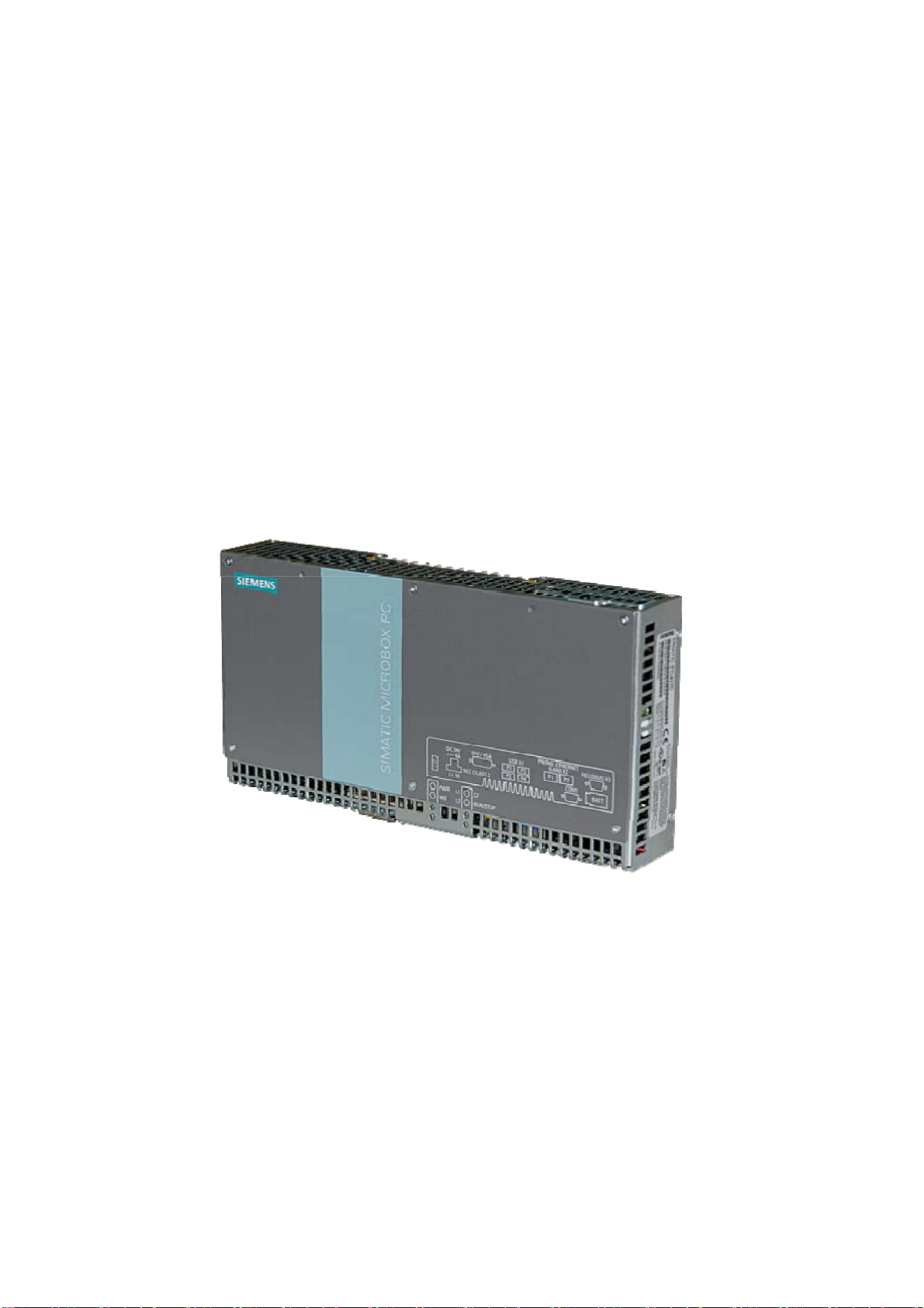
The SIMATIC IPC427C provides high-level industrial performance.
● Compact design
● Maintenance-free operation
● High degree of ruggedness
3
Figure 3-1 SIMATIC IPC427C
SIMATIC IPC427C
Operating Instructions, 04/2009, A5E02414743-01
11
Page 12

Description
3.2 Applications
3.2 Applications
The device provides industrial PC systems for high-performance and space-saving
applications in particular in the field of machine, systems and switchgear cabinet
engineering:
● Measuring and controlling of process and machine data (for example, automated washing
systems, assembling machines, packaging machines)
● Operating and visualization tasks with separate display / monitor solutions (information
terminals, large-scale displays in automotive production)
● Data logging and processing (for example, system data logging, distributed process
control)
SIMATIC IPC427C
12 Operating Instructions, 04/2009, A5E02414743-01
Page 13

Description
3.3 Features
3.3 Features
Basic data
Installation / mounting
Processor
Main memory
• Installation on a DIN rail
• Wall mounting
• Vertical mountin
• Hanging assembly
• Intel Celeron M 1.2 GHz, 800 MHz FSB, 1 MB SLC or
• Intel Pentium Core 2 Solo 1.2 GHz, 800 MHz FSB,
3 MB SLC or
• Intel Pentium Core 2 Duo 1.2 GHz, 800 MHz FSB,
3 MB SLC
• 512 MB DDR3-SDRAM SODIMM
• 1 GB DDR3-SDRAM SODIMM
• 2 GB DDR3-SDRAM SODIMM
• 4 GB DDR3-SDRAM SODIMM
Free slots for expansion Up to 3 x PCI/104 modules or 3x PC/104-
(PCI bus only);
installed with expansion frame
Graphics
Power supply 24 VDC (19.2 – 28.8 V) max. 4 A
Conditions of use
Drives and storage media
Compact Flash card
Hard disk ≥ 80 GB SATA HD 2.5" optional
SSD (Solid State Disk) ≥ 32 GB optional
Floppy/CDROM drive Connected via external USB port
USB stick Connected via external USB port
• Integrated Intel GMA4500 graphics
• CRT resolution of 640x480 pixels up to 1920x1200
pixels
• DVI resolution of 640x480 pixels up to 1920x1200
pixels
• 8-512 MB graphics memory taken from main memory
(dynamic UMA)
• Operation without fan
• 256 MByte optional or
• 2 GB optional or
• 4 GB optional or
• 8 GB optional
Plus
module
SIMATIC IPC427C
Operating Instructions, 04/2009, A5E02414743-01
13
Page 14

Description
3.3 Features
Basic data
Ports
Serial COM1 (RS232)
COM2 (RS232); optional
Graphics DVI-I: combined DVI and VGA
USB 4 x USB 2.0 high current
Ethernet 2 x RJ 45 (10/100/1000 Mbps)
PROFIBUS DP 12 Mbps (isolated potential,
compatible to CP 5611), optional
CAN interface Optional
Keyboard, mouse Connected via external USB port
Monitoring and safety functions
Temperature
• When permitted temperature range is exceeded
• Warnings can be analyzed by application program
(local, via LAN)
Watchdog
• Monitoring function for program execution
• Restart can be parameterized in the event of a fault
• Warnings can be analyzed by application program
(local, via LAN)
LED display 4 LEDs for displaying system status
2 of these can be programmed by the user1
Transient voltage interruption Up to 15 ms buffer time at full load
Buffer memory 2 MB battery-buffered SRAM1
Software
Operating systems
Available
• Without
• Windows Embedded Standard 2009
2
Project-specific
• Windows XP Professional MUI SP3 preinstalled
• LINUX
• QNX
• VxWorks
• Others on request
• RMOS3 V3.40 (ordered separately)
1
You can find additional information about addressing the LEDs or the SRAM under a
Windows operating system in the section "Output register LED L1/L2". You can find example
programs for addressing the LEDs under Windows XP and under RMOS3 under the FAQ at
the Customer Support site Industry Automation and Drive Technologies - Homepage
http://www.siemens.com/automation/service&support).
(
2
MUI: Multi Language User Interface; 5 languages (English, German, French, Spanish,
Italian)
SIMATIC IPC427C
14 Operating Instructions, 04/2009, A5E02414743-01
Page 15

Description
3.4 Windows Embedded Standard 2009
3.4 Windows Embedded Standard 2009
The supplied Windows Embedded Standard has the product version 2009. The overview
shows the basic device functions under Windows Embedded Standard 2009:
Function Hard disk / SSD version Compact Flash card version
Enhanced Write Filter (EWF) In RAM RAM(REG) In RAM RAM(REG)
SIMATIC IPC DiagBase Available V 1.2 Available V 1.2
Pagefile Deactivated in favor of the
EWF
System Restore Core Available Available
File based Writefilter (FBWF) Available Available
Registryfilter Available Available
Device Update Agent (DUA) Available Available
HORM Available Available
Telnet Server Available Available
Windows Backup Available Available
User Mode Driver Framework
(UMDF)
MUI GER/FRA/ITA/SPA
Administrator Account Available Available
User Account Available Available
Explorer Shell Available Available
Internet Explorer (IE) Available, IE7 Available, IE7
Internet Information Server (IIS) Available V 5.1 Available V 5.1
Terminal Services Available Available
Bluetooth Available Available
Wireless Network Support Available Available
Windows Firewall Available Available
Windows Security Center Available Available
MSN Explorer Available Not available
Outlook Express Available Available
Administrative Tools Available Available
SMS Advanced Client Available Not available
Remote Desktop Available V 6.0 Available V 6.0
Remote Assistance Available Available
.NET Framework Available, V3.5 Not available
ASP.NET Available, V3.5 Not available
Windows .NET Messenger Available V 4.7 Available V 4.7
Code pages/User
Location/Keyboard
Disk Management Services Available Available
Windows Installer Service Available V 3.1 Available V 3.1
Class Installer Available Available
Available Available
Default language: English
Available Selection available
Deactivated in favor of the EWF
GER
default language: English
SIMATIC IPC427C
Operating Instructions, 04/2009, A5E02414743-01
15
Page 16

Description
3.4 Windows Embedded Standard 2009
Function Hard disk / SSD version Compact Flash card version
CoDevice Installer Available Available
Windows Movie Maker Available V 2.1 Not available
Media Player Available, V11.0 Available, V11.0
Windows Media Player Tour Available Not available
DirectX V9.0c V9.0c
Accessories Available Available
Help files for all components Available Not available
Games Available Not available
Fonts 316 118
Windows XP Tour Available Not available
Microsoft Silverlight Available V 1.0 Available V 1.0
NetMeeting Available V 3.1 Available V 3.1
Note
Activation of "HORM" and creation of a "Hiber File"
When "HORM" is activated, the "Hibernate" function can be used for Windows Embedded
Standard 2009:
• EWFMGR C: /activatehorm
"Hibernate" is activated following a restart. The system then always boots from this file.
SIMATIC IPC427C
16 Operating Instructions, 04/2009, A5E02414743-01
Page 17
Description
3.5 Design
3.5 Design
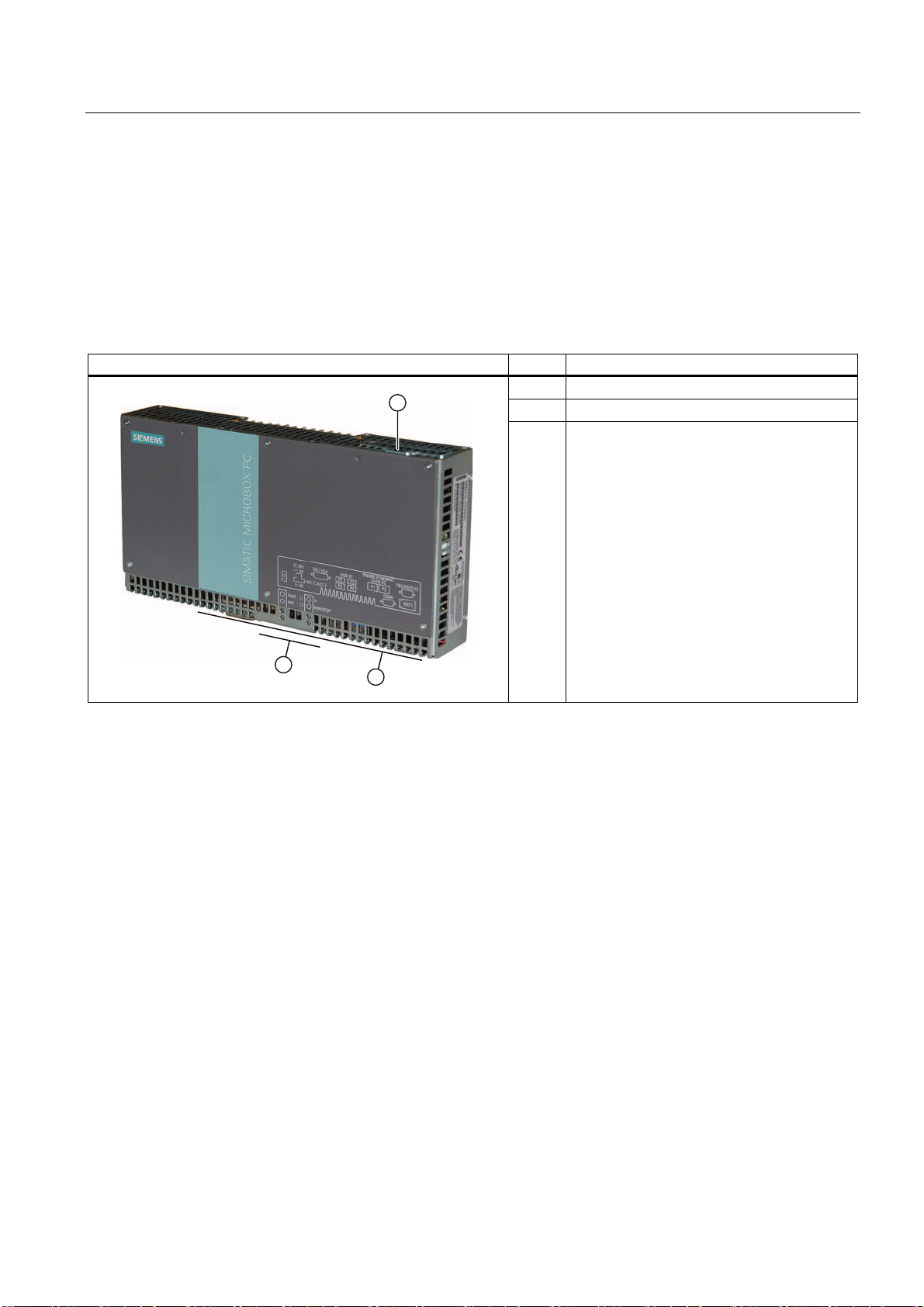
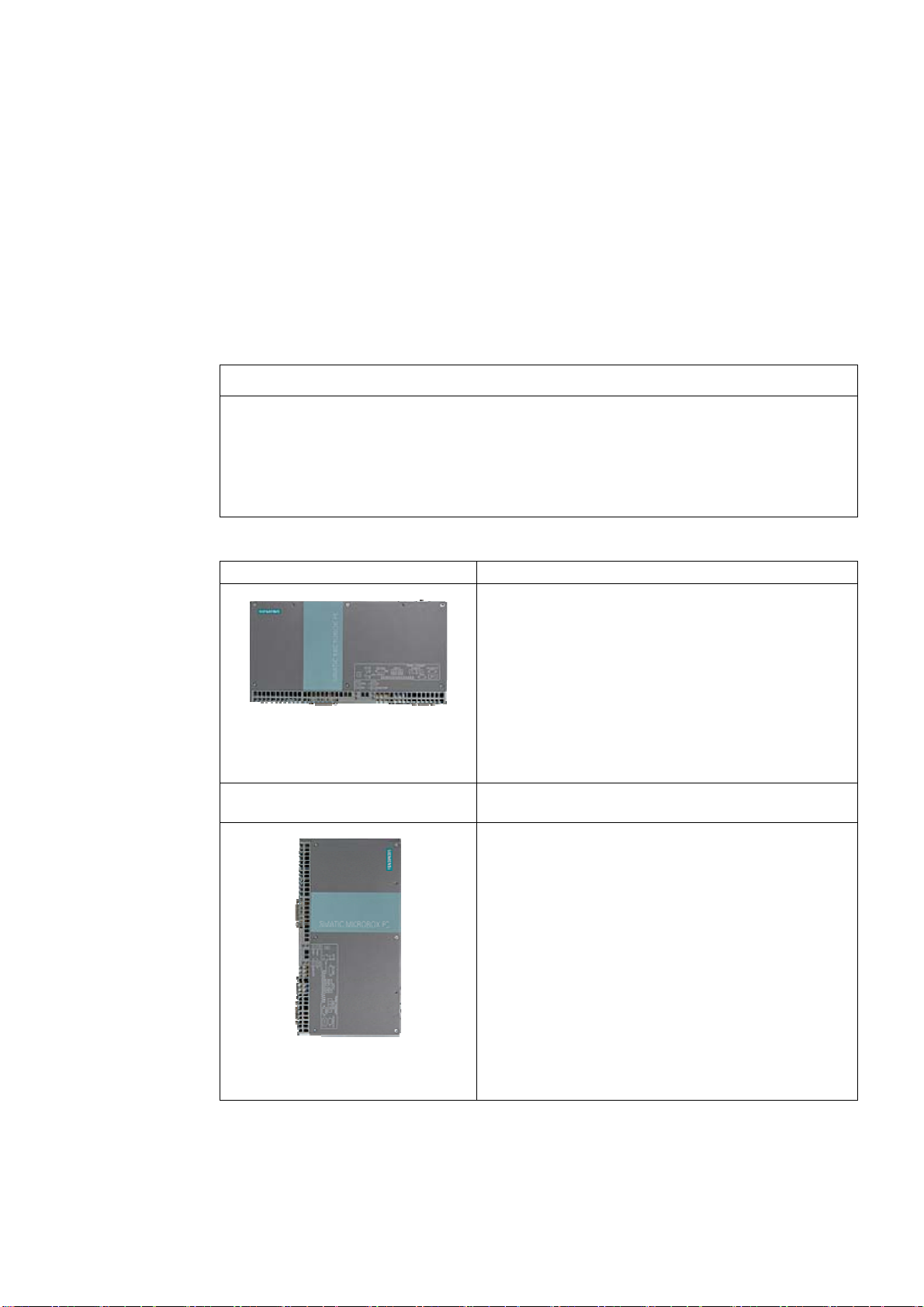
3.5.1 External Design
Device components Pos Description
① Cover plate for Compact Flash module
② Connection elements
③ Status displays
SIMATIC IPC427C
Operating Instructions, 04/2009, A5E02414743-01
17
Page 18
Description
3.5 Design
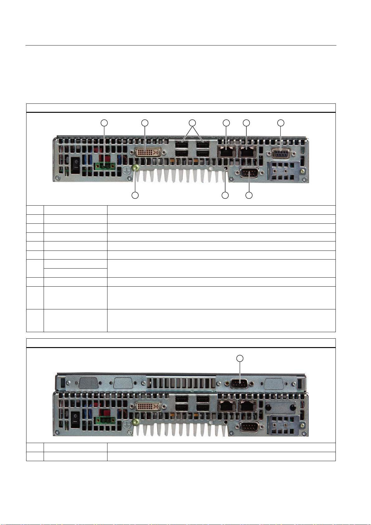
3.5.2 Connection components
Ports and power supply
Location of connection elements (version with PROFIBUS or CAN)
Pos Name Description
① 24 VDC Connection for a 24 V DC power supply
② DVI/VGA DVI/VGA connection for CRT or LCD monitor with DVI interface
③ USB 4 USB 2.0 connections, high-speed / low current
④ PN/IND. ETHERNET RJ45 Ethernet connection 1 (exclusive PCI interrupt) for 10/100/1000 Mbps
⑤ PN/IND. ETHERNET RJ45 Ethernet connection 2 (shared PCI interrupt) for 10/100/1000 Mbps
PROFIBUS DP/MPI ⑥
CAN fieldbus
⑦ COM1 Serial port (RS232) 9-pin Cannon connector
⑧ USB strain-relief
fastener
⑨ PE terminal The PE terminal (M4 thread) must be connected to the protective ground conductor of the
Location of the connection elements (second COM interface)
PROFIBUS DP/MPI interface (RS 485 isolated), 9-pin Cannon socket or CAN fieldbus
(on request)
The USB strain relief must be fastened to the device enclosure with an oval-head screw
(M4 thread). The USB cables can be fastened to the strain-relief assembly with a cable
tie.
plant, in which the device is to be installed. The minimum conductor cross-section may not
be less than 2,5 mm2.
Pos Designation Description
① COM2 Serial port (RS232) 9-pin Cannon connector
SIMATIC IPC427C
18 Operating Instructions, 04/2009, A5E02414743-01
Page 19
Description
3.5 Design
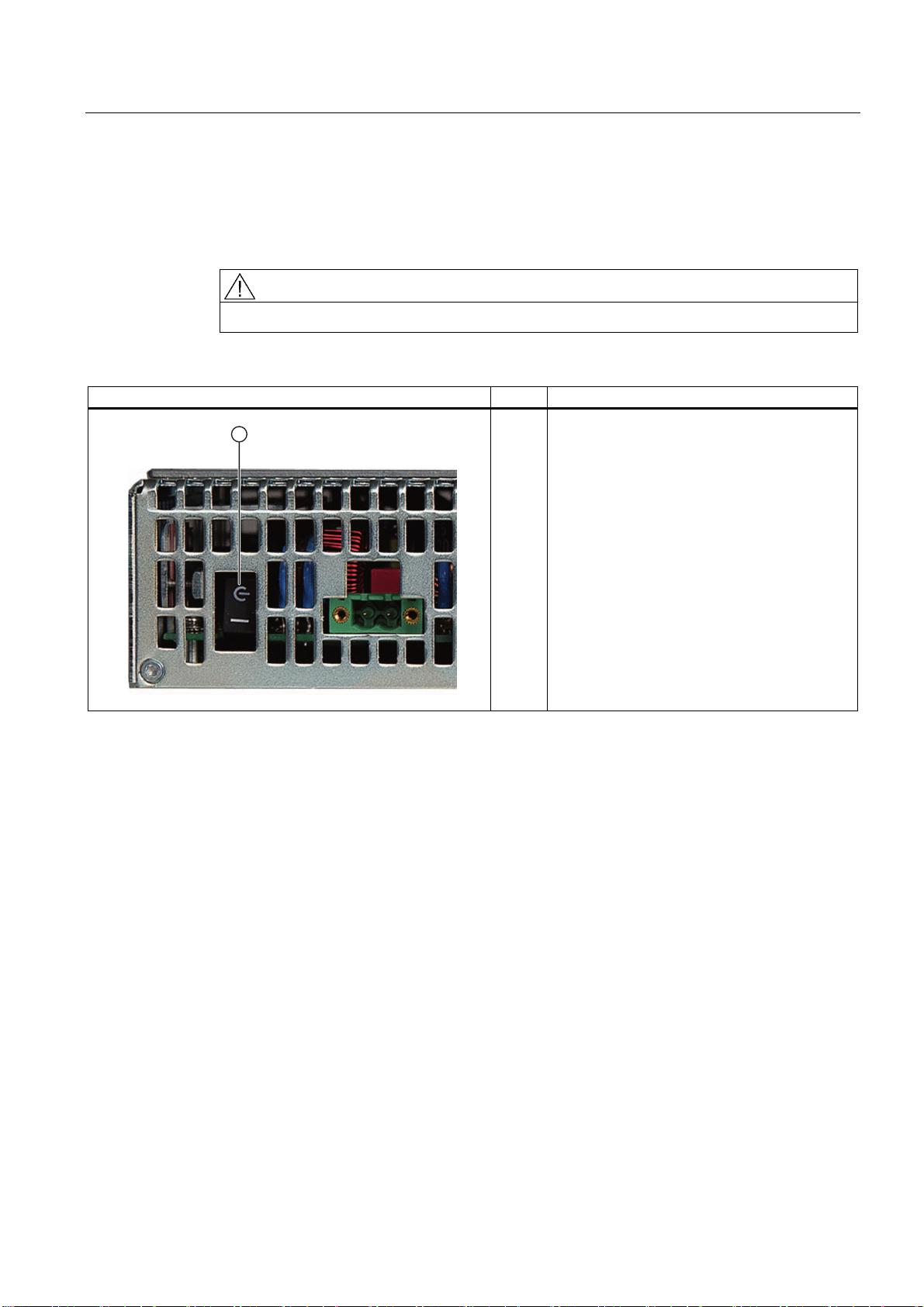
3.5.3 Operator controls
On/Off switch
CAUTION
The On/Off switch does not disconnect the device from the supply voltage.
Position of on/off switch Pos Description
① The on/off switch turns off the output voltages of
the power supply but not disconnect from the
supply system.
The delivery condition is: Power switch turned
off.
SIMATIC IPC427C
Operating Instructions, 04/2009, A5E02414743-01
19
Page 20
Description
3.5 Design
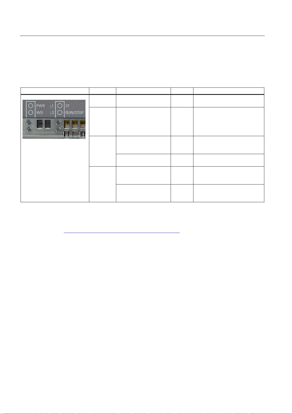
3.5.4 Status displays
Status displays LED Meaning LED Description
1
You can find additional information about addressing the LEDs or the SRAM under a
PWR Power supply OFF
WD Watchdog status display OFF
L1
SF
L2
RUN/STOP
User LED L1 OFF
Group errors RED Can be controlled by controller
User LED L2 OFF
RUN
STOP
GREEN
GREEN
RED
YELLOW
RED
YELLOW
GREEN
GREEN
YELLOW
Windows operating system in the section "Output register LED L1/L2". Example programs
for addressing the LEDs under Windows XP and under RMOS are available under the FAQ
at the Customer Support site Industry Automation and Drive Technologies - Homepage
http://www.siemens.com/automation/service&support).
(
Standby mode
Supply voltage available
Watchdog disabled Watchdog
enabled, monitoring time not
expired
Watchdog enabled, monitoring
time expired
Can be controlled by user
programs1
program (e.g. WinAC)
Can be controlled by user
programs1
Can be controlled by controller
program (e.g. WinAC)
1
1
SIMATIC IPC427C
20 Operating Instructions, 04/2009, A5E02414743-01
Page 21

Application planning
4.1 Transport
Despite the device's rugged design, its internal components are sensitive to severe
vibrations or shock. You must therefore protect the device from severe mechanical stress
when transporting it.
You should always use the original packaging for shipping and transporting the device.
CAUTION
Risk of damage to the device!
If you are transporting the device in extreme weather conditions with large fluctuations in
temperature, care must be take to ensure that no moisture forms on or in the device
(condensation).
If condensation has developed on the device, wait at least 12 hours before you switch it on.
4
SIMATIC IPC427C
Operating Instructions, 04/2009, A5E02414743-01
21
Page 22
Application planning
4.2 Unpacking and checking the delivery unit
4.2 Unpacking and checking the delivery unit
Unpacking the device
Note the following when unpacking the unit:
● It is advisable not to dispose of the original packing material. Keep it in case you have to
transport the unit again.
● Please keep the documentation in a safe place. It is required for initial commissioning and
is part of the device.
● Check the delivery unit for any visible transport damage.
● Verify that the shipment contains the complete unit and your separately ordered
accessories. Please inform your local dealer of any disagreements or transport damages.
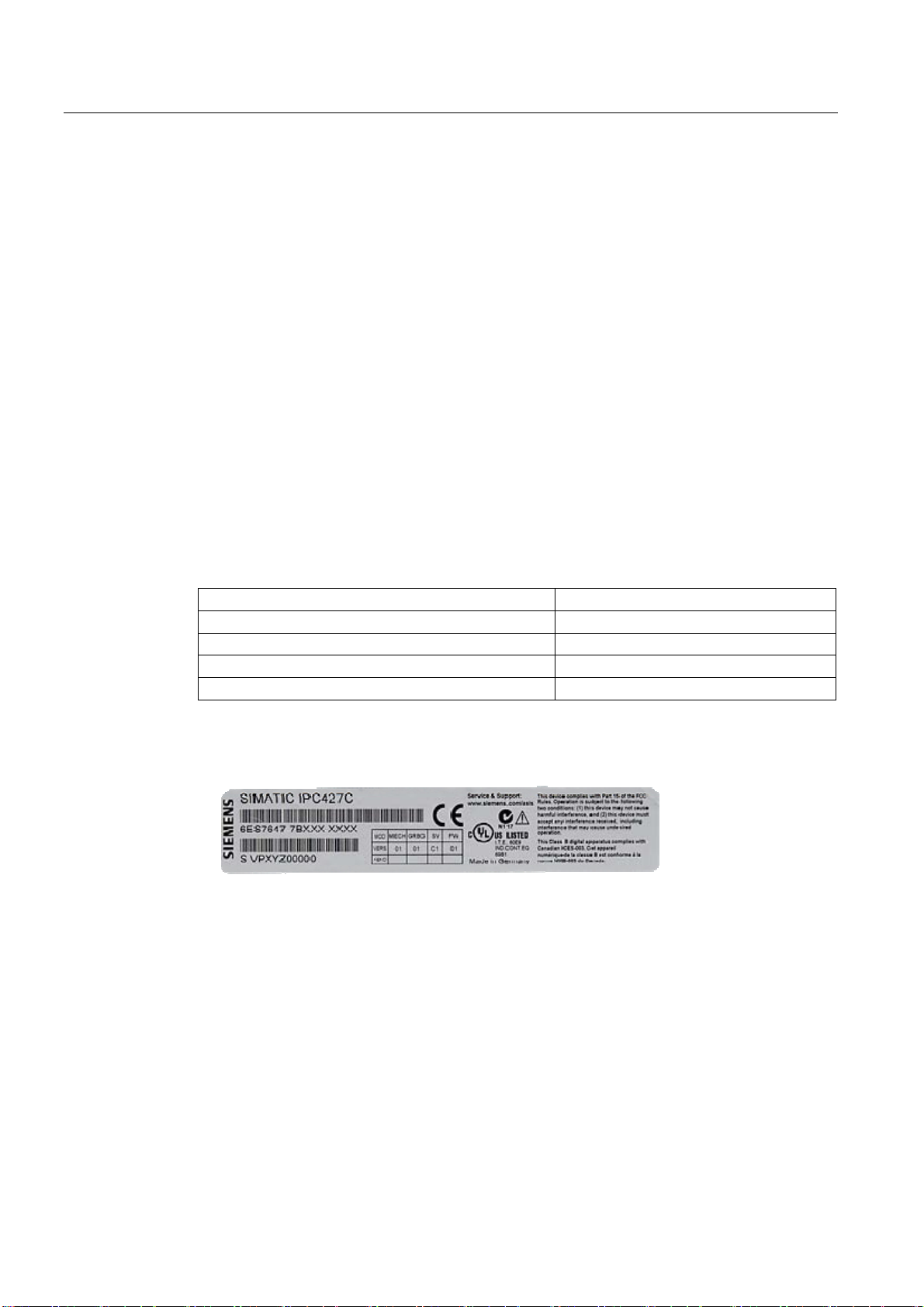
Noting the device identification data
The device can be identified uniquely with the help of these numbers in case of repairs or
theft.
Enter the data in the following table:
Serial number S VP ...
Order number of the device 6ES 7647-7B ...
Microsoft Windows Product Key
Ethernet address 1
Ethernet address 2
You can find the corresponding data here:
● Serial number: The serial number is available on the rating plate on the right side of the
device.
● Order number of the device: The order number is located on the rating plate.
SIMATIC IPC427C
22 Operating Instructions, 04/2009, A5E02414743-01
Page 23
Application planning
4.2 Unpacking and checking the delivery unit
● Ethernet address: The Ethernet address of the device is available in your BIOS Setup
(F2 function key) under Main > Hardware Options > Ethernet 1 Address or
Ethernet 2 Address.
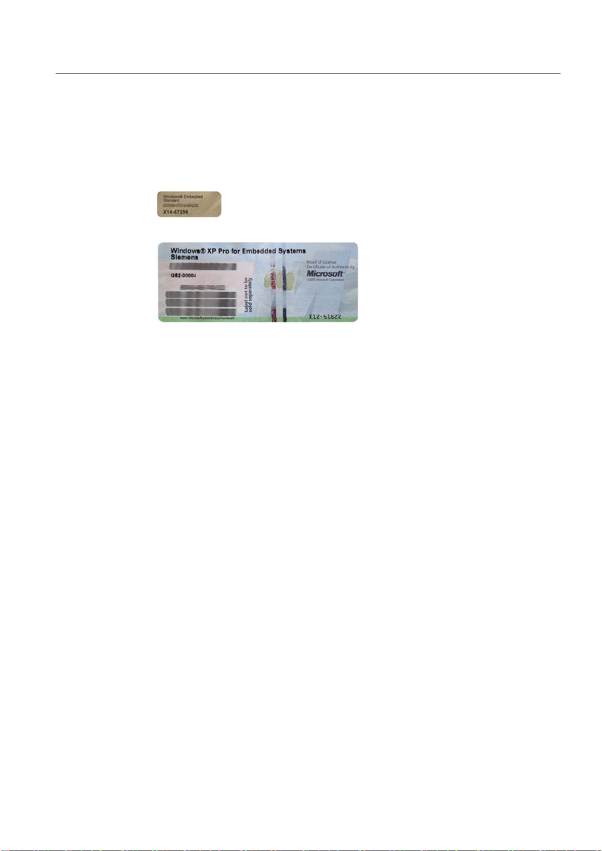
● Microsoft Windows "Product Key" from the "Certificate of Authenticity" (COA): The COA
label is only present in pre-installed Windows Embedded Standard 2009 or
XP Professional and is affixed to the back of the device.
Figure 4-1 COA Label Windows Embedded Standard 2009
Figure 4-2 COA Label Windows XP Pro for Embedded Systems
SIMATIC IPC427C
Operating Instructions, 04/2009, A5E02414743-01
23
Page 24

Application planning
4.3 Ambient and Environmental Conditions
4.3 Ambient and Environmental Conditions
When you plan your project, you should make allowances for:
● The climatic and mechanical environmental conditions specified in the specifications
given in your operating instructions.
● The device is approved for operation in closed rooms only.
● Avoid extreme ambient conditions. Protect the device against dust, moisture and heat.
● Do not place the device in direct sunlight.
● Ensure that the distance to other components or the sides of cabinets is at least 50 mm
above and 100 mm below the device.
● Do not cover the ventilation slots of the device.
● Always observe the mounting positions permitted for this device.
● The connected or built-in peripherals should not introduce a counter emf in excess of
0.5 V into the device.
SIMATIC IPC427C
24 Operating Instructions, 04/2009, A5E02414743-01
Page 25
Installing/mounting
5.1 Permitted mounting positions
NOTICE
The device is approved for operation in closed rooms only.
Ensure that there is a minimum clearance to the other components or the walls of a
housing:
• Below at least 100 mm
• Above at least 50 mm
Horizontal (preferred position) Permitted temperatures
5
Operation with hard disk:
• with up to 3 expansion modules
(max. load 9 W): +5 to +40°C
Operation with CompactFlash card and/or SSD drive:
• with up to 3 expansion modules
(max. load 9 W): 0 to +45°C
• with up to 3 expansion modules
(max. load 9 W) in RAL: 0 to +50°C
Operation with Compact Flash cards:
• without expansion modules in RAL: 0 to +55°C
Vertical
(power supply at the top)
SIMATIC IPC427C
Operating Instructions, 04/2009, A5E02414743-01
Operation with hard disk:
• with up to 3 expansion modules
(max. load 9 W): +5 to +40°C
With installed Compact Flash card:
• without expansion modules: 0 to +45°C
Operation with CompactFlash card and/or SSD drive:
• with up to 3 expansion modules
(max. load 9 W) in RAL: 0 to +45°C
Operation with Compact Flash cards:
• with up to 3 expansion modules
(max. load 9 W) in RAL: 0 to +50°C
Notes:
When mounted on a DIN rail, the device should be secured
to prevent shifting (e.g. with a DIN rail ground terminal).
25
Page 26
Installing/mounting
5.1 Permitted mounting positions
Suspended
Upright mounting Permitted temperatures
RAL = Restricted Access Location
(e.g. installation of the unit in a lockable cabinet)
Operation with CompactFlash card and/or SSD drive and
without expansion modules:
0 to +40°C
Note:
Mounting brackets are required if the device is suspended.
Operation with hard disk:
• with up to 3 expansion modules
(max. load 9 W): +5 to +40°C
With installed Compact Flash card:
• without expansion modules: 0 to +45°C
Operation with CompactFlash card and/or SSD drive:
• with up to 3 expansion modules
(max. load 9 W) in RAL: 0 to +45°C
Operation with Compact Flash cards:
• with up to 3 expansion modules
(max. load 9 W) in RAL: 0 to +50°C
NOTICE
The safety and installation instructions for the expansion modules should be followed if the
device is expanded with PCI-104 / PC/104-plus modules.
If necessary, the device should be installed in an enclosure that meets the requirements of
paragraphs 4.6 and 4.7.3 of IEC/UL/EN/DINEN60950-1.
SIMATIC IPC427C
26 Operating Instructions, 04/2009, A5E02414743-01
Page 27

Installing/mounting
5.2 Mounting information
5.2 Mounting information
Before you install the device, read the following mounting instructions.
NOTICE
Adhere to the SIMATIC assembly guidelines and the relevant DIN/VDE requirements or the
country-specific regulations when mounting in switching cabinets.
NOTICE
Ensure that the device is classified as "Open Type" when using the device in the area of
Industrial Control Equipment (UL508). A UL508 conform enclosure is therefore a
mandatory requirement for approval or operation according to UL508.
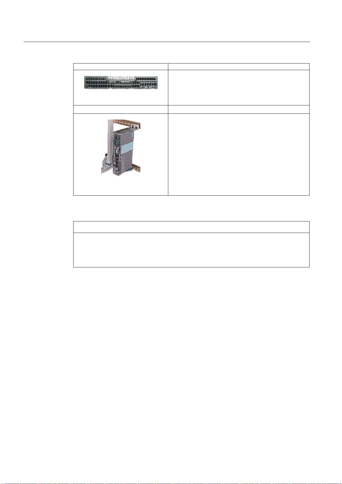
5.3 Mounting the device
Mounting methods
SIMATIC IPC427C can be mounted on DIN rails, with mounting brackets and in an upright
position.
SIMATIC IPC427C
Operating Instructions, 04/2009, A5E02414743-01
27
Page 28
Installing/mounting
5.4 Mounting on DIN rails
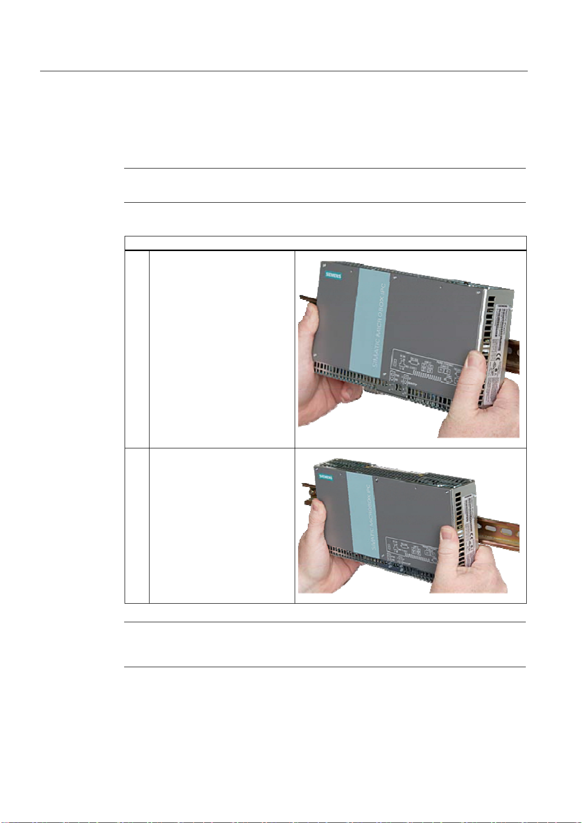
5.4 Mounting on DIN rails
Mounting the device on DIN rails
Note
Use of Siemens 35 mm standard mounting rail is recommended.
Steps for mounting on DIN rails
1. Set the device inclined on the
upper DIN rail.
2. Swing the device fully onto the rails
until both clamps completely latch.
Note
To ensure secure mounting on vertical mounting rails, a DIN rail ground terminal should be
mounted beneath the device.
SIMATIC IPC427C
28 Operating Instructions, 04/2009, A5E02414743-01
Page 29

Installing/mounting
5.4 Mounting on DIN rails
NOTICE
The rails are secured to a wall or cabinet similar to mounting with mounting brackets.
Ensure that the wall or ceiling can hold four times the total weight of the device (including
the rails and additional expansion modules). Also see section
brackets (Page
30).
Removing the device from the DIN rail
● Push down the device until the clamps release it.
● Swing the device out of the rails.
Mounting with mounting
SIMATIC IPC427C
Operating Instructions, 04/2009, A5E02414743-01
29
Page 30
Installing/mounting
5.5 Mounting with mounting brackets
5.5 Mounting with mounting brackets
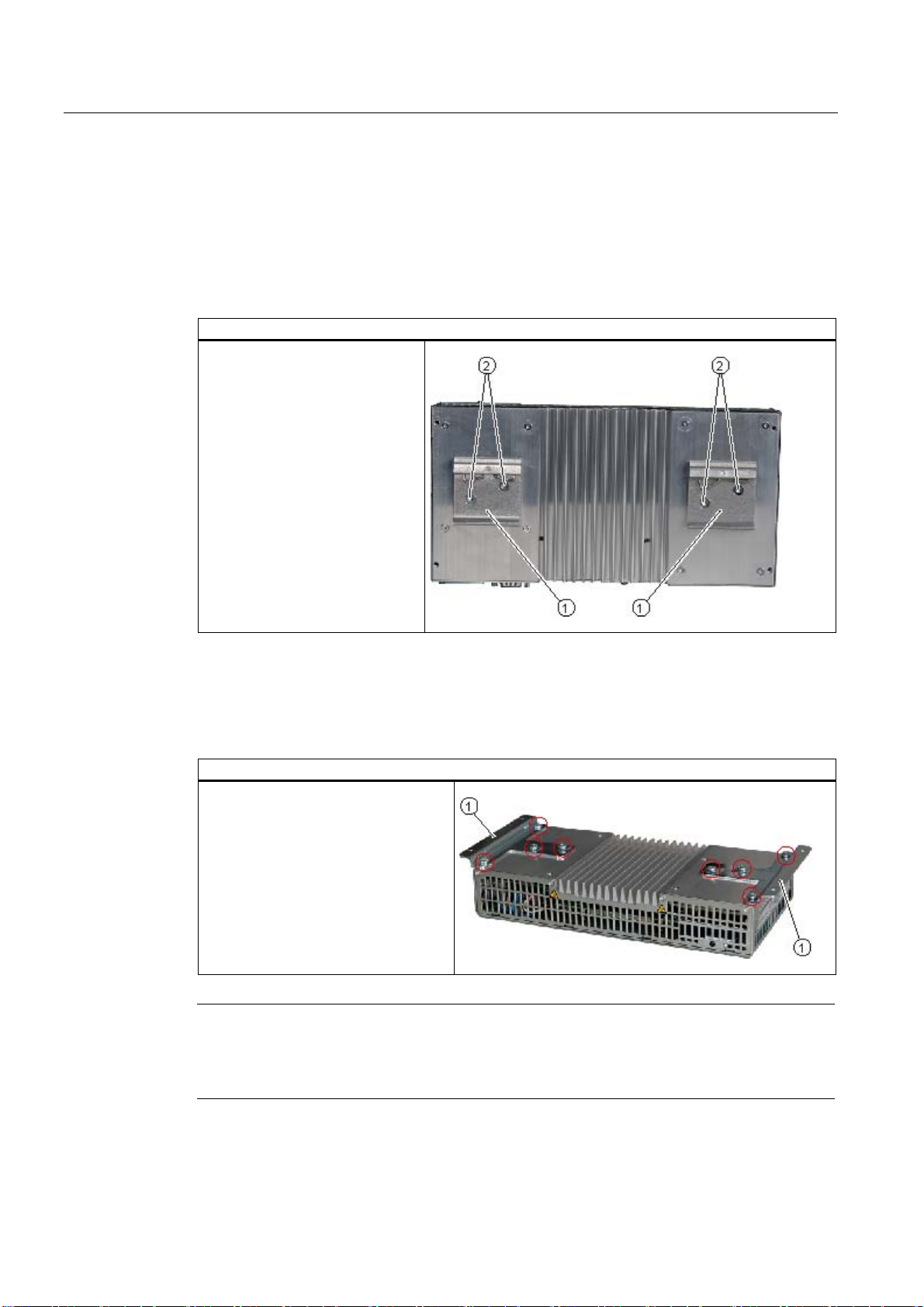
Removing mounting clamps from the device
Two mounting clamps are factory installed on the device for DIN rail mounting. These need
to be removed before mounting the mounting brackets.
Steps for removing the mounting clamps
Remove the four screws ② and
the two mounting clamps ① from
the back of the device.
Installing brackets on the device
Two mounting brackets are included in the device package. They can be installed on the
device with four screws supplied.
Steps for installing the mounting brackets
Install the mounting brackets on the
device.
Note
Required tools
You need a TORX T20 screwdriver to remove the mounting clamps and mount the mounting
brackets.
SIMATIC IPC427C
30 Operating Instructions, 04/2009, A5E02414743-01
Page 31

Installing/mounting
5.5 Mounting with mounting brackets
Mounting/demounting the device
The dimensions of the device with mounting brackets are listed under Dimension drawings of
the device with mounting brackets (Page
Mounting examples
Material Bore diameter Mounting
Concrete
Plasterboard
(min. 13 mm thick)
Metal
(min. 2 mm thick)
8 mm diameter
60 mm depth
14 mm diameter Gravity toggle: 4 mm diameter
5 mm diameter
99).
Dowel: 8 mm diameter
50 mm length
Screws: 4 mm diameter
50 mm length
50 mm length
Metal screws M 4: 4 mm diameter
15 mm length
WARNING
Ensure that the wall or ceiling can hold four times the total weight of the device (including
the cabinet brackets and additional expansion modules).
SIMATIC IPC427C
Operating Instructions, 04/2009, A5E02414743-01
31
Page 32

Installing/mounting
5.6 Upright mounting
5.6 Upright mounting
With the available optional vertical mounting kit you have the possibility to implement a place
saving installation.
Mounting the vertical mounting bracket onto the device
① Device ② Screws ③ Vertical mounting bracket
Note
• Information on installation and operation is available in the supplement of the
accessories.
SIMATIC IPC427C
32 Operating Instructions, 04/2009, A5E02414743-01
Page 33

Connecting
6.1 Connecting peripheral equipment
NOTICE
Connect only peripheral devices approved for industrial applications conforming to
EN 61000-6-2 / IEC 61000-6-2.
Note
Hot-plug peripherals (USB) may be connected while the PC is in operation.
CAUTION
Peripheral devices that are incapable of hot-plugging may only be connected after the
device has been disconnected from the power supply.
6
CAUTION
Strictly adhere to the specifications for peripheral equipment.
Note
A DVI or CRT monitor should be connected and switched on when the device boots in order
for it to be correctly detected by the BIOS and the operating system. The screen may
otherwise remain dark.
NOTICE
The connected or built-in peripherals, such as USB drives, should not introduce a counter
emf into the device.
A counter emf greater than 0.5 V to ground on the + 3.3 VDC / + 5 VDC / + 12 VDC power
rail due to a connected or integrated component can prevent normal operation or even
destroy components of the device.
SIMATIC IPC427C
Operating Instructions, 04/2009, A5E02414743-01
33
Page 34

Connecting
6.2 Connecting the 24 V DC power supply
6.2 Connecting the 24 V DC power supply
To be noted before you connect the device
Note the following in order to operate the device safely and according to regulation:
Connecting
WARNING
The device should only be connected to a 24V DC power supply which satisfies the
requirements of safe extra low voltage (SELV).
If the device is used on a wall, in an open rack or other similar locations, an NEC Class 2
current source is required in order to meet the UL requirements (UL 60950-1). In all other
cases (IEC / EN / DIN EN 609501) either a current source of limited output (LPS = Low
Power Source), or a line-side fuse or a line-side circuit breaker is necessary. The power
needs to be limited to a value below 4.16 A. The fuse value required: Max. 4 A.
Use the special plug supplied to connect the supply voltage. Connect the PE conductors as
described in the next section.
NOTICE
The permitted cable cross-section for the 24 VDC connection is 0.75 mm
2
to 2.5 mm2.
NOTICE
If a CompactFlash card is used in the device, make sure that the card is seated correctly
before you connect it.
Steps for connecting the device to the 24 V DC power supply
1. Switch off the 24 V DC power source.
2. Connect the power supply using the plug
(included in the package).
3. Connect the PE conductor.
3LQ
0LQ
SIMATIC IPC427C
34 Operating Instructions, 04/2009, A5E02414743-01
Page 35

Connecting
6.3 Protective ground connection
6.3 Protective ground connection
The PE terminal (M4 thread) on the device (large surface, large-area contact) must be
connected to the PE conductor on the cabinet or system in which the PC is to be installed.
The conductor cross-section must not be less than 2.5 mm
The PE terminal is needed to protect the device and ensures that interference signals
generated by external power cables, signal cables or cables to the I/O modules are safely
discharged to earth.
Required tool for protective earth terminal: TORX T20 screwdriver
Protective earth terminal
Connect the PE terminal (M4 thread)
① on the device to the PE conductor
on the cabinet or system in which the
PC will be installed. The minimum
conductor cross-section may not be
less than 2,5 mm
2
.
2
.
SIMATIC IPC427C
Operating Instructions, 04/2009, A5E02414743-01
35
Page 36

Connecting
6.4 USB strain-relief
6.4 USB strain-relief
The USB strain-relief provided as an accessory is used to prevent accidental loosening of
the USB cable from the device. A cable binder (not included in the package) is needed to
use this accessory.
To fix the USB strain relief, you will need a TORX T20 screwdriver.
Steps for connecting the USB strain-relief
1. Fasten the USB strain-relief ① to the
device housing with an oval-head
screw (M4 thread).
2. Thread the cable tie ② through the
comb of the USB strain-relief to
clamp the USB cable.
SIMATIC IPC427C
36 Operating Instructions, 04/2009, A5E02414743-01
Page 37

Commissioning
7.1 Note before commissioning
Factory state
The SIMATIC IPC427C is available in the following versions:
● With the Windows Embedded Standard 2009 operating system (pre-installed on
CompactFlash card, SSD drive or the hard disk)
● With the Windows XP Professional operating system (pre-installed on SSD drive or the
hard disk)
● Without operating system
Connections before commissioning
Before connecting the device to the power supply, a DVI or CRT monitor should be
connected in order for it to be correctly detected by the BIOS and the operating system
during startup.
7
CAUTION
Risk of damage to the device
If condensation has developed, wait at least 12 hours before commissioning the device.
NOTICE
Windows Embedded Standard 2009: Read the EWF and FBWF information
Two configurable write filters (Enhanced Write Filter and File Based Write Filter) are
provided with Windows Embedded Standard 2009. Please be aware of this when activating
and using the EWF/FBWF information, otherwise you may experience data loss.
Note
Setting up CompactFlash cards on the employed device
If you want to use CompactFlash cards with the device, they need to be set up on the
device. CompactFlash cards set up on other devices will not boot due to the differing drive
parameters.
SIMATIC IPC427C
Operating Instructions, 04/2009, A5E02414743-01
37
Page 38

Commissioning
7.2 Commissioning - Windows Embedded Standard 2009
7.2 Commissioning - Windows Embedded Standard 2009
7.2.1 Basic commissioning - initial startup
Requirements
● The device is connected to the 24 VDC power supply.
● Equipotential bonding is connected.
● The cables are correctly plugged in.
Configuring the operating system
When the computer is started with the power switch for the first time, the
Windows Embedded Standard 2009 operating system on the Compact Flash card or hard
disk is configured automatically.
Proceed as follows:
1. Switch the device on using the On/Off switch. The PC performs a self-test (POST).
During the self-test, this message appears:
Press F2 go to Setup Utility or
Press ESC go to Boot Manager
2. Wait until this message is cleared, then follow the instructions on the screen.
NOTICE
The device may not be switched off at any time during the installation process.
Do not change the default BIOS settings, otherwise the operating system setup may
become corrupted.
3. Restart
After you have entered all the necessary information and the operating system is
configured, you are prompted to restart the system. Respond to this prompt with Yes.
Note
System startup can take considerably longer than usual for the initial commissioning.
Only a blue or black screen is displayed for several minutes.
When you switch on the PC now, the logon window or the user interface of the
Windows Embedded Standard 2009 operating system is automatically opened when the
startup routine is completed.
Note
To prevent data loss, it is advisable to create an image of your system partition after initial
commissioning.
SIMATIC IPC427C
38 Operating Instructions, 04/2009, A5E02414743-01
Page 39

Commissioning
7.2 Commissioning - Windows Embedded Standard 2009
Switch off the device
When you work with Windows Embedded Standard , always shut down the PC with the
command Start > Shut Down.
Note
The Enhanced Write Filter should be enabled following the installation of Windows
Embedded Standard on a CompactFlash card or SSD drive. When this is enabled, the
device can be switched off with the power switch by disconnecting the power supply.
SIMATIC IPC427C
Operating Instructions, 04/2009, A5E02414743-01
39
Page 40

Commissioning
7.3 Commissioning - Windows XP Professional
7.3 Commissioning - Windows XP Professional
7.3.1 Basic commissioning - initial startup
Requirements
● The device is connected to the 24 VDC power supply.
● Equipotential bonding is connected.
● The cables are correctly plugged in.
Configuring the operating system
When the computer is started with the power switch for the first time, the Windows XP
Professional operating system on the hard disk or SSD drive is configured automatically.
Proceed as follows:
1. Switch the device on using the On/Off switch. The PC performs a self-test (POST).
During the self-test, this message appears:
Press F2 go to Setup Utility or
Press ESC go to Boot Manager
2. Wait until this message is cleared, then follow the instructions on the screen.
NOTICE
The device may not be switched off at any time during the installation process.
Do not change the default BIOS settings, otherwise the operating system setup may
become corrupted.
3. Automatic restart
After you have entered all necessary information and the operating system is configured,
the PC is automatically restarted and displays the user interface of the operating system.
Note
System startup can take considerably longer than usual for the initial commissioning.
When you switch on the PC now, the user interface of the Windows XP Professional
operating system is automatically opened when the startup routine is completed.
Note
To prevent data loss, it is advisable to create an image of your system partition after initial
commissioning.
SIMATIC IPC427C
40 Operating Instructions, 04/2009, A5E02414743-01
Page 41

Commissioning
7.3 Commissioning - Windows XP Professional
Switch off the device
When you work with Windows XP Professional, always shut down the PC with the command
Start > Shut Down. You can then switch off the device with the power switch or by
disconnecting the power supply.
7.3.2 Setting up the language selection for Windows XP Professional / Embedded Standard
The Multilanguage User Interface (MUI) allows you to set up the Windows XP Professional /
Embedded Standard menus and dialogs for additional languages.
Default language of your Windows XP MUI installation is English and a US keyboard layout.
You can change the language in the Control Panel. Select:
Start > Control Panel > Regional and Language Options
Languages, tab Language used in menus and dialogs
field.
For the Regional and Language Options set the default as non-Unicode programs under Advanced in
addition to the language for menus and dialogs.
SIMATIC IPC427C
Operating Instructions, 04/2009, A5E02414743-01
41
Page 42

Commissioning
7.4 Commissioning - other operating systems
7.4 Commissioning - other operating systems
7.4.1 Commissioning - guide
The desired operating system can be installed on the hard disk, CompactFlash card or SSD
drive. A variety of USB devices (hard disk, external floppy or CD-ROM drive, USB stick) or
Compact Flash cards can be used as boot media.
&RPPLVVLRQLQJ
6,0$7,&,3&&
The following provides an overview of the steps involved in commissioning:
Steps Description
1 Select and create a boot
2 Install the operating system
3 Select final boot medium In the BIOS Setup, select the medium on which the operating
Additional information
Further information about installation and commissioning is available in the documentation of
the respective operating system.
6HOHFWLQJFUHDWLQJ
WKHERRWPHGLXP
IRULQVWDOODWLRQ
medium for installation.
on the boot medium.
,QVWDOOLQJWKH
RSHUDWLQJV\VWHP
6HOHFWLQJWKHDFWLYH
ERRWPHGLXP
IURPWKHERRWPHGLXP
Select a suitable boot medium for the operating system to be
used in the BIOS Setup (CD-ROM drive, Compact Flash card,
hard disk or USB device). See Boot menu (Page 126).
If no boot medium is available, one must be created based on
the instructions provided by the respective operating system
documentation.
For example, you can use the SIMATIC PC/PG Image Creator
tool to make a USB stick a bootable medium.
Install the operating system based on the instructions provided
by the respective documentation.
system has been installed.
SIMATIC IPC427C
42 Operating Instructions, 04/2009, A5E02414743-01
Page 43

Integration into an Automation System
8.1 Overview
Options of integration in existing or planned system environments/networks:
Ethernet
The integrated Ethernet port (10/100/1000 Mbps) can also be used for communication and
for data exchange with automation devices such as SIMATIC S7.
For this purpose you require the "SIMATIC NET" software package.
PROFIBUS/MPI
The optional electrically isolated PROFIBUS interface (12 Mbps) can be used to interconnect
distributed field devices or for coupling to SIMATIC S7.
The "SOFTNET for PROFIBUS" software package is required for coupling to S7 automation
systems.
8
CAN
CAN interface for connection to CAN field systems (on request).
RS232
The serial port can be used for data communication (via terminal applications, for example).
Additional information
Additional information is available in the catalog and the online ordering system Industrial
Automation and Drive Technologies (
http://mall.automation.siemens.com).
SIMATIC IPC427C
Operating Instructions, 04/2009, A5E02414743-01
43
Page 44

Integration into an Automation System
8.1 Overview
SIMATIC IPC427C
44 Operating Instructions, 04/2009, A5E02414743-01
Page 45

Functions
9.1 Monitoring Functions
9.1.1 Introduction
Even in its basic version, the device comes with optional monitoring functions. When used in
combination with the appropriate software, the following functions for displaying, monitoring
and controlling are available:
● Temperature monitoring (over / under temperature)
● Monitoring of the battery level
● Monitoring of hard disks, CompactFlash cards and SSD drives with S.M.A.R.T.
functionality
● Watchdog (hardware or software reset of the computer)
● Operating hours meter (information on the cumulative run time)
9
SIMATIC PC DiagBase software
With the SIMATIC PC DiagBase software (included in product package), you can use these
functions for local monitoring. You can use the DiagBase Management Explorer application
for general monitoring or DiagBase Alarm Manager for notification of individual alarms.
Additional information on the functions of the SIMATIC PC DiagBase software is available in
the online help.
SIMATIC PC DiagMonitor software
SIMATIC PC DiagMonitor software is provided on CD (not included in the scope of delivery).
It contains the monitoring software, the software for the stations to be monitored and a library
for creating custom applications.
SIMATIC IPC427C
Operating Instructions, 04/2009, A5E02414743-01
45
Page 46

Functions
9.1 Monitoring Functions
9.1.2 Temperature monitoring/display
Temperature monitoring
The temperature is recorded by means of three thermocouples. The sensors monitor the
processor temperature, the temperature near the RAM module and the motherboard around
the DVI/VGA socket.
If one of the three configured temperature values is exceeded (CPU: 100°C, RAM: 95°C,
motherboard: 95°C), the following fault reaction is triggered:
Reaction Option
The DiagBase or DiagMonitor software is enabled None
The temperature error is retained in memory until temperatures have fallen below the
thresholds and it is reset by one of the following measures:
● Acknowledgment of the error message by the monitoring software
● Restart of the device
SIMATIC IPC427C
46 Operating Instructions, 04/2009, A5E02414743-01
Page 47

Functions
9.1 Monitoring Functions
9.1.3 Watchdog (WD)
Function
If the user program does not respond to the watchdog within the predetermined monitoring
time, the watchdog monitors the program process and informs the user about various
reactions.
After POWER ON of the device or after a HW RESET (cold restart), the watchdog is in idle
state, i.e. a reaction of the WD will not be triggered and the Watchdog LED is switched off.
Watchdog reactions
If the watchdog is not triggered again within the set time, the following reactions will be
triggered:
Reaction Option
Switch watchdog LED to red None
Trigger a PC reset Configurable
Enabling the DiagBase or DiagMonitor software None
Note
If the desired device reset is not performed, go the Advanced menu of the BIOS Setup and
set the SafeCard functions to Enabled. Contact Customer Support for a detailed description
of the Watchdog functions.
WD monitoring times
The monitoring times are defined as follows:
Normal mode: 94 ms, 210 ms, 340 ms, 460 ms, 590 ms, 710 ms, 840 ms and 960 ms.
Macro mode: 2s, 4s, 6s, 8s, 16s, 32s, 48s and 64s.
Note
The watchdog is retriggered if the monitoring time is changed at the active watchdog (that is
while the watchdog is running)!
SIMATIC IPC427C
Operating Instructions, 04/2009, A5E02414743-01
47
Page 48

Functions
9.2 Enhanced Write Filter (EWF)
9.2 Enhanced Write Filter (EWF)
Purpose and function
The EWF (Enhanced Write Filter) is a function that is only available with Windows
Embedded operating systems. It provides write protection that can be configured by the
user.
The Enhanced Write Filter allows you to boot Windows Embedded Standard 2009 from
write-protected media (such as CD-ROM), to write protect individual partitions and adapt the
performance of the file system to your needs (when using CompactFlash cards, for
example).
EWF can be used to minimize write access to Compact Flash cards. This is important
because the write cycles on Compact Flash cards are limited due to technical reasons. We
therefore recommend using EWF if you work with Compact Flash cards.
Set EWF
CAUTION
Activate only one write filter per partition - otherwise you may incur data loss.
Both EWF and FBWF are preinstalled in the SIMATIC IPC images.
Ensure that only one write filter is enabled on a partition, otherwise you may incur data loss.
Note
The Enhanced Write Filter is disabled by default for Windows Embedded Standard 2009.
After the operating system has been set up, you should back up your date and then enable
the EWF.
The EWFMGR.EXE program can be used to install, enable or disable the EWF. Use the
command prompt to call up the program. The following functions are available:
Function Command
Write-protect drive C: Switching on
Write-protect drive C: disable
(modified files are accepted)
Modified files on drive C: Accept
Display information about the EWF drive
Display help
ewfmgr c: -enable
ewfmgr c: -commitanddisable
ewfmgr c: -commit
ewfmgr c:
ewfmgr c: /h
Note
The EWF commands affecting the write protection do not become active until after the next
booting process.
SIMATIC IPC427C
48 Operating Instructions, 04/2009, A5E02414743-01
Page 49

Functions
9.2 Enhanced Write Filter (EWF)
Special features for the use of Enhanced Write Filters (EWF)
● In the event of a power failure, if the EWF is enabled changes made after the boot
sequence on drive C: are lost.
To prevent data loss in the event of a power failure, the use of a USV is recommended.
● You can save the files in the EWF RAM overlay to the Compact Flash card or the hard
disk before you shut down the device. To do so, enter the following command in the
command prompt:
ewfmgr c: -commitanddisable
Then restart the system.
ewfmgr c: -enable
Then restart the system.
Note
When the system is set to automatically adjust the clock for daylight saving time adjustment,
systems without central time management and with activated EWF set the clock forward or
backward by one hour in the daylight saving time or standard time period each time the
system boots.
The reason for this behavior is that Windows Embedded Standard 2009 has a registry entry
that detects if the clock has been adjusted for daylight saving time. Since this file is also
protected against modification by the EWF, the marker is lost during the boot sequence and
the adjustment is made again.
We therefore recommend that you deactivate the automatic adjustment and change the
clock manually.
Procedure:
1. Switch off the EWF filter (ewfmgr c: -commitanddisable) and reboot the system.
2. Deactivate automatic adjustment in the Control Panel. In the Time Zone tab opened with
the menu command Start > Control Panel > Date and Time, remove the check mark from
the "Automatically adjust clock for daylight saving changes" check box.
3. Enable EWF again (ewfmgr c: -enable) and reboot the system.
SIMATIC IPC427C
Operating Instructions, 04/2009, A5E02414743-01
49
Page 50

Functions
9.3 File Based Write Filter (FBWF)
9.3 File Based Write Filter (FBWF)
Purpose and function
With the Feature Pack 2007 for Windows XP Embedded, Microsoft introduced a second
write filter, File Based Write Filter (FBWF).
In contrast to EWF, which protects partitions based on sectors, FBWF works on the file level.
When FBWF is enabled, all files and folders of a partition are protected unless they are
included in an exception list.
FBWF is disabled by factory default in the operating system images for SIMATIC IPC and
must be enabled and configured by the user.
When you enable FBWF, the folders C:\FBWF and D:\FBWF are authorized for writing by
default.
Comparison between EWF and FBWF
● You should prefer FBWF, because it is more flexible in its configuration and allows
immediate writing without rebooting.
● If you use HORM or compressed NTFS, EWF is indispensable.
Configuring FBWF
FBWF can be configured in command console using the program FBWFMGR.EXE.
CAUTION
Activate only one write filter per partition - otherwise you may incur data loss.
Both EWF and FBWF are preinstalled in the SIMATIC IPC images.
Ensure that only one write filter is enabled on a partition, otherwise you may incur data
loss.
NOTICE
• Observe the following syntax: Enter a space after the drive designation colon.
• Changes for direct write access only take effect after rebooting.
• Only existing files and folders can be entered in the exception list.
SIMATIC IPC427C
50 Operating Instructions, 04/2009, A5E02414743-01
Page 51

Functions
9.3 File Based Write Filter (FBWF)
Function Command
Display the current FBWF status
Enable FBWF after the next startup
Write to protected files
Adding/removing elements in the exception list:
• Add file
• Add folder
• Remove file
• Remove folder
Call up the help function
fbwfmgr /displayconfig
fbwfmgr /enable
fbwfmgr /commit c: \Test.txt
fbwfmgr /addexclusion
C: \Test.txt
fbwfmgr /addexclusion C: \Test
folder
fbwfmgr /removeexclusion
C: \Test.txt
fbwfmgr /removeexclusion
C: \Test folder
fbwfmgr /?
For detailed instructions on FBWF go to (http://msdn.microsoft.com/en-
us/library/aa940926(WinEmbedded.5).aspx)
SIMATIC IPC427C
Operating Instructions, 04/2009, A5E02414743-01
51
Page 52

Functions
9.4 SRAM buffer memory
9.4 SRAM buffer memory
For applications to be able to store data following a power failure, the motherboard features
a battery-buffered CMOS-RAM. If the supply voltage fails longer than 5 ms, this is indicated
by the DC FAIL signal.
Enough time is provided for copying data to the buffered RAM that 256 KB can be saved
with a full configuration.
A maximum 2048 Kb memory window is displayed via a PCI address register. The base
address is initialized by the BIOS.
A corresponding function is implemented there for using the CMOS-RAM under WinAC RTX.
NOTICE
If replacement of the battery takes longer than 30 seconds, the data saved in the CMOS
RAM and in the buffered SRAM is lost.
SIMATIC IPC427C
52 Operating Instructions, 04/2009, A5E02414743-01
Page 53

Functions
9.5 Battery monitoring
9.5 Battery monitoring
The installed buffer battery has a service life of at least 5 years. The status can be checked
with two-tier battery monitoring. The information can be read from an I/O register and
evaluated.
When the first warning level is reached, the remaining service life of the battery for buffering
CMOS data and buffered SRAM is at least 1 month.
SIMATIC IPC427C
Operating Instructions, 04/2009, A5E02414743-01
53
Page 54

Functions
9.6 Operation without monitor and keyboard
9.6 Operation without monitor and keyboard
The device can be operated without a monitor and keyboard. The device startup is
guaranteed without these peripherals. A USB keyboard and mouse and an analog CRT
monitor can be later connected for diagnostics.
A digital DVI monitor can only be subsequently activated when the Windows Embedded
Standard 2009 or Windows XP Professional operating system has fully booted.
SIMATIC IPC427C
54 Operating Instructions, 04/2009, A5E02414743-01
Page 55

Expansions and Configurations
10.1 Open the device (front panel)
CAUTION
Work on the open device may only be carried out by authorized and qualified personnel.
Within the warranty time, you are only allowed to install expansions for memory and
expansion card modules.
CAUTION
The device contains electronic components which may be destroyed by electrostatic
charge.
You therefore need to take precautionary measures before you open the device. Refer to
the ESD guidelines on handling electrostatically sensitive components under
Guidelines (Page
147).
10
ESD
Tools
Preparation
● Cover and top cover plate: Torx T8
● Hard disk mounting: Torx T10
● Protective earth terminal: Torx T20
● Spacing bolts PC/104: Hexagon head 5mm
Isolate the device from power supply.
SIMATIC IPC427C
Operating Instructions, 04/2009, A5E02414743-01
55
Page 56

Expansions and Configurations
10.1 Open the device (front panel)
Open the device
Steps in opening the device (front panel)
1 Remove the six screws.
2 Remove the front panel.
SIMATIC IPC427C
56 Operating Instructions, 04/2009, A5E02414743-01
Page 57

Expansions and Configurations
10.2 Memory expansion
10.2 Memory expansion
10.2.1 Installing the memory module
Memory expansion options
The motherboard is equipped with one slot for an SO-DIMM DDR3 memory module. This
lets you expand the memory capacity of your device to a maximum of 4 GB. 3 GB of this
memory is available for the operating system and applications.
Note
We recommend using the original spare parts for memory configuration.
Preparation
Disconnect the device from the power supply.
CAUTION
The electronic components on the PCBs are highly sensitive to electrostatic discharge.
Always take appropriate precautionary measures when handling these components. Refer
to the ESD directives on handling electrostatically sensitive components
147).
(Page
Removing a memory module
How to remove a memory module
1 Open the device.
2 Open the retention clamps ①. Tilt the
memory module forward.
ESD Guidelines
3 Carefully remove the memory module.
SIMATIC IPC427C
Operating Instructions, 04/2009, A5E02414743-01
57
Page 58

Expansions and Configurations
10.2 Memory expansion
Installing a memory module
How to install a memory module
1 Set the memory module in the mount
tilting forward.
2 Carefully push the memory module back into the heat sink until it fully engages.
3 Close the device.
Display of the current memory configuration
The new memory configuration is detected automatically. System RAM, Extended RAM and
Cache SRAM are displayed during device startup.
SIMATIC IPC427C
58 Operating Instructions, 04/2009, A5E02414743-01
Page 59

Expansions and Configurations
10.3 Installing PCI-104 / PC/104 Plus modules
10.3 Installing PCI-104 / PC/104 Plus modules
10.3.1 Notes on the modules
Notes on module specifications
The device is designed for use with modules conforming to specifications of the PC/104
Consortium.
● PCI-104 modules: PCI compatible (120-pin plug)
Plus
● PC/104
Note
The necessary expansion frames for mounting these modules can be ordered as a six-
pack with order number 6AG4070-0BA00-0XA0 via the A&D online ordering system
(http://www.siemens.com/automation/mall
NOTICE
When expanding the device with PCI-104 / PC/104 Plus modules, adhere to the safety
and mounting regulations for the expansion modules.
modules that use only the 120-pin plug (PCI bus)
).
The device may be mounted in an enclosure that meets the requirements of Sections
4.6 and 4.7.3 of IEC/UL/EN/DINEN60950-1.
SIMATIC IPC427C
Operating Instructions, 04/2009, A5E02414743-01
59
Page 60

Expansions and Configurations
10.3 Installing PCI-104 / PC/104 Plus modules
10.3.2 Mounting PCI-104 or PC/104 Plus modules
Tools
Use hexagon head screws (5 mm) to mount the spacing bolts of the PCI-104- or PC/104-
Plus
Preparation
module. If this is the only PCI-104 or PC/104-
also use screws (M3) instead of the spacing bolts.
● Isolate the device from power supply.
● Two blanking plates are mounted on the expansion frame. If the PCI-104 or PC/104module features external ports, you can use these blinding plates to mount the
connectors. You can also use a slot plate with existing connector perforations. You can
find required dimensions in the section Dimension drawing of the blanking plate
(Page 103).
CAUTION
The electronic components on the PCBs are highly sensitive to electrostatic discharge.
Always take appropriate precautionary measures when handling these components.
Refer to the ESD directives on handling electrostatically sensitive components ESD
Guidelines (Page 147).
Plus
module you wish to mount, you can
Plus
Mounting PCI-104 or PC/104-
Steps for mounting an expansion module
1 Open the device (remove front panel).
2 Insert module in slot ①.
Plus
modules
SIMATIC IPC427C
60 Operating Instructions, 04/2009, A5E02414743-01
Page 61

Expansions and Configurations
10.3 Installing -104 / PC/104 Plus modules
Steps for mounting an expansion module
3 Secure the module with four
screws or spacing bolts.
4 Mount the expansion frame
② and secure it with six
spacing bolts.
Mount the slot plates ③.
5 Mount the front panel on the expansion frame.
Mounting additional PCI-104 or PC/104-
The device can be equipped with a maximum of PCI-104 or PC/104additional expansion frame is required for each module.
Plus
modules
Plus
modules. An
Follow the mounting procedure described in the previous section (steps 2 to 4).
Configuring/installing a PCI-104 or PC/104-
You may need to make settings in the BIOS Setup. For detailed information about
installation, refer to the manufacturer documentation for the respective module.
SIMATIC IPC427C
Operating Instructions, 04/2009, A5E02414743-01
Plus
module
61
Page 62

Expansions and Configurations
10.4 Installing/Removing Compact Flash Cards
10.4 Installing/Removing Compact Flash Cards
10.4.1 Installation options for Compact Flash cards
Memory expansion options
The device features an accessible slot for Compact Flash cards (types I / II). As an
alternative to a hard disk, you can optionally order a fixed-mounted, inaccessible Compact
Flash card drive.
Note
Only SIMATIC PC CompactFlash cards with product version number 02 (ES 02) can be
used for this device.
Only use SIMATIC PC Compact Flash cards for industrial application.
Figure 10-1 SIMATIC IPC CompactFlash®
SIMATIC IPC427C
62 Operating Instructions, 04/2009, A5E02414743-01
Page 63

Expansions and Configurations
10.4 Installing/Removing Compact Flash Cards
10.4.2 Installing/removing an accessible Compact Flash card
Preparation
Disconnect the device from the power supply.
CAUTION
The electronic components on the PCBs are highly sensitive to electrostatic discharge.
Always take appropriate precautionary measures when handling these components. Refer
to the ESD directives on handling electrostatically sensitive components
147).
(Page
Opening the module receptacle
Steps for opening the module receptacle
Turn the cover plate ① of the module
receptacle 180 degrees counterclockwise.
ESD Guidelines
SIMATIC IPC427C
Operating Instructions, 04/2009, A5E02414743-01
63
Page 64

Expansions and Configurations
10.4 Installing/Removing Compact Flash Cards
Installing the Compact Flash card
Steps for installing a Compact Flash card
1 Open the module receptacle.
2 Insert the CompactFlash card with the
connector facing in until it locks into
place ①.
3 Close the module receptacle again.
Note
The Compact Flash slot is coded against reversed insertion. Insert it so that its upper side
(label side) is facing the front panel of the device.
CAUTION
If the Compact Flash card meets resistance, flip it over. Never insert the CompactFlash
card with force.
SIMATIC IPC427C
64 Operating Instructions, 04/2009, A5E02414743-01
Page 65

Expansions and Configurations
10.4 Installing/Removing Compact Flash Cards
Removing the Compact Flash card
Steps for removing a Compact Flash card
1 Open the module receptacle.
2 Press the eject button ① and remove
the CompactFlash card.
3 Close the module receptacle again.
SIMATIC IPC427C
Operating Instructions, 04/2009, A5E02414743-01
65
Page 66

Expansions and Configurations
10.4 Installing/Removing Compact Flash Cards
10.4.3 Installing/removing a built-in Compact Flash card
Steps for removing a built-in Compact Flash card
1 Remove the four screws of the
cover plate and remove it
2 Press the eject button ① and
carefully remove the
CompactFlash card from the
holder.
3 Fasten the cover plate again.
To install, carry out the above steps in reverse order.
SIMATIC IPC427C
66 Operating Instructions, 04/2009, A5E02414743-01
Page 67

Maintenance and Service
11.1 Removing and Installing Hardware Components
11.1.1 Repairs
Carrying out repairs
Only authorized personnel are permitted to repair the device.
WARNING
Unauthorized opening and improper repairs on the device may result in substantial damage
to equipment or endanger the user.
● Always separate the device from the mains before opening it.
● Only install system expansion devices designed for this device. If you install other
expansion devices, you may damage the device or violate the safety requirements and
regulations on RF suppression. Contact your technical support team or where you
purchased your PC to find out which system expansion devices may safely be installed.
11
If you install or exchange system expansions and damage your device, the warranty
becomes void.
NOTICE
Check the
Limitation of Liability
All specifications and approvals are only valid when the expansion component feature the
CE symbol. Observe the installation instructions for the expansion components.
UL approval of the device only applies when the UL-approved components are operated
taking the "Conditions of Acceptability" into consideration.
No liability can be accepted for impairment of functions caused by the use of third-party
devices or components.
ESD Guidelines (Page 147).
SIMATIC IPC427C
Operating Instructions, 04/2009, A5E02414743-01
67
Page 68

Maintenance and Service
11.1 Removing and Installing Hardware Components
Tools
● Torx T8 (cover and upper sheet metal cover)
● Torx T10 (hard disk mounting)
● Torx T20 (Protective earth terminal)
● Hexagon head 5mm (spacing bolts PC/104)
11.1.2 Preventive maintenance
To maintain high system availability, we recommend the preventative exchange of those PC
components that are subject to wear. The table below indicates the intervals for this
exchange.
Component Exchange interval:
Hard disk 3 years
CMOS backup battery 5 years
SIMATIC IPC427C
68 Operating Instructions, 04/2009, A5E02414743-01
Page 69

Maintenance and Service
11.1 Removing and Installing Hardware Components
11.1.3 Replacing hard disk or SSD drive
Tools
Preparation
Removing drives
CAUTION
Drives may only be replaced by authorized qualified personnel.
You will need size TORX T8 and T10 screwdrivers to mount the hard disk and a 5mm Allen
wrench for installing/removing PC/104 modules.
You will need a TORX T20 screwdriver to loosen the protective earth terminal.
1. Disconnect the device from the power supply.
2. Unplug all peripherals (mouse, keyboard, monitor, for example) from the device.
NOTICE
Check the
ESD Guidelines (Page 147).
How to remove a drive
1 Remove the four screws of the
cover plate and remove it
SIMATIC IPC427C
Operating Instructions, 04/2009, A5E02414743-01
69
Page 70

Maintenance and Service
11.1 Removing and Installing Hardware Components
How to remove a drive
2 Remove the four screws holding
the drive to the back of the
enclosure.
Installing a drive
3 Carefully remove the drive from
the enclosure.
4 Take the drive out of the holder.
Carry out the described tasks in the reverse order.
SIMATIC IPC427C
70 Operating Instructions, 04/2009, A5E02414743-01
Page 71

Maintenance and Service
11.1 Removing and Installing Hardware Components
11.1.4 Replace the backup battery
To be noted before you replace the battery
Disposal
Preparation
Note
The service life of a backup battery is approximately 5 - 8 years, depending on the operating
conditions.
CAUTION
Risk of damage!
The lithium battery may only be replaced with an identical battery or with a type
recommended by the manufacturer (Order No.: A5E00331143).
CAUTION
Depleted batteries must be disposed of in accordance with local regulations.
Note
The configuration data and contents of the SRAM in the device are buffered for at least
30 seconds.
1. Write down the current settings of the BIOS setup or save the settings as a user profile in
Exit menu (Page 131) of the BIOS setup.
the
A list in which you can note this information is available in the BIOS description.
2. Disconnect the device from the power supply.
Tool
You will need a TORX T8 screwdriver to open the battery compartment.
SIMATIC IPC427C
Operating Instructions, 04/2009, A5E02414743-01
71
Page 72

Maintenance and Service
11.1 Removing and Installing Hardware Components
Replacing the battery
Proceed as follows:
Steps for replacing the battery
1 Open the battery compartment.
2 Remove the battery holder.
3 Pull out the battery plug ①.
4 Take the old battery out of the holder.
5 Place a new battery in the holder and reconnect the battery plug.
6 Close the battery compartment.
Reconfiguring the BIOS Setup
If the battery replacement takes longer than 30 seconds, the configuration data of the device
will be lost. You will have to reconfigure the BIOS setup in this case.
SIMATIC IPC427C
72 Operating Instructions, 04/2009, A5E02414743-01
Page 73

Maintenance and Service
11.2 Reinstalling the operating system
11.2 Reinstalling the operating system
11.2.1 Windows Embedded Standard 2009
11.2.1.1 General installation procedure
If your software becomes corrupt for any reason, you can reinstall it from the
Restore CD/DVD. The Restore CD/DVD contains an image file for the hard disk or CF card
with the original software (operating system with installed hardware drivers).
Note
You require a USB keyboard and a USB CD-ROM drive to reinstall the operating system.
Before performing the new installation, you should check the date and time set in the
Setup (Page
117) and correct it if necessary.
BIOS
SIMATIC IPC427C
Operating Instructions, 04/2009, A5E02414743-01
73
Page 74

Maintenance and Service
11.2 Reinstalling the operating system
11.2.1.2 Restoring the software to factory state using the Restore DVD
You can restore the original factory software using the Restore CD/DVD. The CD/DVD
contains the necessary images and tools for transferring the factory software to the hard disk
/ SSD or CF card of your PC. The following options are available for restoring software:
● Restore the entire hard disk / SSD with drive C: (system) and drive D:
● Restore drive C: only. This allows you to retain any user data on drive D.
● Restore the entire CF card
● Restore the system partition of the CF card only.
CAUTION
If "Restore system partition only" is set all data on drive C: (system) will be deleted. All
data, user settings and all authorizations or license keys on drive C: will be lost in the
process! All data on drive C: of your hard disk drive will be deleted. Setup formats the
hard disk partition and reinstalls the original factory software.
When you select the "Restore entire hard disk" option, ALL the data, user settings and
authorizations or license keys will be lost on the hard disk.
NOTICE
When using device models with two CompactFlash cards, the data is transferred to the
accessible CF card. If you want to transfer the software to the built-in CF card, you need
to remove the removable CF card before performing the restore.
Restoring the factory state
To restore the factory state, proceed as follows:
1. Connect a USB CD-ROM drive to the device.
2. Insert the Restore CD/DVD in the drive and reboot the device. When the BIOS message
appears, press
Press <F2> to enter Setup or <ESC> to show the Boot menu
the F2 key.
3. Select the Boot menu and move the entry "CD-ROM Drive" to the first position.
SIMATIC IPC427C
74 Operating Instructions, 04/2009, A5E02414743-01
Page 75

Maintenance and Service
11.2 Reinstalling the operating system
4. Close the BIOS setup with the "Exit Saving Changes" entry.
5. Follow the on-screen instructions.
CAUTION
All existing data, programs, user settings and authorizations or license keys will be
deleted from the hard disk and are therefore lost.
Note
The "Legacy USB Support" option has to be set to "Enabled" in the Advanced menu of
the BIOS so that the device can address a USB CD-ROM drive.
SIMATIC IPC427C
Operating Instructions, 04/2009, A5E02414743-01
75
Page 76

Maintenance and Service
11.2 Reinstalling the operating system
11.2.2 Windows XP Professional
11.2.2.1 General installation procedure
If your software becomes corrupt for any reason, you have two possibilities:
● Restoring the factory state of the software by means of the Restore DVD
The Restore DVD contains an image of the original supplied software (operating system
with installed drivers) and is included in the Windows XP Professional variant.
● Setting up the operating system with the Recovery CD
The recovery CD contains the tools required to set up the hard drive / SSD as well as the
Windows XP Professional operating system. After the required data have been copied to
the hard disk / SSD, you can run Windows XP Professional Setup to install the operating
system.
The Recovery CD is included in the scope of delivery for Windows XP Professional.
Note
You will need a USB keyboard in order to reinstall the operating system. Before
performing the new installation, you should reset the date and time set in the
117).
(Page
BIOS Setup
SIMATIC IPC427C
76 Operating Instructions, 04/2009, A5E02414743-01
Page 77

Maintenance and Service
11.2 Reinstalling the operating system
11.2.2.2 Restoring the Software to Factory State Using the Restore DVD
You can reinstall the original factory software (included in the Windows XP Professional
product package) using the Restore DVD. The DVD contains the necessary images and
tools for transferring the factory software to the hard disk or SSD of your PC. The following
options are available for restoring software:
● Restore the entire hard disk or SSD with the system drive with all partitions and drive D:.
● Restore the system partition only. This allows you to retain any user data on drive D.
CAUTION
If "Restore system partition" option is set, all data on your system partition will be
deleted. All data, user settings and all authorizations or license keys on the system drive
will be lost in this case. The system drive on the hard disk will be completely deleted and
reformatted, and the original factory software will be copied to it.
When you select the "Restore entire system drive" option, ALL data, user settings and
authorizations or license keys on the system drive will be lost together with all partitions.
Restoring the factory state
To restore the factory state, proceed as follows:
1. Connect a USB DVD-ROM drive to the device.
2. Insert the Restore DVD in the drive and reboot the device. When the BIOS message
Press <F2> to enter Setup or <ESC> to show the Boot menu
appears, press the F2 key.
3. Select the Boot menu and move the entry "CD-ROM Drive" to the first position.
4. Close the BIOS setup with the "Exit Saving Changes" entry.
5. Follow the on-screen instructions.
CAUTION
All existing data, programs, user settings and authorizations or license keys will be
deleted from the hard disk and are therefore lost.
Note
The "Legacy USB Support" option has to be set to "Enabled" in the Advanced menu of
the BIOS so that the device can address a USB DVD-ROM drive.
SIMATIC IPC427C
Operating Instructions, 04/2009, A5E02414743-01
77
Page 78

Maintenance and Service
11.2 Reinstalling the operating system
Setting up the language selection for Windows XP Professional / Embedded Standard
The Multilanguage User Interface (MUI) allows you to set up the Windows XP Professional /
Embedded Standard menus and dialogs for additional languages.
Default language of your Windows XP Professional / Embedded Standard MUI installation is
English and a US keyboard layout. You can change the language in the Control Panel.
Select:
Start > Control Panel > Regional and Language Options Languages,
tab Language used in menus and dialogs field.
For the Regional and Language Options set the default as non-Unicode programs under Advanced in
addition to the language for menus and dialogs.
SIMATIC IPC427C
78 Operating Instructions, 04/2009, A5E02414743-01
Page 79

Maintenance and Service
11.2 Reinstalling the operating system
11.2.2.3 Setting up the operating system via the Recovery CD/DVD
Use the supplied Recovery CD/DVD to install Windows to suit your particular requirements.
You also need the included Documentation and Drivers CD.
Note
Prerequisite is that you connect a USB CD-ROM drive to the device and have set the
"Legacy USB Support" option to "Enabled" in the BIOS setup.
Booting with the Recovery CD/DVD
1. Insert the Restore CD/DVD in your drive and reboot the device. When the BIOS message
Press <F2> to enter Setup or <ESC> to show Bootmenu
appears, press the ESC key. The "Boot Menu" is displayed when initialization is
completed.
2. Follow the on-screen instructions until the "Windows XP Professional Setup" window
opens.
Partition setup
After you have installed a new hard disk or SSD, or if partitions are faulty, or when you wish
to change the partitioning on your hard disk, you need to create or reconfigure partitions on
the hard disk.
CAUTION
When you delete or create partitions or logical DOS partitions, you lose all data on the hard
disk. All drives on the hard disk or SSD will be deleted.
With Windows XP operating systems, the factory state features two partitions with an NTFS
file system on the hard disk. To restore the partitions to factory state, follow the on-screen
instructions:
● To install the selected partition, select "ENTER"
● To create a new partition in an unpartitioned area, press C.
● To delete the selected partition, press D.
Note
The on-screen instructions are in English.
SIMATIC IPC427C
Operating Instructions, 04/2009, A5E02414743-01
79
Page 80

Maintenance and Service
11.2 Reinstalling the operating system
Installation of the operating system
Follow the on-screen instructions when the "Windows XP Professional Setup" window
appears.
Note
Note that there must still be free space on the drive after the selected recovery data has
been transferred:
1500 MB for Windows XP
Note
If you want to use Windows XP as a professional you should have the following manual (not
included in the product package) available:
Microsoft Windows XP Professional, the technical reference" (MSPress Nr 934).
This manual contains information specifically for administrators involved in installing,
managing and integrating Windows in networks or multi-user environments.
Setting up the language selection for Windows XP Professional
The Multilanguage User Interface (MUI) allows you to set up the Windows XP Professional
menus and dialogs for additional languages.
To install the MUI, start the program MUISETUP.EXE in the folder
CD_DRIVE:\MUI
of the "MUI-english" Recovery CD/DVD or in root folder of the "MUI Windows XP" Recovery
CD/DVD. Follow the instructions on the screen to install the required languages.
Default language of your Windows XP MUI installation is English and a US keyboard layout.
You can change the language in the Control Panel. Select:
Start > Control Panel > Regional and Language Options Languages, tab Language used in menus
and dialogs field.
For the Regional and Language Options set the default as non-Unicode programs under Advanced in
addition to the language for menus and dialogs.
SIMATIC IPC427C
80 Operating Instructions, 04/2009, A5E02414743-01
Page 81

Maintenance and Service
11.3 Partitioning data media
11.3 Partitioning data media
11.3.1 Setting up the partitions under Windows Embedded Standard 2009
You need to set up the partitions on the CompactFlash card after installing a new drive, to
repair corrupt partitions or to change the partitioning.
Partitioning the Compact Flash card
The factory state of the Compact Flash card includes the following partitions:
Size of the card Partition Name
2 GB 4 GB 8 GB
1. Partition SYSTEM 1536 MB 2560 MB 5120 MB NTFS
2. Partition DATA Remainder * Remainder * Remainder * NTFS
File system
(compressed)
(compressed)
* Due to partitioning/formatting, the actual Compact Flash capacity does not correspond to
the memory size specified on the Compact Flash.
Partitioning the hard disk
The following partitions are configured in the factory state of the hard disk with Windows
Embedded Standard 2009:
Partition Name Size File system
1. Partition SYSTEM 25 GB NTFS (not compressed)
2. Partition DATA Remainder NTFS (not compressed)
Partitioning the SSD drive
The following partitions are configured in the factory state of the SSD drive with Windows
Embedded Standard 2009:
Partition Name Size File system
1. Partition SYSTEM 15 GB NTFS (not compressed)
2. Partition DATA Remainder NTFS (not compressed)
To restore the original partition to its factory state, we recommend the software tool SIMATIC
PC/PG Image Creator. Detailed information about using this tool is available in the
manufacturer documentation.
SIMATIC IPC427C
Operating Instructions, 04/2009, A5E02414743-01
81
Page 82

Maintenance and Service
11.3 Partitioning data media
11.3.2 Setting up the partitions under Windows XP Professional
You need to set up the partitions on the CompactFlash card after installing a new drive, to
repair corrupt partitions or to change the partitioning.
Partitioning the hard disk
The factory state of the hard disk with Windows XP Professional includes the following
partitions:
Partition Name Size File system
1. Partition SYSTEM 25 GB NTFS (not compressed)
2. Partition DATA Remainder NTFS (not compressed)
Partitioning the SSD drive
The following partitions are configured in the factory state of the SSD drive with Windows XP
Professional:
Partition Name Size File system
1. Partition SYSTEM 15 GB NTFS (not compressed)
2. Partition DATA Remainder NTFS (not compressed)
To restore the original partition to its factory state, we recommend the software tool SIMATIC
PC/PG Image Creator. Detailed information about using this tool is available in the
manufacturer documentation.
SIMATIC IPC427C
82 Operating Instructions, 04/2009, A5E02414743-01
Page 83

Maintenance and Service
11.4 Installing drivers and software
11.4 Installing drivers and software
11.4.1 Driver installation under Windows Embedded Standard 2009
The driver installation under Windows Embedded Standard 2009 is conducted in the same
way as under Windows XP Professional. Pay attention to the installation instructions of the
driver manufacturer.
When installing drivers under Windows Embedded Standard 2009, you may see a prompt for
the "Windows XP Installation CD".
● In this case, insert the Restore DVD.
The required files are in the folder \Drivers_WES.
● Disable the Enhanced Write Filter before installing drivers and enable it again when you
are finished.
11.4.2 Installing drivers and software
NOTICE
Before you install new drivers or updates for multilingual operating systems, (MUI versions),
reset the regional settings for menus and dialogs and the default language to US English.
Install the drivers and software from the included "Documentation and Drivers" CD.
Procedure:
1. Place the CD into the drive.
2. Start the program with "START".
3. Select "Drivers & Updates" from the index.
4. Select the operating system in "Drivers & Updates".
5. Install the required driver.
NOTICE
For new Windows XP Professional installations, the chipset driver must be installed
before you install any other drivers.
SIMATIC IPC427C
Operating Instructions, 04/2009, A5E02414743-01
83
Page 84

Maintenance and Service
11.5 Installing updates
11.5 Installing updates
11.5.1 Updating the operating system
Windows
The latest updates for the Windows operating system are available on the Internet at
Microsoft Side Guide (
http://www.microsoft.com).
NOTICE
Before you install new drivers or operating system updates for Windows MUI versions, set
the default language to US English in the regional settings for menus and dialogs.
Other operating systems
Please contact the corresponding manufacturer.
11.5.2 Installing or updating application programs and drivers
A USB drive has to be connected to install the software from a CD and/or floppy disk under
Windows Embedded Standard 2009 / Windows XP Professional.
Drivers for USB floppy disk and CD-ROM drives are included in
Windows Embedded Standard 2009 / Windows XP Professional and do not have to be
installed from other sources.
For information about installation of SIMATIC software packages, refer to the corresponding
manufacturer documentation.
For updates of drivers and application programs from third-party manufacturers, contact the
respective manufacturer.
NOTICE
Before you install new drivers or operating system updates at Windows XP Professional
MUI versions, the regional settings for menus and dialogs and the default language have to
be reset to US English.
SIMATIC IPC427C
84 Operating Instructions, 04/2009, A5E02414743-01
Page 85

Maintenance and Service
11.5 Installing updates
11.5.3 Performing a BIOS update
Download from BIOS update
Check regularly if updates are available for download to your device.
You can find the downloads in the Internet (
http://www.siemens.com/asis) in the "Support"
tab under "Tools & Downloads"´. Using the global search function, you can then also search
for any downloads you require.
SIMATIC IPC427C
Operating Instructions, 04/2009, A5E02414743-01
85
Page 86

Maintenance and Service
11.6 Data backup
11.6 Data backup
11.6.1 Creating an image
Data backup under Windows Embedded Standard 2009 / Windows XP Professional
To back up data under Windows Embedded Standard 2009 / Windows XP Professional, we
recommend the software tool SIMATIC PC/PG Image Creator (as of V3.0). This tool
provides comfortable and efficient functions for backup and restoring the full content of
Compact Flash cards, of HDDs and of individual partitions (images.)
The Image Creator only supports the burning of DVD media.
The software is available at the Siemens A&D online ordering system
http://www.siemens.com/automation/mall). For detailed information about SIMATIC PC/PG
(
Image Creator, refer to the corresponding product documentation.
SIMATIC IPC427C
86 Operating Instructions, 04/2009, A5E02414743-01
Page 87

Alarm, error and system messages
12.1 Boot error messages
During startup (the boot process), the BIOS first performs a Power On Self Test (POST) and
checks whether certain functional units of the PC are operating error-free. The boot
sequence is immediately interrupted if critical errors occur.
BIOS initializes and tests further functional units if the POST does not return any errors. In
this startup phase, the graphics controller is initialized and any error messages are output to
the screen.
The error messages output by system BIOS are listed below. For information on error
messages output by the operating system or application programs, refer to the
corresponding manuals.
On-screen error messages
On-screen error message Meaning / tip
Operating system not found Possible causes:
• No operating system installed
• Incorrect active boot partition
• Wrong boot drive settings in SETUP
12
Keyboard controller error Controller error.
Contact your technical support team.
Smart error Hard disk reports pending failure through S.M.A.R.T.
SIMATIC IPC427C
Operating Instructions, 04/2009, A5E02414743-01
87
Page 88

Alarm, error and system messages
12.1 Boot error messages
SIMATIC IPC427C
88 Operating Instructions, 04/2009, A5E02414743-01
Page 89

Troubleshooting/FAQs
13.1 General problems
This chapter provides you with tips on how to locate and troubleshoot common problems.
Problem Possible cause To correct or avoid error
The device is not
operational.
The monitor remains
dark.
There is no power supply
to the device.
The monitor is switched
off.
The monitor is in
"powersave" mode.
The brightness button has
been set to dark.
The power cord or the
monitor cable is not
connected.
Check if the power switch is set to ON.
Switch on the monitor.
Press any key on the keyboard.
Set the monitor brightness button to obtain more light. For detailed
information, refer to the monitor operating instructions.
• Check whether the power cord has been properly connected to
the monitor and to the system unit or to the grounded shockproof
outlet.
• Check whether the monitor cable has been properly connected to
the system unit and to the monitor.
13
The mouse pointer
does not appear on
the screen.
Wrong time and/or
date on the PC.
Although the BIOS
setting is OK, the time
and data are still
wrong.
responding
The mouse driver is not
loaded.
The mouse is not
connected.
The backup battery is
dead.
Operating system does
not support the USB port.
The operating system
does not have a suitable
driver for the USB device.
If the monitor screen still remains dark after you have performed
these checks, please contact your technical support team.
Check whether the mouse driver is properly installed and present
when you start the application program. For more detailed
information, refer to the manuals for the mouse or application
programs.
Check whether the mouse cord is properly connected to the system
unit. If you use an adapter or extension on the mouse cable, also
check the connectors.
If the mouse pointer still does not appear on the screen after you
have performed these checks and measures, please contact your
technical support team.
• Press <F2> within the boot sequence to open BIOS Setup.
• Set the time and date in the setup menu.
In this case, please contact your technical support team.
No remedy. USB device not
Install a suitable driver; the correct driver can often be downloaded
from the homepage of the device's manufacturer.
The EWF for Windows Embedded Standard 2009 must first be
disabled for this purpose.
SIMATIC IPC427C
Operating Instructions, 04/2009, A5E02414743-01
89
Page 90

Troubleshooting/FAQs
13.2 Problems when using modules of third-party manufacturers
13.2 Problems when using modules of third-party manufacturers
Problem Possible cause To correct or avoid error
The PC crashes
during startup.
• I/O addresses are assigned
twice.
• Hardware interrupts and/or
DMA channels are assigned
twice
• Signal frequencies or signal
levels are not adhered to
• Different connector pin
assignments
Check your computer configuration:
• If the computer configuration corresponds with factory state,
please contact your technical support team.
• If the computer configuration has changed, restore the
original factory settings. Remove all third-party modules,
then restart the PC. If the error no longer occurs, the thirdparty module was the cause of the fault. Replace this
module with a Siemens module or contact the module
supplier.
If the PC still crashes, contact your technical support team.
SIMATIC IPC427C
90 Operating Instructions, 04/2009, A5E02414743-01
Page 91

Technical specifications
14
14.1 General specifications
General specifications
Order numbers see the order documents
Dimensions 262x142x47 (WxHxD in mm)
Weight Approximately 2 kg
Supply voltage (DC) 24 VDC 1 (19.2 to 28.8 V)
Brief power failure
according to Namur
Maximum power consumption 4 A (at 24 V)
Noise emission <40dB (A) to DIN 45635-1
Degree of protection IP 20 to IEC 60529
Safety
Protection class Protection class I to IEC 61140
Safety specifications EN 60950-1; UL 60950; CAN/CSA-C22.2 No. 60950-1; UL 508;
Electromagnetic compatibility (EMC)
Emitted interference EN 61000-6-3 , EN 61000-6-4 , CISPR22:2004 Class B;
Noise immunity:
Mains borne disturbance variables on supply lines
Noise immunity on signal lines ± -1 kV to IEC 61000-4-4; Burst; Length < 3 m
Immunity to discharges of static electricity +/-6 kV contact discharge according to IEC 61000-4-2
Immunity to RF interference 10 V/m 80 – 1000 MHz and 1.4 - 2 GHz, 80% AM to
Magnetic field 100 A/m 50/60 Hz according to IEC 61000-4-8
1
The generation of the 24 DC V supply voltage by the line-side SV must be made as functional extra-low voltage
with safe electrical isolation according to
IEC 60364-4-41 or as SELV in conformity to IEC/UL/EN/DIN-EN 60950-1 and LPS / NEC Class 2.
min. 15 ms (at 20.4 V)
Max. 10 events per hour; min. 1 s recovery time
CAN/CSA-C22.2 No. 142 or CAN/CSA-C22.2 No.14-05
FCC Class A
+/- 2 kV to IEC 61000-4-4; Burst
+/-1 kV to IEC 61000-4-5; surge symmetric
+/- 2 kV to IEC 61000-4-5; Surge asymmetric
± /-2 kV to IEC 61000-4-4; Burst; length > 3 m
± /-2 kV to IEC 61000-4-5; Surge; length > 30 m
-8 kV air discharge according to IEC 61000-4-2
IEC 61000-4-3
1 V/m 2 - 2.7 GHz, 80% AM to IEC 61000-4-3
10 V 10 KHz – 80 MHz, 80% AM to IEC 61000-4-6
SIMATIC IPC427C
Operating Instructions, 04/2009, A5E02414743-01
91
Page 92

Technical specifications
14.1 General specifications
General specifications
Climatic Conditions
Temperature Tested according to IEC 60068-2-1, IEC 60068-2-2,
IEC 60068-2-14
- Operation
- Storage/transport –20° to +60°C
- Gradient Operating mode: Max. 10°C/h; Storage: 20°C/h; no condensation
Relative humidity
- Operation
-Storage/transport
Horizontal mounting position:
Operation with hard disk:
• with up to 3 expansion modules
(max. load 9 W): +5 to +40° C
Operation with CompactFlash card and/or SSD drive:
• with up to 3 expansion modules
(max. load 9 W): 0 to +45°C
• with up to 3 expansion modules
(max. load 9 W) in RAL: 0 to +50°C
Operation with CompactFlash card:
• Without expansion modules in RAL: 0 to +55°C
Vertical / portrait mounting position:
Operation with hard disk:
• with up to 3 expansion modules
(max. load 9 W): +5 to +40° C
Operation with CompactFlash card:
• Without expansion modules: 0 to +45° C
Operation with CompactFlash card and/or SSD drive:
• with up to 3 expansion modules
(max. load 9 W) in RAL: 0 to +45° C
Operation with CompactFlash card:
• with up to 3 expansion modules
(max. load 9 W) in RAL: 0 to +50° C
Horizontal mounting position:
Operation with CompactFlash card and/or SSD drive and without
expansion modules: 0 to +40° C
RAL = Restricted Access Location
(installation of device in operating facilities with restricted access for example, a locked control cabinet)
tested to IEC 60068-2-78, IEC 60068-2-30
5% to 80% at 25° C (no condensation)
5% to 95% at 25° C (no condensation)
SIMATIC IPC427C
92 Operating Instructions, 04/2009, A5E02414743-01
Page 93

Technical specifications
14.1 General specifications
General specifications
Mech. Ambient conditions
Vibration Tested to DIN IEC 60068-2-6
- Operation with CompactFlash card 5 to 9 Hz: 3.5 mm, 9 to 500 Hz: 9.8 m/s2
with hard disk and wall installation: 10 to 58 Hz: 0.0375 mm; 58 to
200 Hz: 4.9 m/s2
with hard disk and DIN rail mounting or vertical installation: Starting
prohibited
- Storage/transport 5 to 9 Hz: 3.5 mm, 9 to 500 Hz: 9.8 m/s2
Resistance to shock Tested to DIN IEC 60068-2-27
- Operation without hard disk drive: 150 m/s2, 11 ms;
with hard disk drive: 50 m/s2, 30 ms
- Storage/transport 250 m/s2, 6 ms
Special Features
Quality assurance acc. to ISO 9001
Motherboard
Processor Intel Celeron M 1.2 GHz, 1 MB SLC or
Intel Pentium Core 2 Solo 1.2 GHz, 3 MB SLC or
Intel Pentium Core 2 Duo 1.2 GHz, 3 MB SLC
Front Side Bus 800 MHz
Main memory SO-DIMM modules; 512/1024/2048/4096 MB DDR3-SDRAM
Buffer memory 2 MB SRAM (256 KB of this can be backed up in the buffer time of
the power supply under full load)
Free expansion slots Up to 3 PCI-104 or PC/104-
(max. permitted power loss: 3 W per module, 9 W total)
Drives / storage media
Hard disk 1x 2.5" SATA-HD optional
Solid State Disk 1x 2.5" SATA-SSD optional
Compact Flash card 256/2048/4096/8192 MB
Graphics
Graphics controller Intel GMA4500
Graphics memory 8 - 512 MB Shared Memory
Resolutions/frequencies/color depth CRT: 640 x 480 to 1920 x 1200 / 60 - 120Hz
DVI-LCD: 640 x 480 to 1920 x 1200 / 60Hz
Plus
modules can be used
SIMATIC IPC427C
Operating Instructions, 04/2009, A5E02414743-01
93
Page 94

Technical specifications
14.1 General specifications
General specifications
Ports
COM1; COM2 (optional) RS232, max. 115 Kbps., 9-pin Cannon, male
VGA/DVI VGA integrated in the DVI-I
Keyboard USB support
Mouse USB support
USB 4x USB 2.0 high-speed / high current
PROFIBUS / MPI interface, isolated
- Transmission speed
- Operating modes
Ethernet 2x Ethernet ports (RJ45) Intel 82574L
CAN (on request) Philips SJA1000
Status displays on the device
PWR GREEN Indicates correct supply voltage of 3.3 V, 5 V and 12 V from the
WD
SF (Group fault)
RUN
STOP
OFF Watchdog disabled
GREEN Watchdog enabled, monitoring time not expire
RED Watchdog enabled, monitoring time expired
OFF
YELLOW
RED
RED Can be controlled by controller program (e.g. WinAC)
OFF
YELLOW
GREEN
GREEN
YELLOW
9-pin Cannon socket, 2-row
9.6 Kbps to 12 Mbps
DP master: DP-V0, DP-V1 with SOFTNET-DP
DP slave: DP-V0, DP-V1 with SOFTNET DP slave
10/100/1000 Mbps, isolated
Teaming-capable
integrated power unit
Can be controlled by user programs L1 (LED 1)
Can be controlled by user programs L2 (LED 2)
Can be controlled by controller program (e.g. WinAC)
SIMATIC IPC427C
94 Operating Instructions, 04/2009, A5E02414743-01
Page 95

Technical specifications
14.2 Power requirements of the components
14.2 Power requirements of the components
Maximum power consumption of the auxiliary components
Auxiliary components Maximum permitted power
consumption
+5 V +3.3 V +12 V -12 V
USB device High current 500 mA -- -- -- 10 W (for all USB devices)
Per slot 1.5 A 1.5 A 0.3 A 0.2 A PC/104
modules
1) The total load for PCI-104 and USB expansion is max. 15W.
Total 2 A 2 A 0.5 A 0.5 A
Max. total power
9 W (for the whole device)
NOTICE
Device can overheat!
For thermal reasons, a 3 watt power loss per PCI/104 slot should not be exceeded.
SIMATIC IPC427C
Operating Instructions, 04/2009, A5E02414743-01
95
Page 96

Technical specifications
14.3 Integrated DC power supply
14.3 Integrated DC power supply
Technical specifications
Input voltage 24 VDC (19.2 to 28.8 VDC)
Power consumption 1) max. 72 W
Power failure buffering Hold-up time > 15 ms
(after > 5 ms DC_FAIL becomes active)
Maximum continuous output power 1) 60 W
Degree of protection IP 20
Protection class Safety class I (A protective conductor must be
connected to the device)
1) The performance specifications apply to the power supply components and the IPC427C device.
Note
Inrush current
A minimum of 4.5 A inrush current for 15 ms is required for starting the IPC427C.
The peak value of the startup current depends on the input voltage and the impedance of the
24V source: Peak values of more than 4.5 A are possible. This will not inhibit the operation
of the IPC427C.
Typical power consumption
Current consumption Power consumption
Base device with Celeron or
Core 2 Solo processor
Base device with Core 2 Duo
processor
Fieldbus (Profibus or Profinet) 120 mA 3 W
2.5" hard disk 100 mA 2 W
Expansion USB 1) max. 500 mA max. 12 W
Expansion PCI-104 1) max. 460 mA max. 11 W
1) The total load for PCI-104 and USB expansion is max. 15W.
(at 24 V rated voltage)
550 mA 13 W
750 mA 18 W
SIMATIC IPC427C
96 Operating Instructions, 04/2009, A5E02414743-01
Page 97

Dimension drawings
15.1 Overview of the dimensional drawings
This section contains the following dimension drawings:
Dimension drawings of the device (Page 98)
●
Dimension drawings of the device with mounting brackets (Page 99)
●
Dimensional drawings of the device with vertical mounting angles (Page 101)
●
Dimensional drawings of the device with expansion frames (Page 102)
●
Dimension drawing of the blanking plate (Page 103)
●
Note
The dimensions are always given in in mm and inch (above: Millimeter, below: Inch
15
SIMATIC IPC427C
Operating Instructions, 04/2009, A5E02414743-01
97
Page 98

Dimension drawings
15.2 Dimension drawings of the device
15.2 Dimension drawings of the device
Figure 15-1 Dimensional drawing of the device: Front view
Figure 15-2 Dimensional drawing of the device: Side view
SIMATIC IPC427C
98 Operating Instructions, 04/2009, A5E02414743-01
Page 99

Dimension drawings
15.3 Dimension drawings of the device with mounting brackets
15.3 Dimension drawings of the device with mounting brackets
Figure 15-3 Dimensional drawing of the device with mounting brackets Front view and top view
SIMATIC IPC427C
Operating Instructions, 04/2009, A5E02414743-01
99
Page 100

Dimension drawings
15.3 Dimension drawings of the device with mounting brackets
Figure 15-4 Dimensional drawing of the device with mounting brackets Side view
SIMATIC IPC427C
100 Operating Instructions, 04/2009, A5E02414743-01
 Loading...