

Page 1
Page 2

Page 3

SINAMICS
Intelligent Operating Panel 2 (IOP
Operating Instructions
Edition 06/2020, Firmware IOP-2 V2.6
06/2020, FW V2.6
A5E39549448B AH
Changes in this manual
1
Fundamental safety
instructions
2
Safety notes
3
Overview
4
Installation
5
Setup Menu
6
Control menu
7
Menu
8
Options
9
Technical data
10
-2)
Page 4

Siemens AG
Divis
Postfach 48 48
90026 NÜRNBERG
GERMANY
Document order number: (null)
Ⓟ
Copyright © Siemens AG 2020.
All rights reserved
DANGER
indicates that death or severe personal injury will result if proper precautions are not taken.
WARNING
indicates that death or severe personal injury may result if proper precautions are not taken.
CAUTION
indicates that minor personal injury can result if proper precautions are not taken.
NOTICE
indicates that property damage can result if proper precautions are not taken.
WARNING
Siemens products may only be used for the applications described in the catalog and in the relevant technical
ambient conditions must be complied with. The information in the relevant documentation must be observed.
Legal information
Warning notice system
This manual contains notices you have to observe in order to ensure your personal safety, as well as to prevent
damage to property. The notices referring to your personal safety are highlighted in the manual by a safety alert
symbol, notices referring only to property damage have no safety alert symbol. These notices shown below are
graded according to the degree of danger.
If more than one degree of danger is present, the warning notice representing the highest degree of danger will
be used. A notice warning of injury to persons with a safety alert symbol may also include a warning relating to
property damage.
Qualified Personnel
The product/system described in this documentation may be operated only by personnel qualified for the specific
task in accordance with the relevant documentation, in particular its warning notices and safety instructions.
Qualified personnel are those who, based on their training and experience, are capable of identifying risks and
avoiding potential hazards when working with these products/systems.
Proper use of Siemens products
Note the following:
documentation. If products and components from other manufacturers are used, these must be recommended
or approved by Siemens. Proper transport, storage, installation, assembly, commissioning, operation and
maintenance are required to ensure that the products operate safely and without any problems. The permissible
Trademarks
All names identified by ® are registered trademarks of Siemens AG. The remaining trademarks in this publication
may be trademarks whose use by third parties for their own purposes could violate the rights of the owner.
Disclaimer of Liability
We have reviewed the contents of this publication to ensure consistency with the hardware and software
described. Since variance cannot be precluded entirely, we cannot guarantee full consistency. However, the
information in this publication is reviewed regularly and any necessary corrections are included in subsequent
editions.
ion Digital Factory
07/2020 Subject to change
Page 5

Table of contents
1 Changes in this manual ......................................................................................................................... 5
2 Fundamental safety instructions ........................................................................................................... 7
2.1 General safety instructions ................................................................................................... 7
2.2 Warranty and liability for application examples ..................................................................... 7
2.3 Security information ............................................................................................................ 7
3 Safety notes ........................................................................................................................................... 9
3.1 Warnings and cautions ......................................................................................................... 9
4 Overview .............................................................................................................................................. 11
4.1 Introduction ...................................................................................................................... 11
4.2 Layout and functions ......................................................................................................... 12
4.3 Screen icons ...................................................................................................................... 14
4.4 Menu structure .................................................................................................................. 16
5 Installation ........................................................................................................................................... 17
5.1 Fitting the IOP-2 ................................................................................................................ 17
5.2 Initial set-up ...................................................................................................................... 18
5.3 Changing the Status screens .............................................................................................. 22
5.4 User definable labels on status screen ................................................................................ 24
5.5
6 Setup Menu ......................................................................................................................................... 27
6.1 Example Setups ................................................................................................................. 28
6.1.1 Quick Startup with the IOP-2 .............................................................................................. 31
6.1.2 Advanced Startup with the IOP-2 ........................................................................................ 35
7 Control menu ....................................................................................................................................... 39
7.1 Setpoint ............................................................................................................................ 40
7.2 Reverse .............................................................................................................................. 40
7.3 Jog .................................................................................................................................... 41
7.4 Custom Hand mode ........................................................................................................... 41
Upgrading the IOP-2 firmware ............................................................................................ 25
7.5 Startup in Hand mode ........................................................................................................ 43
7.6 HAND/AUTO disable ........................................................................................................... 44
8 Menu .................................................................................................................................................... 47
8.1 Menu overview .................................................................................................................. 47
8.2 Diagnostics ........................................................................................................................ 48
Intelligent Operating Panel 2 (IOP-2)
Operating Instructions, 06/2020, FW V2.6, A5E39549448B AH
3
Page 6

Table of contents
8.3 Parameters ........................................................................................................................ 51
8.4 Up/Download .................................................................................................................... 54
8.5 Support ............................................................................................................................. 59
8.6 Customer parameter sets ................................................................................................... 61
8.7 Extras Menu ...................................................................................................................... 65
9 Options ................................................................................................................................................ 71
9.1 Door mounting kit ............................................................................................................. 71
9.2 Hand-held device ............................................................................................................... 74
10 Technical data...................................................................................................................................... 79
10.1 Technical specifications ..................................................................................................... 79
Index .................................................................................................................................................... 81
Intelligent Operating Panel 2 (IOP-2)
4 Operating Instructions, 06/2020, FW V2.6, A5E39549448B AH
Page 7

1
Changes to this manual - Edition 06/2020
Listed below and the specific changes that have been incorporated in this new version of the
IOP-2 Operating Instructions.
Changes
• New topic: Command Line Interface (CLI).
Up/Download (Page 54).
Intelligent Operating Panel 2 (IOP-2)
Operating Instructions, 06/2020, FW V2.6, A5E39549448B AH
5
Page 8

Changes in this manual
Intelligent Operating Panel 2 (IOP-2)
6 Operating Instructions, 06/2020, FW V2.6, A5E39549448B AH
Page 9

2
WARNING
Danger to life if the safety instructions and residual risks are not observed
• Consider the residual risks for the risk evaluation.
WARNING
emergency off.
2.1 General safety instructions
If the safety instructions and residual risks in the associated hardware documentation are
not observed, accidents involving severe injuries or death can occur.
• Observe the safety instructions given in the hardware documentation.
Malfunctions of the machine as a result of incorrect or changed parameter settings
As a result of incorrect or changed parameterization, machines can malfunction, which in
turn can lead to injuries or death.
• Protect the parameterization against unauthorized access.
• Handle possible malfunctions by taking suitable measures, e.g. emergency stop or
2.2 Warranty and liability for application examples
Application examples are not binding and do not claim to be complete regarding
configuration, equipment or any eventuality which may arise. Application examples do not
represent specific customer solutions, but are only intended to provide support for typical
tasks.
As the user you yourself are responsible for ensuring that the products described are
operated correctly. Application examples do not relieve you of your responsibility for safe
handling when using, installing, operating and maintaining the equipment.
2.3 Security information
Siemens provides products and solutions with industrial security functions that support the
secure operation of plants, systems, machines and networks.
In order to protect plants, systems, machines and networks against cyber threats, it is
necessary to implement – and continuously maintain – a holistic, state-of-the-art industrial
security concept. Siemens’ products and solutions constitute one element of such a concept.
Intelligent Operating Panel 2 (IOP-2)
Operating Instructions, 06/2020, FW V2.6, A5E39549448B AH
7
Page 10

Fundamental safety instructions
WARNING
• On completion of commissioning, check all security-related settings.
2.3 Security information
Customers are responsible for preventing unauthorized access to their plants, systems,
machines and networks. Such systems, machines and components should only be connected
to an enterprise network or the internet if and to the extent such a connection is necessary
and only when appropriate security measures (e.g. firewalls and/or network segmentation)
are in place.
For additional information on industrial security measures that may be implemented, please
visit
https://www.siemens.com/industrialsecurity (https://www.siemens.com/industrialsecurity
).
Siemens’ products and solutions undergo continuous development to make them more
secure. Siemens strongly recommends that product updates are applied as soon as they are
available and that the latest product versions are used. Use of product versions that are no
longer supported, and failure to apply the latest updates may increase customer’s exposure to
cyber threats.
To stay informed about product updates, subscribe to the Siemens Industrial Security RSS
Feed under
https://www.siemens.com/industrialsecurity
(https://new.siemens.com/global/en/products/services/cert.html#Subscriptions
).
Further information is provided on the Internet:
Industrial Security Configuration Manual
(https://support.industry.siemens.com/cs/ww/en/view/108862708
)
Unsafe operating states resulting from software manipulation
Software manipulations, e.g. viruses, Trojans, or worms, can cause unsafe operating states
in your system that may lead to death, serious injury, and property damage.
• Keep the software up to date.
• Incorporate the automation and drive components into a holistic, state-of-the-art
industrial security concept for the installation or machine.
• Make sure that you include all installed products into the holistic industrial security
concept.
• Protect files stored on exchangeable storage media from malicious software by with
suitable protection measures, e.g. virus scanners.
Intelligent Operating Panel 2 (IOP-2)
8 Operating Instructions, 06/2020, FW V2.6, A5E39549448B AH
Page 11
3
DANGER
Ensuring a safe and stable state
potentially dangerous conditions exist.
WARNING
command source from the PLC.
WARNING
appropriate protection measures, e.g. virus scanners.
3.1 Warnings and cautions
Warnings and cautions
During commissioning of the converter it is essential to ensure that the system is in a safe
and stable state, as some commissioning processes have the potential to start the motor.
Therefore it is important to secure any loads and ensure that should the motor start, no
The converter will stop if the IOP-2 is removed when in Hand mode
When the IOP-2 is in Hand mode, that is, when the command source is switched to Hand
and all OFF and RUN commands are given via the IOP-2 buttons.
When in the Hand mode, if the IOP-2 is removed from the converter, the converter will stop
within a few seconds of the IOP-2 being removed.
Before removing the IOP-2, ensure that the IOP-2 is placed in AUTO mode and receiving its
Risk of death due to software manipulation when using exchangeable storage media
Storing files onto exchangeable storage media amounts to an increased risk of infection of
the commissioning PCs, e.g. with viruses or malware. Incorrect parameter assignment can
cause machines to malfunction, which can lead to injuries or death.
• Protect files stored on exchangeable storage media from malicious software using
Intelligent Operating Panel 2 (IOP-2)
Operating Instructions, 06/2020, FW V2.6, A5E39549448B AH
9
Page 12

Safety notes
WARNING
Risk of death due to software manipulation when using exchangeable storage media
Note
•
• The IOP-2 will set the USS PZD (P2012) length to 4 when connected to the converter.
3.1 Warnings and cautions
Storing the parameterization (incl. Safety Integrated parameterization) on exchangeable
storage media carries the risk that the original parameterization (with Safety Integrated) will
be overwritten, for example, by the IOP-2 of another drive without Safety Integrated.
Incorrect parameter assignment can cause machines to malfunction, which can lead to
injuries or death.
• Ensure that only the IOP-2 that belongs to the respective converter is used.
• Ensure that only trained or authorized personnel have access to the enclosures, cabinets
or electrical equipment rooms.
The IOP-2 can be fitted to and removed from the converter while power is applied.
Intelligent Operating Panel 2 (IOP-2)
10 Operating Instructions, 06/2020, FW V2.6, A5E39549448B AH
Page 13

4
4.1 Introduction
Compatibility
The Intelligent Operator Panel 2 (IOP-2) has been designed to enhance the interface and
communications capabilities of SINAMICS Inverters.
The IOP-2 connects to the Inverter through an RS232 interface. It has been designed to
automatically recognize the following devices from the SINAMICS range:
• SINAMICS G120 CU230P-2
• SINAMICS G120 CU240B-2
• SINAMICS G120 CU240E-2
• SINAMICS G120 CU250S-2
• SINAMICS G120C
• SINAMICS G120D-2 CU240D-2*
• SINAMICS G120D-2 CU250D-2*
• SINAMICS ET 200pro FC-2*
• SINAMICS G110D*
• SINAMICS G110M*
• SINAMICS G120X
• SINAMICS G120XA
*Denotes Control Units that require the IOP-2 Hand-Held Kit to connect the IOP to the Control
Unit.
Hand-Held Kit order number: 6SL3255-0AA00-4HA1.
Optical cable order number: 3RK1922-2BP00
Intelligent Operating Panel 2 (IOP-2)
Operating Instructions, 06/2020, FW V2.6, A5E39549448B AH
11
Page 14
Overview
Note
IOP functional support
•
•
•
– The selected functional group filtering of the parameters.
4.2 Layout and functions
For information on firmware and language upgrades, please see Upgrading the IOP-2
firmware (Page 25).
Drives with SINAMICS firmware 4.7 SP3 or above will support the new commission
processes of "Quick Startup" and "Advanced Startup".
Drives with GP firmware prior to version 3.4 are not fully supported by the IOP-2.
The actual menu structure and functionality of the IOP-2 will be influenced by the
following factors:
– The software version and type of Control Unit to which the IOP-2 is fitted.
– The firmware and software version of the IOP-2.
4.2 Layout and functions
Overview
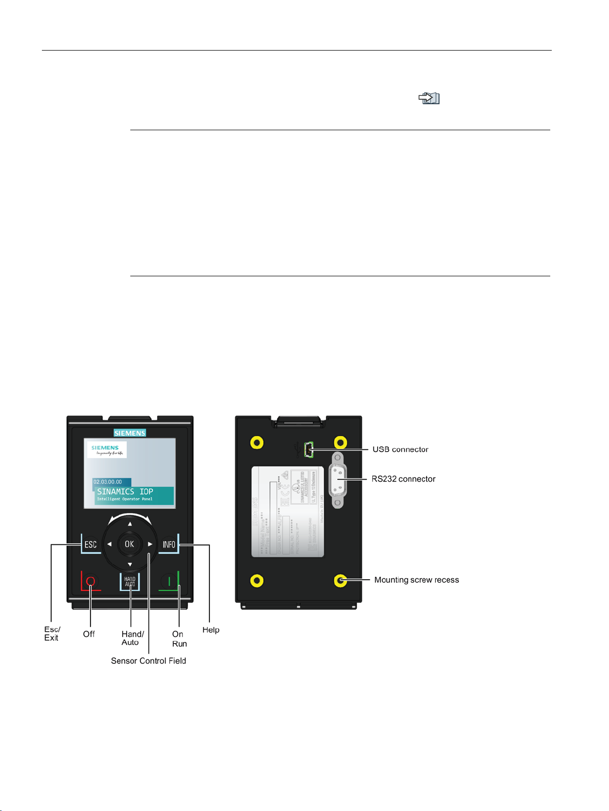
Figure 4-1 Layout of the IOP-2
The physical layout of the IOP-2 is shown below:
Intelligent Operating Panel 2 (IOP-2)
12 Operating Instructions, 06/2020, FW V2.6, A5E39549448B AH
Page 15

Overview
Key
Function
The Sensor Control Field has the following functions:
The ON key has the following functions:
When the converter is running in HAND mode, the motor stops when switched to AUTO.
The OFF key has the following functions:
down time set in parameter P1121.
The ESC key has the following functions:
When using the ESC key in the parameter editing mode, no data is saved unless the OK key is pressed first.
4.2 Layout and functions
The IOP-2 is operated by using a Sensor Control Field and five additional buttons. The specific
functions of the Sensor Control Field and buttons are shown in the table below.
Table 4- 1 Function of the IOP-2 controls
• In a menu, sliding your finger around the Sensor Control Field changes the selection.
• When a selection is highlighted, pressing the OK button in the centre of the Sensor Control Field confirms
the selection.
• When editing a parameter, sliding your finger around the Sensor Control Field changes the displayed
value; clockwise increases the value and anti-clockwise decreases the displayed value.
• When editing parameter or search values there is a choice to edit individual digits using the arrow keys or
an entire value using the Sensor Control Field. The speed with which you slide your finger around the
Sensor Control Field increases or decreases the speed of movement of the cursor.
• The Sensor Control Field has integrated arrows which can be used to navigate through the menus and
individual digits in the inputs fields.
• In AUTO mode can be changed by pressing the HAND/AUTO key.
• In HAND mode the converter is started - the converter status icon starts turning.
Notes:
For Control Units with firmware versions less than 4.0:
When running in AUTO mode, HAND mode cannot be selected unless the converter is stopped.
For Control Units with firmware versions 4.0 or greater:
When running in AUTO mode, HAND mode can be selected and the motor will continue to run at the last
selected setpoint speed.
• If pressed for longer than 3 seconds the converter will perform an OFF2; the motor will then coast down
to a standstill. Note: 2 presses of the OFF key within 3 seconds will also perform and OFF2.
• If pressed for less than 3 seconds the following actions will be performed:
– If in AUTO mode the screen will display an information screen stating that the command sources is
AUTO and can be changed using the HAND/AUTO key. The converter will not be stopped.
– If in HAND mode the converter will perform an OFF1; the motor will come to a standstill in the ramp-
• If pressed for less than 3 seconds the IOP-2 returns to the previous screen or if a value has been edited,
the new value is not saved.
• If pressed longer than 3 seconds the IOP-2 returns to the status screen.
Intelligent Operating Panel 2 (IOP-2)
Operating Instructions, 06/2020, FW V2.6, A5E39549448B AH
13
Page 16
Overview
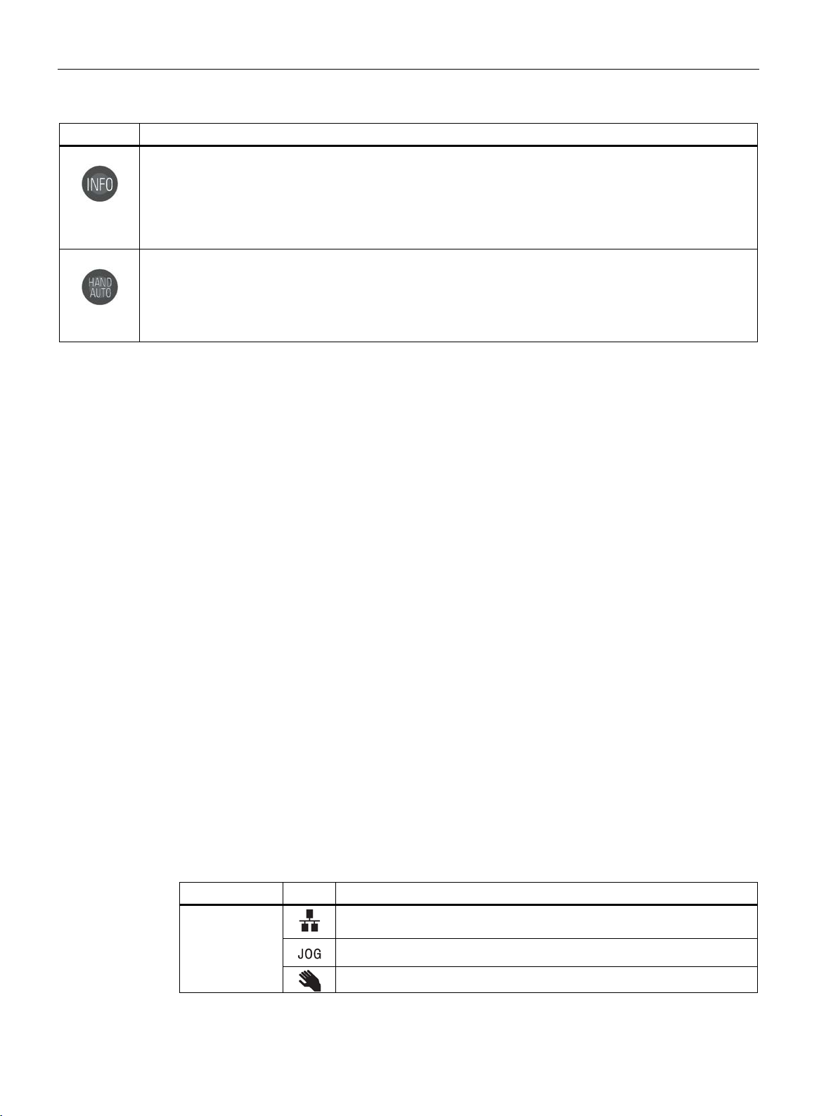
Key
Function
The INFO key has the following functions:
The HAND/AUTO key switches the command source between HAND and AUTO mode.
the standard status screen.
Function
Icon
Remarks
Command
Auto - the converter receives the command signals from the network
controller
Displayed when the JOG function is active
Hand - the converter is under control of the IOP-2
4.3 Screen icons
• Displays additional information for the currently selected item.
• Pressing the INFO key again will display the previous screen.
• Pressing the INFO key during power-up of the IOP-2 will place the IOP-2 in DEMO mode. To exit DEMO
mode, power-cycle the IOP-2.
• HAND sets the command source to the IOP-2.
• AUTO sets the command source to an external source, for example, fieldbus.
Note: When switching from the HAND mode back to the AUTO mode, the setpoint screen will change back to
Locking and unlocking the keypad
The keypad can only be locked once the power-up cycle has been completed. If the keys are
activated before the power-up cycle is completed, the IOP-2 will enter the DEMO mode.
To lock the IOP-2 keypad press ESC and INFO simultaneously for 3 seconds or more. To
unlock the keypad press ESC and INFO simultaneously for 3 seconds or more.
DEMO mode
DEMO mode allows the IOP-2 to be used for demonstration purposes without affecting the
converter to which it is connected. Menus can be navigated and functions selected, but all
communications with the converter are blocked to ensure that the converter does not react
to any commands issued from the IOP-2.
To enter the DEMO mode it is necessary to do a long press of the ESC key or INFO key during
the power-up cycle. The IOP-2 must be power cycled again to exit the DEMO mode.
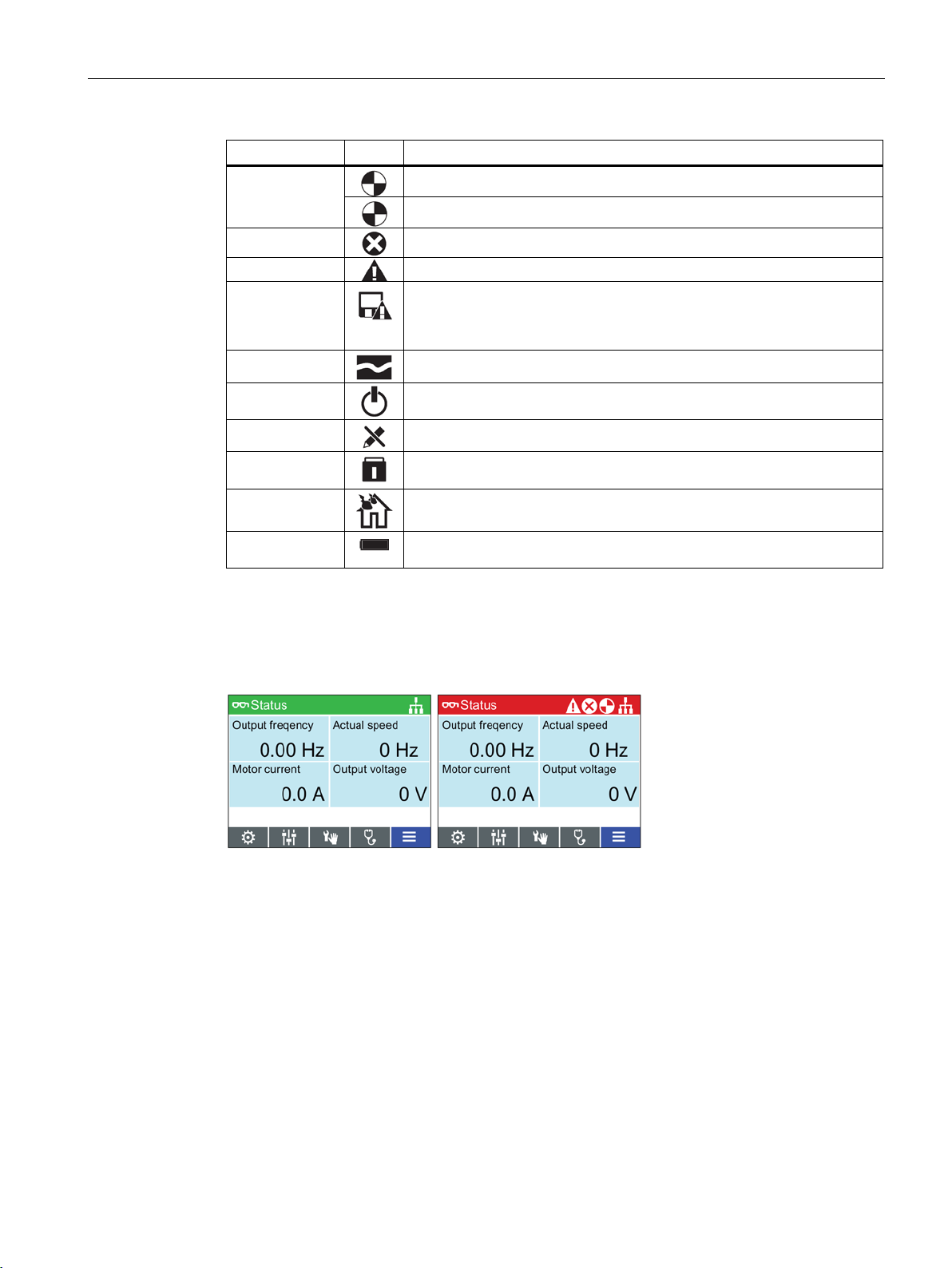
4.3 Screen icons
Overview
The IOP-2 displays a number of icons at the top right-hand edge of the display to indicate
various states or current conditions of the converter. These icons are explained in the table
below.
Table 4- 2 Screen icons
source
Intelligent Operating Panel 2 (IOP-2)
14 Operating Instructions, 06/2020, FW V2.6, A5E39549448B AH
Page 17
Overview
Function
Icon
Remarks
Inverter status
Icon rotates when the motor is running
Fault pending
Alarm pending
Saving to RAM
Indicates that all recent changes to parameters have been saved in RAM
must be performed.
PID autotuning
Hibernation
mode
Write Protection
Parameters cannot be modified.
Know How
Protection
Parameters cannot be viewed or modified.
ESM Essential Services Mode
Battery
condition
The battery status is only shown when the IOP-2 Hand-held kit is used.
Red
Error status: Indicates a fault is active and the Control Unit is in an error condition.
White
Neutral status: The IOP-2 has no connection to the Control Unit.
Green
Run status: The converter is running with no active faults. Active alarms will be
displayed on the status bar.
Blue
Blue denotes the selected item on the screen.
4.3 Screen icons
only. In the event of a power failure, then all recent changes saved to
RAM will be lost. To prevent loss of parameter data a RAM-to-ROM save
Screen faults and alarm indicators
When a fault or an alarm is active on the converter the top label on the screen will turn red.
The top label will remain red until the fault or warning has been acknowledged or rectified.
Figure 4-2 Fault and alarm notifications
Use of screen colours
A brief explanation of the use of the different colours on the screen is given below:
Intelligent Operating Panel 2 (IOP-2)
Operating Instructions, 06/2020, FW V2.6, A5E39549448B AH
15
Page 18
Overview
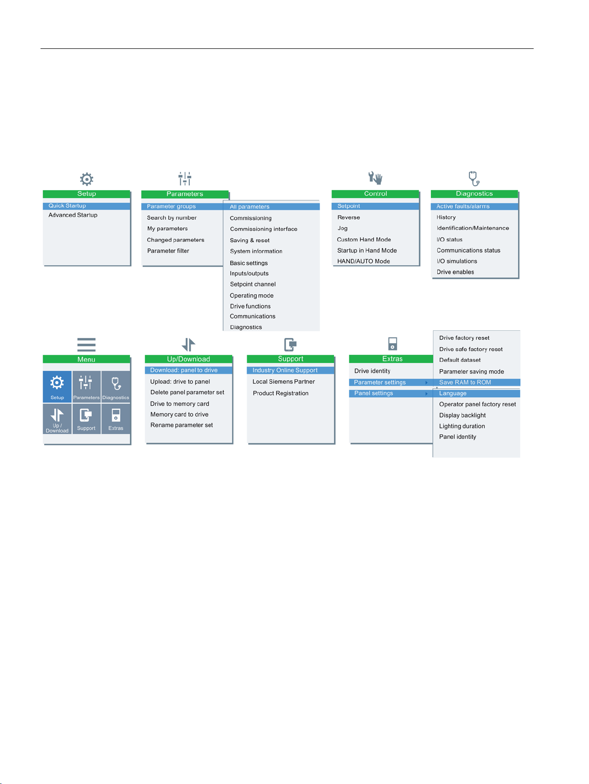
4.4 Menu structure
4.4 Menu structure
Overview
The Menu structure of the IOP-2 is shown in the figure below.
Figure 4-3 IOP-2 menu structure
Intelligent Operating Panel 2 (IOP-2)
16 Operating Instructions, 06/2020, FW V2.6, A5E39549448B AH
Page 19
5
Note
IOP
The IOP-2 has no internal power supply and derives its power directly from the Control Unit of
the converter through the RS232 interface. The IOP
derives its power through the USB connection.
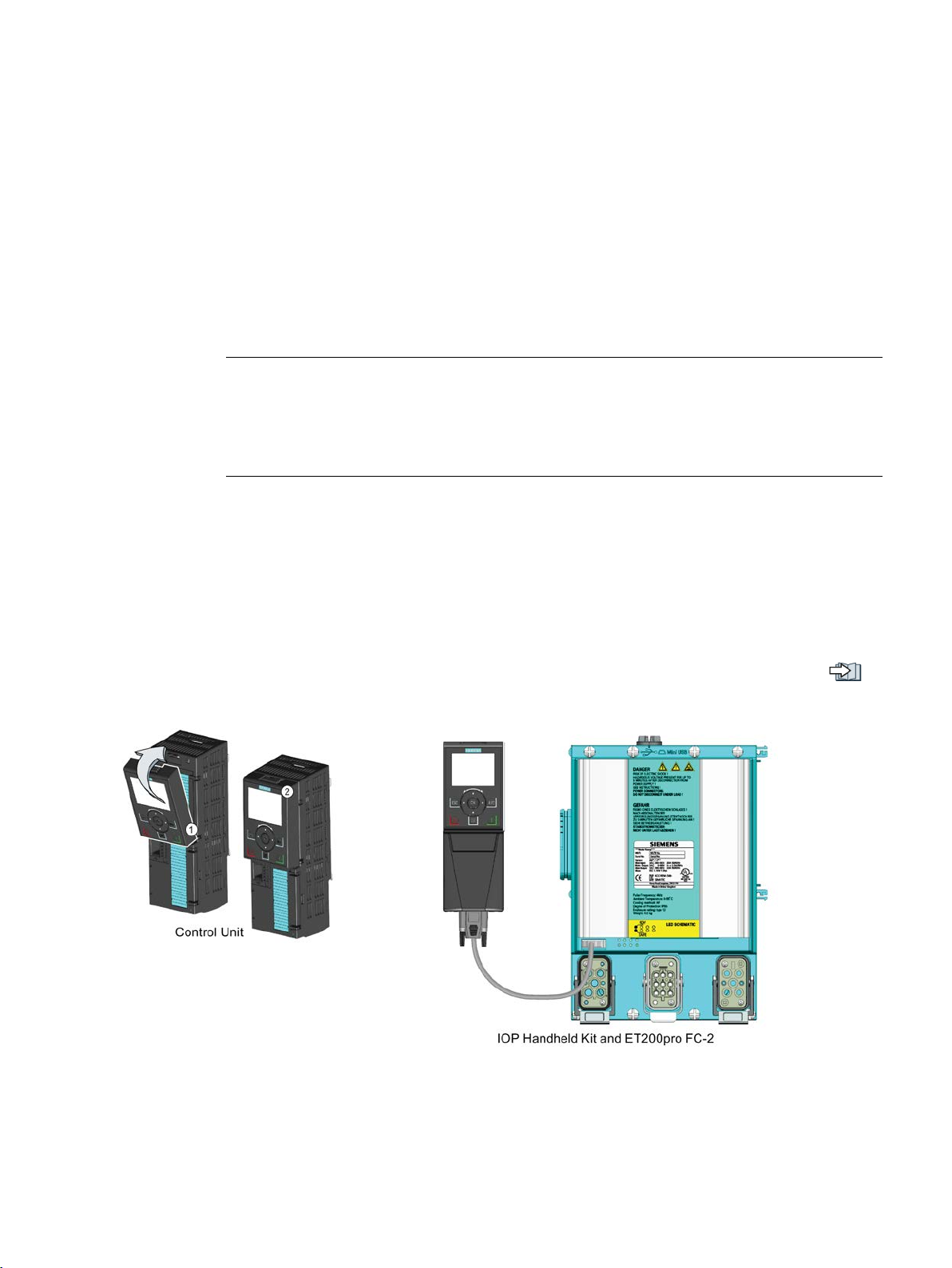
5.1 Fitting the IOP-2
Fitting the IOP-2 to the Control Unit
-2 power supply
To fit the IOP-2 to the converter Control Unit the following procedure should be performed:
-2 can also be connected to a PC and
1. Place the bottom edge of the IOP-2 casing into the lower recess of the Control Unit housing.
2. Push the IOP-2 forward until the top fastening clicks into place on the Control Unit housing.
To use the IOP-2 with a decentralized drive, for example an ET200pro FC-2, an IOP-2
Handheld kit is required and an optical cable. The IOP-2 Handheld kit and optical cable are
fitted as shown in the following figure.
The order details of both the IOP-2 Handheld kit and the optical cable are given in the
Introduction (Page 11).
Figure 5-1 Fitting IOP-2 on CU and ET200pro FC-2
Intelligent Operating Panel 2 (IOP-2)
Operating Instructions, 06/2020, FW V2.6, A5E39549448B AH
17
Page 20
Installation
Note
Saving and cloning of the IOP
All changes made to an IOP
the IO
To copy/clone all this data to another, or multiple IOP
Customer parameter sets (Page 61).
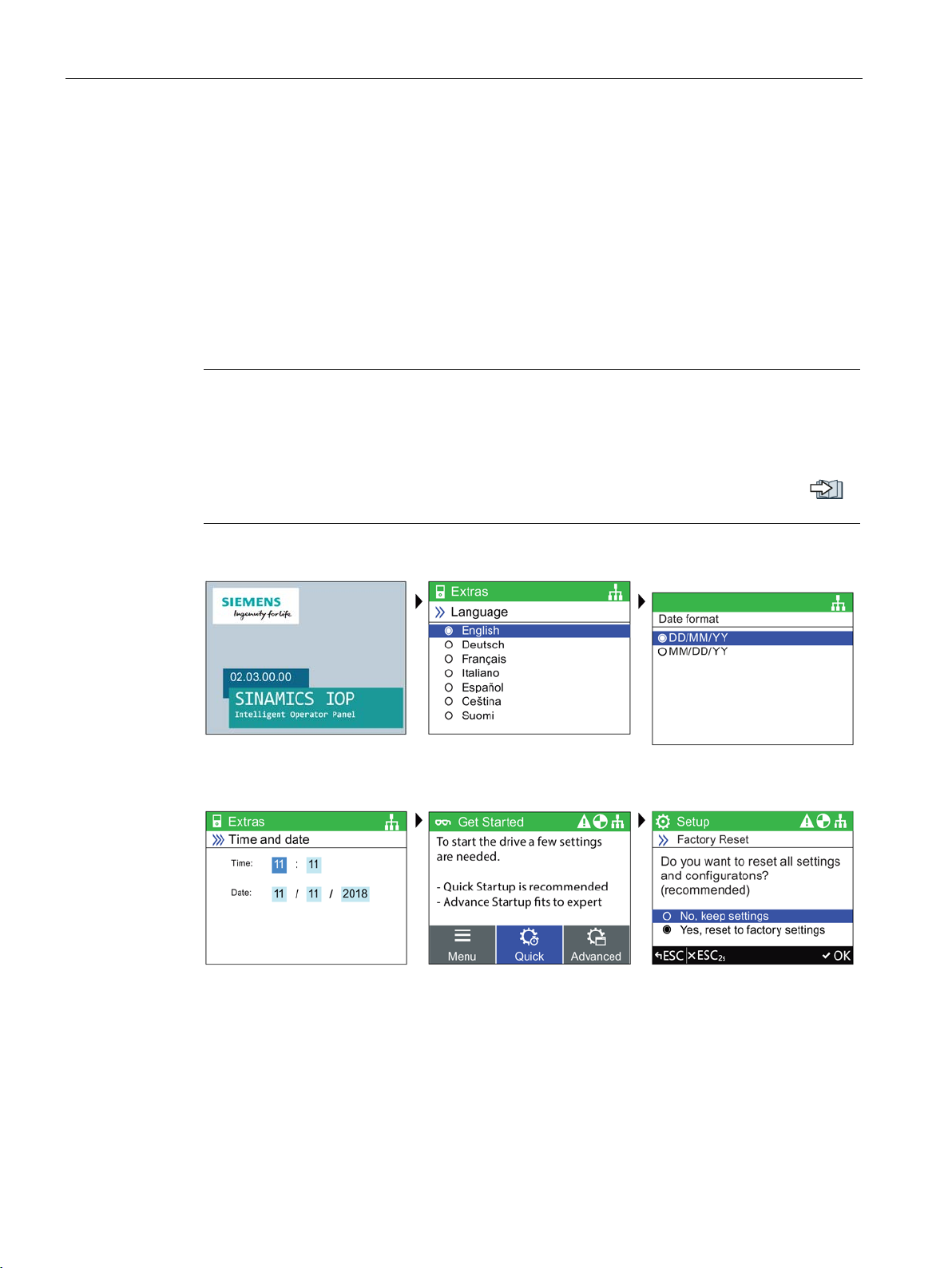
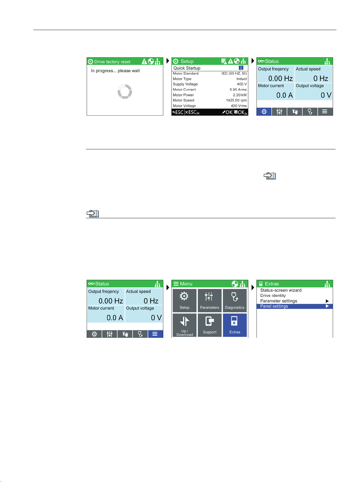
Splash screen is displayed
Select the required language
Select date format
Set correct date and time
Select Quick Startup
Select "Yes, reset to factory
settings"
5.2 Initial set-up
5.2 Initial set-up
Initial set-up sequence
Once the IOP-2 is fitted and powered-up it will automatically detect the type of Control Unit
and Power Module to which it has been fitted. On first-time use, the IOP-2 automatically
displays the option to select the default language and allow the time and date to be set (if the
Control Unit to which the IOP-2 is fitted has a real-time clock). The IOP-2 will then display the
choice between "Quick Startup" or Advanced Startup"; "Quick Startup" is the recommended
selection. The procedure is outlined below.
-2 configuration data
-2 configuration, included all saved parameter sets, are stored in
P-2 file structure in the "user" folder.
-2s, the procedures are shown in
Intelligent Operating Panel 2 (IOP-2)
18 Operating Instructions, 06/2020, FW V2.6, A5E39549448B AH
Page 21
Installation
Wait until the factory reset is
finished
Change or confirm settings
Status screen on completion
Note
The IOP
Startup setups. For information on Firmware upgrades, please see
2
firmware
The status screen can be reconfigured to show a number of different views and
values; these can be configured using the "Status Screen Wizard" in the "Extras" menu, see
Extras Menu (Page 65).
Select Menu
Select Extras
Select Panel settings
5.2 Initial set-up
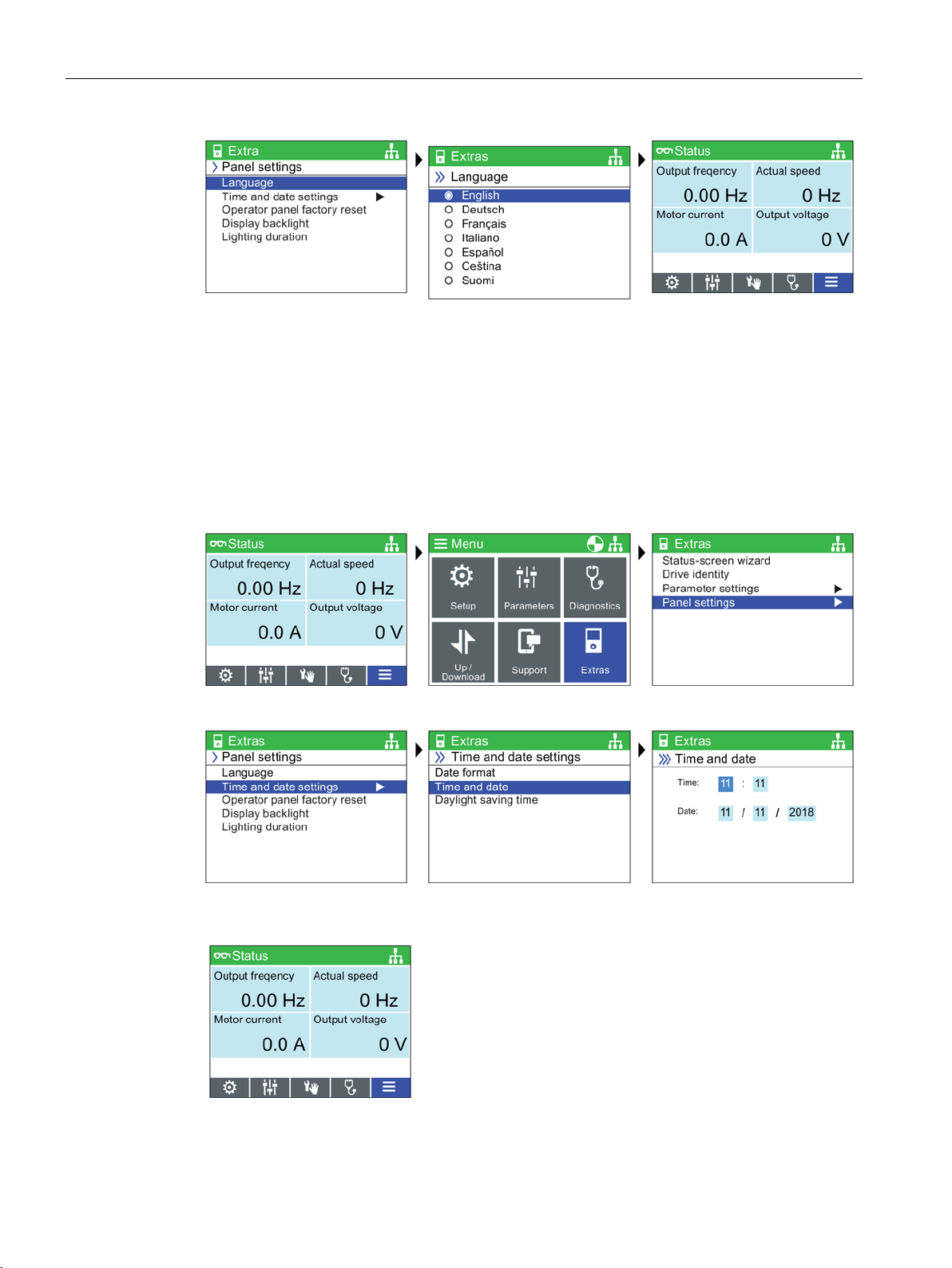
Language selection
The IOP-2 on first start-up will display the language screen for the user to select their required
language, should you wish to select you language manually, the following actions should be
performed:
-2 is delivered with all available languages and the Quick Startup and Advanced
Upgrading the IOP-
(Page 25).
types of
Intelligent Operating Panel 2 (IOP-2)
Operating Instructions, 06/2020, FW V2.6, A5E39549448B AH
19
Page 22
Installation
Select language
Select required language
Press and hold down ESC for
Status Screen
Select Menu
Select Extras
Select Panel settings
Select Time and date settings
Set the Time and date
settings
Set time and date
Press and hold down ESC for
Status Screen
5.2 Initial set-up
All available languages are delivered with the IOP-2.
Setting time and date
When the IOP-2 is first fitted to a Control Unit, which has a real-time clock, it will
automatically display the time and date screen. Should you wish to manually set the time on
the IOP-2, the following actions should be performed:
Intelligent Operating Panel 2 (IOP-2)
20 Operating Instructions, 06/2020, FW V2.6, A5E39549448B AH
Page 23
Installation
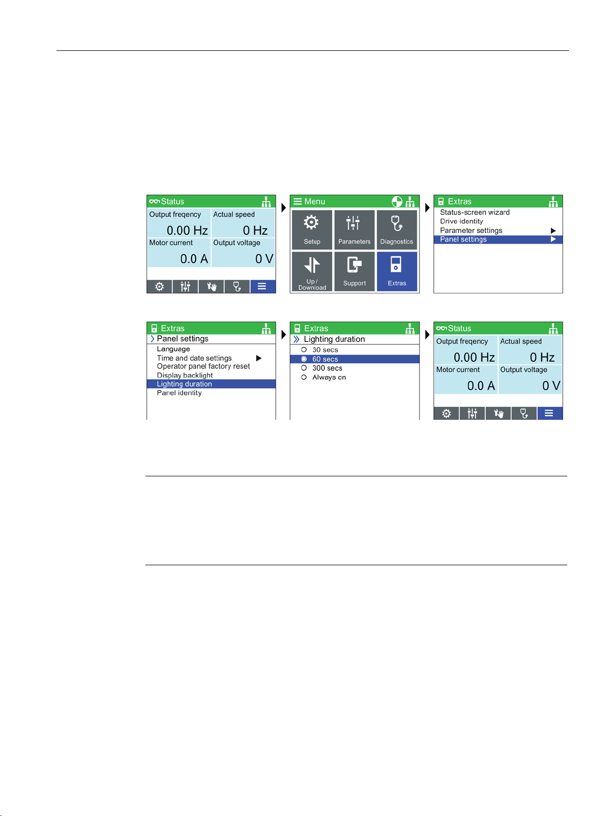
Select Menu
Select Extras
Select Panel settings
Select Lighting duration
Select Lighting duration time
Press and hold down ESC for
Status Screen
Note
Screen will flash when an active fault condition exists
When an active fault condition exists on the IOP
one minute then the screen will start to flash on and off. The screen will dim a few seconds
prior to the lighting duration time
been set to "Always on" the screen will not dim.
5.2 Initial set-up
The settings for time are normally done on the Control Unit if it has a Real-time Clock (RTC). If
the Inverter has an RTC the IOP-2 will take its settings from the Control Unit.
Lighting duration
To set the length of time that the display remains lit, the following actions should be
performed:
-2, if no key has been pressed for more than
-out period. If the screen is set to never dim, that is, it has
Intelligent Operating Panel 2 (IOP-2)
Operating Instructions, 06/2020, FW V2.6, A5E39549448B AH
21
Page 24

Installation
Select Menu
Select Extras
Select Panel settings
Select Display backlight
Select display backlight level
Press and hold down ESC for
Status Screen
5.3 Changing the Status screens
Display backlight
To change the intensity of the backlight, the following actions should be performed:
The display backlight setting will be automatically changed to the "Low" setting after 60
seconds from the last key press to extend the life of the display. When any key is pressed the
backlight setting will automatically return to the user setting.
5.3 Changing the Status screens
Changing the status screens
The status screens of the IOP-2 can show three different styles of screens.
• Bar graph view - This shows the selected data on up to two separate sliding bar scales.
• Scalar view - This shows the selected data as numerical values in up to four separate
quadrants on the screen.
• Trend view - This shows the selected data as two separate real-time plots on the screen.
Intelligent Operating Panel 2 (IOP-2)
22 Operating Instructions, 06/2020, FW V2.6, A5E39549448B AH
Page 25

Installation
5.3 Changing the Status screens
Select a different status screen
To select a different status screen the following procedure should be performed:
1. When the status screen is displayed, use the UP arrow key to enter the screen selected
mode.
2. Using the LEFT and RIGHT arrow keys, select the required status screen.
3. Press ESC or the DOWN arrow key to accept the new status screen and exit the screen
selection mode.
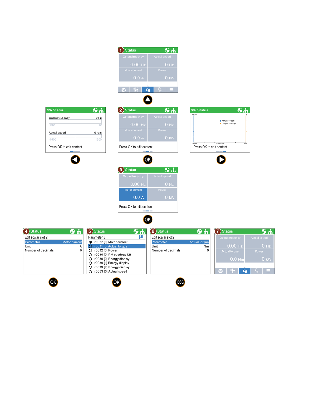
Modify the display data
To modify the data that is displayed on the status screen, the following procedure should be
performed:
1. Use the UP key to enter the status screen selection mode.
2. Press OK to edit the displayed data.
3. Use the arrow keys to navigate around the screen until the data you wish to change is
highlighted. Press OK to edit the highlighted data.
4. Press OK to edit the parameter to be displayed.
5. Select the new parameter you wish to be displayed. Press OK to accept the new selection.
6. The new parameter selection is shown in the list. Press ESC or the DOWN arrow key to return
to normal functions of the IOP-2.
7. The status screen is shown with the new data values and the screen menu is shown.
An overview of the basic procedures is shown in the figure below.
Intelligent Operating Panel 2 (IOP-2)
Operating Instructions, 06/2020, FW V2.6, A5E39549448B AH
23
Page 26
Installation
5.4 User definable labels on status screen
Figure 5-2 Selecting and modifying the IOP-2 status screens
5.4 User definable labels on status screen
User definable labels
User defined labels allow the user to customize the labels that appear on the status screen of
the IOP-2.
There are a maximum of four labels that can be defined and they are located on the IOP-2 in
the "cps" folder. The IOP-2 must be connected to the PC via the USB connection and in "Mass
Intelligent Operating Panel 2 (IOP-2)
24 Operating Instructions, 06/2020, FW V2.6, A5E39549448B AH
Page 27

Installation
5.5 Upgrading the IOP-2 firmware
Storage" mode to access the files on the IOP-2.The files are basic text files and can be opened
with any basic text editor. The default label names are "default", when the labels have the
"default" text, the IOP-2 will ignore the labels. There are the following restrictions when
creating your own labels:
• A maximum of 20 characters for each label name.
• The characters that can be used conform to the normal windows file naming conventions.
• The number of labels are restricted depending on the type of status screen view that is
selected in the "Status screen wizard". See
Extras Menu (Page 65).
The four files are named:
• BotLeft.txt
• BotRight.txt
• TopLeft.txt
• TopRight.txt
The file names relate to the area of the status where they will appear.
Simply selected the file you wish to use as a label; open it with a text editor, change the
name and then save it back to the same location in the IOP-2 file system. If the file name
itself is changed the IOP-2 will not recognize the label.
An example of the status screen with new label names (using all four text files) is shown in
the figure below.
Figure 5-3 Example of defining your own labels
5.5 Upgrading the IOP-2 firmware
Upgrading the IOP-2 firmware
The IOP-2 contains firmware, which can be upgraded by the user by means of a firmware
upgrade. To perform the upgrade of the IOP-2 firmware the following steps should be
performed.
1. Plug the IOP-2 into a PC using the USB connection. Note: Connect the IOP-2 only to an
internal USB interface. Do not use an USB interface which is connected to your PC externally
(e.g. via a docking station, external USB-Hub or desktop PCs with front sockets).
2. The IOP-2 will automatically enter the "Mass Storage" mode.
Intelligent Operating Panel 2 (IOP-2)
Operating Instructions, 06/2020, FW V2.6, A5E39549448B AH
25
Page 28

Installation
Note
English language is mandatory
The English language file is essential to the correct functioning of the IOP
cannot be deleted.
5.5 Upgrading the IOP-2 firmware
3. Open the file explorer on the PC.
4. Navigate to the IOP-2 (removable media). Note: Back up data (e.g., readme, parameter
records) that you will need later on the connected PC.
5. Format the IOP-2 (do not use quick formatting). Set the size of the allocation units to 2048
bytes (FAT Standard).
6. Go to the Service and Support site at the link shown below.
7. Download the zip file with the current firmware of the IOP-2 into a folder on the PC and
unpack it into a separate directory.
8. Copy the downloaded files from the PC directory directly into the IOP-2 folder (the copying
process takes approximate 6 minutes).
9. When the copying has been completed, wait approximate 5 seconds before disconnecting
the IOP-2 from the USB port. The new firmware is now available on the IOP-2 and you can
now connect the IOP-2 to a SINAMICS G inverter.
10.When you turn on the SINAMICS G inverter, the IOP-2 will automatically upgrade.
Only IOP-2 firmware update packages obtained through the Siemens Service and Support
website at the following link should be used:
IOP-2 firmware download: IOP-2 Firmware upgrade
(https://support.industry.siemens.com/cs/ww/en/view/109762019
Reading the OSS License
The IOP-2 contains open-source software (OSS). The OSS comprises open-source text and
satisfies special license terms. If you wish to read the license terms, see: efs/readme_OSS.zip
on the IOP-2.
-2 and therefore
)
Intelligent Operating Panel 2 (IOP-2)
26 Operating Instructions, 06/2020, FW V2.6, A5E39549448B AH
Page 29

6
WARNING
not produce an unpredicted or unsafe effect on personnel, equipment or premises.
WARNING
Safe and stable state of the converter
dangerous conditions exist.
CAUTION
Default datasets
changed to the other datasets, the Setups may not function correctly.
Overview
The IOP-2 Setups are question-driven environment that assist the user to set-up various
functions and applications of the converter.
Motor Identification (Motor ID) function will run automatically
Using the "Standard Drive Control" or "Dynamic Drive Control" in Quick Startup, the Motor ID
function, if selected, is activated at the end of the commissioning squenence.
The motor identification (motor ID) function, after the completion of the Quick Startup,
upon the first startup, will start automatically after approx. 8 to 30 s and accelerate the
motor to the setpoint speed.
This action must be taken into account when the Quick Startup procedure has been
completed, to ensure that the first ON/RUN command when given for your application, does
During the setup of the converter it is essential to ensure that the system is in a safe and
stable state, as some setup processes have the potential to start the motor. Therefore it is
important to secure any loads and ensure that should the motor start, no potentially
The Setups use the default Drive datasets (DDS0 and CDS0), if the default datasets are
Intelligent Operating Panel 2 (IOP-2)
Operating Instructions, 06/2020, FW V2.6, A5E39549448B AH
27
Page 30

Setup Menu
CAUTION
application.
6.1 Example Setups
6.1 Example Setups
Overview of Setup
The following example of how Setup work on the IOP-2 are purely for demonstration purpose
only.
Before setting up an application
Prior to using Setup, it is essential that the user's Control Unit and Power Module have been
installed and wired correctly, in accordance with the requirements of the user's application.
This is extremely important in the case of setting up safety-integrated applications. All
inputs and outputs must be defined and configured before any setting up can take place,
including the observation and adherence of all local, national and international safety
regulations required for the user's application and all devices utilized by the user's
Quick Startup/Advanced Startup
Quick Startup
The Quick Startup procedure is all the user needs to setup the converter in quickly and easily.
The Quick Startup allows the user to configure the following converter data:
• Motor Standard
• Motor Type
• Supply Voltage
• Motor Current
• Motor Power
• Motor Speed
• Motor Voltage
• Motor Frequency
• Minimum Frequency
• Maximum Frequency
• Ramp-up Time
• Ramp-down Time
• I/O Setup
Intelligent Operating Panel 2 (IOP-2)
28 Operating Instructions, 06/2020, FW V2.6, A5E39549448B AH
The default settings of the converter will be automatically read into the IOP-2, but it is
recommended that you check that these settings are correct for your converter by comparing
the settings with the data from the converter and motor rating labels.
Page 31

Setup Menu
6.1 Example Setups
Advanced Startup
The Advanced Startup provides the user with a more comprehensive range of settings that
can be configured for specific requirements and applications. The settings that are available
are as follows:
• Drive Information: This displayed detailed information about the connected Control Unit
and Power Module.
• Factory Reset: This allows the converter to be reset to the factory default settings.
• Hardware options: This allows the configuring of and Output Filter and a Braking Resistor.
• Control Type: This allows the selection of the control types, Standard Drive Control,
Dynamics Drive Control and Expert. A brief explanation of each Control Type is given
below.
• Motor Data: This allows the user to configure the Motor settings which consist of the data
presented in the Quick Setup.
• Limit Settings: This gives the user the opportunity to setup the dynamics settings of the
converter.
• Optimization: This allows the user to optimize the converter for technological applications
and ensure that the correct motor data will be used.
Control Types
• I/O Setup: This allows the user to configure the Input and Output settings of the converter.
The I/O configuration is pre-assigned using macros so that no further settings are
necessary.
• Fieldbus Setup: This allows the user to configure the interface settings.
• Application Setup: This allows the user to configure the application specific functions of
the converter.
For more detailed information of the application classes, see the document at the link below:
Application classes (https://support.industry.siemens.com/cs/ww/en/view/109480663
)
Standard Drive Control
• Standard Drive Control is preset for the Power Modules PM240, PM240-2 and G120C in
frame sizes FSA-C. This application class can, for example, be used for the following
applications:
– Pumps, fans and compressors with flow characteristic
– Wet or dry beam technology, mills, mixers, kneaders, crushers, agitators
– Horizontal conveyor technology (conveyor belts, roller conveyors, chain conveyors)
– Basic spindles
Intelligent Operating Panel 2 (IOP-2)
Operating Instructions, 06/2020, FW V2.6, A5E39549448B AH
29
Page 32

Setup Menu
WARNING
setting for p1900 = 2.
Note
Macro source selection
During the Quick Startup process, the user will be presented with a list of preset macros that
determine the configuration of the converter. Every Control Unit Operating Instructions
contain a list of the macros that are specific for that particular Contro
wiring configurations for each macro. For further information, see the relevant Operating
Instructions.
6.1 Example Setups
Dynamic Drive Control
• Dynamic Drive Control is preset for the Power Modules PM240, PM240-2 and PM330 in
frame sizes ≥ FSD. This application class can, for example, be used for the following
applications:
– Pumps and compressors with displacement machine
– Rotary furnaces
– Extruders
– Centrifuges
Expert
• Expert is fixed assigned to the Power Modules PM230, PM250 and PM260 as soon as for
G120D, G110M and ET200pro FC-2. This setting corresponds to the existing Setup and
will also be assigned to existing projects. It allows the flexibly setup of the converter, but
requires a detailed understanding of the drive.
Motor data identification (motor ID)
When selecting motor data identification (motor ID) with subsequent ramp-up to the
setpoint speed (p1900 = 11 or 12; 12 = standard setting based on SINAMICS Firmware V4.7
SP3 with "Standard Drive Control" and "Dynamic Drive Control"), the motor is, upon the first
Power ON command, directly accelerated to the setpoint speed, following a short delay time
caused by the motor ID (approx. 15 to 30 s). From SINAMICS Firmware V4.7 SP6 the default
l Unit and show the
Intelligent Operating Panel 2 (IOP-2)
30 Operating Instructions, 06/2020, FW V2.6, A5E39549448B AH
Page 33

Setup Menu
NOTICE
motor rating label, an example of which is included in the Operating Instructions for your
"Installation" section of the Operating Instructions for your converter.
6.1 Example Setups
Info Screens
Info Screens (Information Screens) are accessed with a press of the INFO button. There may
be multiple INFO screens and these you can navigated between each screen using the arrow
keys.
Figure 6-1 Using the INFO button
6.1.1 Quick Startup with the IOP-2
Quick Startup
Requirements prior to using the Quick Startup
• The user must be fully conversant with all safety instructions as detailed in the
"Fundamental Safety Instructions" section of the Operating Instructions for your
converter.
• The converter must be installed and checked as per the relevant instructions in the
"Installation" sections of the converter Operating Instructions.
• Macro source selection: During the Quick Startup process, the user will be presented
with a list of preset macros that determine the configuration of converter. Every Control
Unit Operating Instructions contain a list of the macros that are specific for that
particular Control Unit and show the wiring configurations for each macro. For further
information, see the relevant Operating Instructions.
• The information required to be input into the Quick Startup process can be found on the
converter.
• If the motor is to operate with the "87 Hz characteristic"; You need to use the "Advanced
Startup" process and you need to connect the motor in Delta (Δ), this is shown in the
Intelligent Operating Panel 2 (IOP-2)
Operating Instructions, 06/2020, FW V2.6, A5E39549448B AH
31
Page 34

Setup Menu
Select Setup
Select Quick Startup
Select Factory Reset (yes or
no)
Factory Reset begins
Select Motor Standard
Select mains frequency and
units
Select Motor Type
Select Input Mode
Enter Motor Data or Motor
Code
Select Supply Voltage
Enter Supply Voltage from
rating label
Select Motor Current
6.1 Example Setups
Intelligent Operating Panel 2 (IOP-2)
32 Operating Instructions, 06/2020, FW V2.6, A5E39549448B AH
Page 35

Setup Menu
Enter Motor Current from
rating label
Select Motor Power
Enter Motor Power from
rating label
Select Motor Speed
Enter Motor Speed from
rating label
Select Motor Voltage
Enter Motor Voltage from
rating label
Select Motor Frequency
Enter Motor Frequency
Select Min. Freq.
Enter the required Min. Freq.
Select Max. Freq.
6.1 Example Setups
Intelligent Operating Panel 2 (IOP-2)
Operating Instructions, 06/2020, FW V2.6, A5E39549448B AH
33
Page 36

Setup Menu
Enter the required Max. Freq.
Select Ramp-up Time
Enter required Ramp-up Time
Select Ramp-down Time
Enter required Ramp-down
Time
Select I/O Setup
Select the required Macro
Save the Settings
Saving Settings in progress
Settings have been saved
Motor ID ran on next ON
command
Setup up completed
6.1 Example Setups
Intelligent Operating Panel 2 (IOP-2)
34 Operating Instructions, 06/2020, FW V2.6, A5E39549448B AH
Page 37

Setup Menu
The settings for the function at the default settings.
The settings for the function have been changed and saved.
The settings for the function must be checked to ensure the safety settings are correct.
The settings for the function must be checked and corrected if necessary.
This icon indicates that information is available on the selected function by pressing the
INFO key.
6.1 Example Setups
6.1.2 Advanced Startup with the IOP-2
Advanced Startup overview
Advanced Startup is a commissioning process for all application which provides a high degree
of flexibility when dealing with the converter settings. The provided settings allow an
optimized adaption of the converter to the target application.
The setup process will guide the user through the commissioning process by presenting a
number of categories where the user can choose the necessary options and values to
commission the converter and motor.
At the conclusion of the setup process, the data can be saved to the converter's memory.
Setup Icons
The setup process uses a number of very important icons to indicate the status of the
settings. A description of the various icons is given below.
Advanced Startup
The Advanced Startup process is outlined below and is should be remembered that the
screenshots are for example purposes only and may vary from your own IOP-2 display,
depending on the firmware version and the actual converter that is being commissioned.
Intelligent Operating Panel 2 (IOP-2)
Operating Instructions, 06/2020, FW V2.6, A5E39549448B AH
35
Page 38

Setup Menu
Advanced Startup Menu
This screen lists all the advanced settings that are available for
the user to modify for their sp
Drive Information
This screen provides general information concerning the used
converter configuration (Power Module, Control Unit and the
Intelligent Operator Panel IOP
Factory Reset
This function resets all the parameters to their factory default
settings. Any safety parameters that have been modified
not be reset.
It is recommended that you reset to the factory settings before
commissioning the converter.
Hardware Options
This screen gives the user the opportunity to setup the
converter options, for example, an Output Filter or a Braking
Resistor.
Control Type
This screen allows the application class to be set.
Depending on the particular Power Module, the converter
selects the right application class and assigns the motor control
the appropriate default settings.
6.1 Example Setups
ecific application.
-2).
will
Intelligent Operating Panel 2 (IOP-2)
36 Operating Instructions, 06/2020, FW V2.6, A5E39549448B AH
Page 39

Setup Menu
Motor Data
The motor data stored here corresponds to the 4
standard motor with the same converter power.
For dynamic applications and when other OEM motors are in
operation, adaptation of the settings will need to be made.
Limit Settings
This screen give the user the opportunity to setup the dynamics
settings of t
motor speed, ramp
ramp
Optimisation
This screen makes is possible to optimise the converter for the
technological applications and ensures that the correct motor
data will be used.
I/O Setup
This screen allows the I/O configuration to be defined. The I/O
configuration is pre
settings are necessary.
Fieldbus Setup
This screen allows the communications interface settings on
the converter to be configu
6.1 Example Setups
-pole SIEMENS
he motor, for example, minimum and maximum
-up and ramp-down timings and OFF-3
-down time.
-assigned using macros so that no further
red.
Intelligent Operating Panel 2 (IOP-2)
Operating Instructions, 06/2020, FW V2.6, A5E39549448B AH
37
Page 40

Setup Menu
Application Setup
This screen allows the applications specific functions to be
config
presented with some default applications functions, depending
on the type of Control Unit that is being used. The user can
setup their own list of functions using the "Adjust function list"
feature which allows functions to be added to or removed from
the displayed list. A grey tick is displayed beside the functions
that have not been configured using the IOP
function has been configured using the IOP
shown beside the fu
If a function is removed from the list
disabled and the settings restored to the factory defaults for
that specific function.
6.1 Example Setups
ured. When "Application Setup" is selected, the user is
nction in the list.
-2 and when a
-2, a green tick is
- the function will be
Intelligent Operating Panel 2 (IOP-2)
38 Operating Instructions, 06/2020, FW V2.6, A5E39549448B AH
Page 41

7
Overview
The Control menu allows the user to change the following settings in real-time:
• Setpoint
• Reverse
• Jog
• Custom Hand mode
• Startup in Hand mode
• Hand/Auto disable
The control menu is accessed from the menu at the bottom-centre of the Status screen, as
shown below.
Figure 7-1 Select Control Menu
Intelligent Operating Panel 2 (IOP-2)
Operating Instructions, 06/2020, FW V2.6, A5E39549448B AH
39
Page 42

Control menu
Select Control
Select Setpoint
Use Touch-wheel to set the
Setpoint
Note
Setpoint in Hertz (Hz) for SINAMICS CU230P
The setpoint screen by default displays the motor speed as a percentage of the total possible
speed of the motor.
This behaviour changes for the SINAMICS CU230P
displayed in Hertz (Hz).
Select Control
Select Reverse
Select Off or On
7.1 Setpoint
7.1 Setpoint
Setting the Setpoint
The setpoint value determines the speed at which the motor runs as a percentage of its full
range of motion.
To change the setpoint, the following actions should be performed:
7.2 Reverse
Setting Reverse
The function of the reverse command is to set the direction of rotation of the motor from its
normal forward motion.
To reverse the direction of the motor, the following actions should be performed:
-2
-2 where the default setpoint value is
Intelligent Operating Panel 2 (IOP-2)
40 Operating Instructions, 06/2020, FW V2.6, A5E39549448B AH
Page 43

Control menu
Select Control
Select Jog
Select Off or On
Note
Selection of Jog frequencies
It is important that the Jog parameters P1058 (Jog right) and P1059 (Jog left) are set to the
required frequencies for the users application. The default jogging setpoint for both
parameters is 5
When the Jog left and Jog right (Jog1 and Jog 2) have been set; it is necessary to do a long
press of the "INFO" key to select the other jog mode.
7.3 Jog
7.3 Jog
Setting Jog
The Jog function, when selected will allow the motor to be manually rotated by a predetermined value with each press of
continuously until
is released.
To enable or disable the Jog function, the following actions should be performed:
. If is pressed continuously, the motor will rotate
Hz (150 rpm).
7.4 Custom Hand mode
Overview
The custom hand mode allows the user to setup a command source and setpoint source
directly from the Intelligent Operator Panel 2 (IOP-2).
When the custom hand mode has been set, the IOP-2 Sensor Control Field can be used as the
setpoint source.
The Auto mode is unaffected by any changes made by the custom hand mode function.
A breakdown of all the interconnection inputs are given in the table below.
Intelligent Operating Panel 2 (IOP-2)
Operating Instructions, 06/2020, FW V2.6, A5E39549448B AH
41
Page 44

Control menu
Standard interconnection
mode
Bit0
ON/OFF key
->
Bit0
ON/OFF1
Bit1
Two quick press of the OFF key
->
Bit1
OFF2
Bit2
A long press of the OFF key
->
Bit2
OFF3
Bit3
Reserved
->
Bit3
Inhibit/enable operation
Bit4
Reserved
->
Bit4
Ramp-function generator enable
Bit5
Reserved
->
Bit5
Continue ramp-function generator
Bit6
Reserved
->
Bit6
Setpoint enable
Bit7
Alarms menu acknowledge all
faults
->
Bit7
Acknowledge faults
Bit8
Jog 1 (Control menu)
->
Bit8
Jog 1
Bit9
Jog 2 (Control menu)
->
Bit9
Jog 2
Bit10
Reserved
->
Bit10
Control by PLC
Bit11
Change direction (Control menu)
->
Bit11
Direction of rotating - reversed
Bit12
Reserved
->
Bit12
Speed control enable
Bit13
Reserved
->
Bit13
Motorized potentiometer, setpoint,
increase
Bit14
Reserved
->
Bit14
Motorized potentiometer, setpoint,
decrease
Bit15
Reserved
->
Bit15
CDS selection
Standard interconnection
r8541
Speed setpoint from IOP-2
Connector Inputs (CI)
p8543
Effective speed setpoint in Custom
Hand mode
N_soll OP
-> Speed setpoint
Select Control
Select Custom Hand Mode
Select Custom Hand Mode On
7.4 Custom Hand mode
An example of setting up the custom hand mode is given in the instructions below.
Table 7- 1 Interconnection inputs for Status Word 1 in Custom Hand mode
r8540 STW 1 from IOP-2 Binector Inputs (BI) p8542 Effective STW1 in Custom Hand
Setting up Custom Hand mode example
Intelligent Operating Panel 2 (IOP-2)
42 Operating Instructions, 06/2020, FW V2.6, A5E39549448B AH
Page 45

Control menu
Select Control Parameter
Select required function
Select source of command
signal
Select the input that will
receive command signal
Select Setpoint Parameter
Select the setpoint signal
source
Select the input to receive the
setpoint signal
7.5 Startup in Hand mode
7.5 Startup in Hand mode
Overview
Intelligent Operating Panel 2 (IOP-2)
Operating Instructions, 06/2020, FW V2.6, A5E39549448B AH
Once the setpoint signal input has been selected, the IOP-2 will return to the Setpoint
selection screen then press ESC for >3 secs, to return to the status screen.
In this example, the converter is now setup to receive the ON/OFF1 command from Digital
Input 0 (DI0) and the speed setpoint from Analog Input 0 (AI0), from the controlling PLC.
Startup in Hand mode allows the converter, under the control of the Intelligent Operator
Panel (IOP-2), to startup in Hand mode automatically. The command source is then taken
from the off and on buttons of the IOP-2.
An example of setting up the Startup in Hand mode is given in the instructions below.
43
Page 46

Control menu
Select Control
Select Startup in Hand Mode
Set the required speed
setpoint as a percentage
value
Select Control
Select Hand/Auto Disable
Enter password (default:
00000000)
7.6 HAND/AUTO disable
Setting up Startup in Hand mode example
The IOP-2 will automatically return to the Control menu and show that "Startup in Hand
Mode" is "On".
The converter, after a power-cycle will automatically startup in Hand mode, but the attached
motor will not run until the run command is given by the buttons on the IOP-2.
7.6 HAND/AUTO disable
Overview
The HAND/AUTO disable function disables the HAND/AUTO key on the Intelligent Operator
Panel (IOP-2) and pressing the key will not produce any action by the IOP-2.
An example of setting up the Hand/Auto disable mode is given in the instructions below.
Setting up the HAND/AUTO disable function
Intelligent Operating Panel 2 (IOP-2)
44 Operating Instructions, 06/2020, FW V2.6, A5E39549448B AH
Page 47

Control menu
Select On: Hand/Auto from
PLC or DI
Enter password again or
create a new password
Select signal source
Select input to receive control
signal
Press ESC to return to Control
Menu
Note
Power
When the HAND/AUTO disable function is initiated the function will not become active until a
power
turned off, again, a power
function.
7.6 HAND/AUTO disable
The HAND/AUTO button is now disabled and local control of the IOP-2 cannot be activated by
the HAND/AUTO button. In this example, the converter is now setup to receive the
HAND/AUTO command from Digital Input 1 (DI1).
-cycle required to complete the HAND/AUTO disable function
-cycle of the IOP-2 has been performed. When the HAND/AUTO disable function is
-cycle of the IOP-2 is required to complete the deactivation of the
Intelligent Operating Panel 2 (IOP-2)
Operating Instructions, 06/2020, FW V2.6, A5E39549448B AH
45
Page 48

Control menu
7.6 HAND/AUTO disable
Intelligent Operating Panel 2 (IOP-2)
46 Operating Instructions, 06/2020, FW V2.6, A5E39549448B AH
Page 49

8
WARNING
Protection of project data files from unauthorized usage
with, for example, the use of credentials.
8.1 Menu overview
Overview
Transportation of project data files have to be secured by technical means, for example,
encrypted/signed emails, encrypted/signed USB-sticks etc., especially in the public internet.
Project data files have to be stored with restricted access within the OEM/end customer
area, for example, access restrictions to SharePoints, databases, etc. by user management
The "Menu" is selected from the five menu options at the bottom of the IOP-2 screen.
When the "Menu" option is selected the following functions are displayed:
• Wizards
• Parameters
• Diagnostic
• Up/Download
• Extras
By sliding your finger around the Sensor Control Field or using the arrow keys, the required
function can be highlighted. Pushing the OK confirms the selection and further sub-menus
will be displayed. Pressing ESC once will return the IOP-2 to the previous screen, a longer
press will return the display to the "Status" screen.
For information on the IOP-2 compatibility, see
Introduction (Page 11).
Intelligent Operating Panel 2 (IOP-2)
Operating Instructions, 06/2020, FW V2.6, A5E39549448B AH
47
Page 50

Menu
•
•
•
•
•
•
• Drive enables
When this option is selected the screen will display any active
faults and alarms that have not yet been acknowledged.
Each fault and alarm can be selected and by pressing the INFO
key
displayed.
When this option is selected the screen will display a list of all
previous faults and alarms with the time that they occurred.
Each fault and alarm can be selected and by pressing the INFO
key
displayed.
Displays specific technical information regarding the Control
Unit and Power Module to which the IOP
displayed. The actual information displayed depends on the
type of Control Unit and Power Module to which the IOP
connected.
8.2 Diagnostics
8.2 Diagnostics
Diagnostics menu
When the diagnostic function is selected the following options are presented:
Active faults/alarms
History
Identification/Maintenance
I/O status
Communications status
I/O simulation
Active faults/alarms
or the OK key, an explanation of the fault or alarm will be
History
or the OK key, an explanation of the fault or alarm will be
Identification/Maintenance
-2 is attached will be
Intelligent Operating Panel 2 (IOP-2)
48 Operating Instructions, 06/2020, FW V2.6, A5E39549448B AH
-2 is
Page 51

Menu
This option displays a list of the digital and analog inputs and
outputs of the converter and their current status.
This is an information screen and cannot be changed.
Pressing ESC will return the display to the previous menu.
In the example shown opposite, the status of the digital inputs
are displayed.
This option displays the status of the fieldbus interface and the
d
status words and control word lengths.
In the example shown opposite, the status of the fieldbus
communications is shown.
WARNING
Loss of control of the converter
simulation is activated, then only the I/O simulation can be used to stop the converter.
8.2 Diagnostics
I/O status
Communications status
etails of the settings for the data exchange, for example
I/O simulation
If the converter is started using the I/O simulation and the IOP-2 is removed from the
converter it will not be possible to stop the converter running the motor. If the I/O
Intelligent Operating Panel 2 (IOP-2)
Operating Instructions, 06/2020, FW V2.6, A5E39549448B AH
49
Page 52

Menu
The IOP-2 simulation screen allows digital and analog IOs to be
simulated without the requirement for external signals. These
features are of great benefit during commissioning and fault
finding, as the user can quickly simulate a situation without
using w
For example:
•
•
•
Th
•
•
•
The drive enables screen displays a list of all the current
enabling signals for the converter. If the enable signal is
present and active it will be selected
not present and is not active it will be unselected
This screen is read
8.2 Diagnostics
ires, tools and external equipment.
A digital input can be made high without any wires in the
terminals.
An analog input or output can be driven to any value
without any wires in the terminals.
A simulation can be overridden and made high.
e screen presents the following options:
I/O - Three I/Os can be simulated - two digital and one
analog.
Status - this indicates the real-time status of the input or
output. If the square is shaded then the input or output
signal is present. This is a read-only section of the screen.
Control - this column of the screen displays the present
status of the input or output and can be altered.
Drive enables
-only and is for information purposes only.
Intelligent Operating Panel 2 (IOP-2)
50 Operating Instructions, 06/2020, FW V2.6, A5E39549448B AH
. If the enable signal is
☐.
Page 53

Menu
The parameter menu allows the user extensive functionality
and access to all the converter parameters. When this option is
selected the user is given the opportunity to perform
parameter orientated functions grouped in the following
manner:
•
•
•
•
•
When searching through any large parameter list, the Fast
scroll function will automat
their finger around the Sensor Control Field in a fast motion.
A large blue box will appear on the screen, showing the
current parameter number, with each scroll the number will
increase by 100. When the user stops scrolli
number nearest to the number displayed will be selected.
8.3 Parameters
8.3 Parameters
Parameter menu
For information on IOP-2 compatibility, see Introduction (Page 11).
Parameter groups
Search by number
My parameters
Changed parameters
Parameter filter
Fast scroll
ically start when the user slides
Parameter groups
All parameters
Intelligent Operating Panel 2 (IOP-2)
Operating Instructions, 06/2020, FW V2.6, A5E39549448B AH
This option allows the user access to the individual parameters of the converter. The default
filter is "Standard" which allows the user access to the most frequently used parameters.
Commissioning
This screen displays a complete listing of all the parameters required for quick
commissioning. The parameters are listed in numerical order and can be accessed to either
confirm the set values or modified should there be a need to fine tune the application or
correct any errors in the parameter values.
Commissioning interface
Selects the storage medium for access via the USB mass storage.
ng, the parameter
51
Page 54

Menu
8.3 Parameters
Saving & reset
This option allows the user access to all the parameters regarding the saving and reset
functions of the converter. Each parameter displays it's currently set value and these can be
modified if required.
System information
This screen displays all the parameters that contain system information regarding the
converter. The majority of these parameters are read-only and are for information purposes
only.
Basic settings
Displays the effective Drive Data Set (DDS). Each basic setting can be selected and modified if
necessary.
Inputs/outputs
This option allows access to all the available parameters to configure the digital and analog
I/Os.
The user can navigate through the various inputs and outputs to see the current
configuration of the inputs and outputs and, if necessary access the parameters directly to
modify their values.
Setpoint channels
This option allows the user to display and modify the setpoint parameters.
Operating mode
This option allows the user to display and modify the operating mode parameters.
Drive functions
This option allows the user direct access to the parameters regarding the drive functions.
It is important that if any parameters concerning the above mentioned functions are to be
modified, that the converter/motor system is in a safe state prior to the parameter changes.
Communications
This option allows the user direct access to the parameters that control and configure the
communications fieldbus of the converter. The parameters can be viewed to confirm their
settings and values, they can also be modified if they are not read-only parameters.
Diagnostics
This option allows the user direct access to the parameters that monitor the state of the
system.
All the parameters under these groupings are read-only and cannot be modified.
Intelligent Operating Panel 2 (IOP-2)
52 Operating Instructions, 06/2020, FW V2.6, A5E39549448B AH
Page 55

Menu
This option allows the user to search for a specific parameter
number.
If the parameter number does not exist, the screen will display
a choice between "Select a new number" or "Go to the nearest
parameter number".
This option allows the user to select the parameters that they
wish to list. The user is presented with a list of parameters that
can be selected. Once selected
displayed when the "My Parameters" option is selected. There
are additional options that allow the user to manage their list
of pa
Copying the "My Parameters" list to another IOP-2
When a "My Parameters" list is
config.bin
To copy the config.bin, the following procedure should be
performed:
1.
2.
3.
4.
When the "Changed parameters" option is selected the IOP-2
will search the converter parameter list for all the parameters
that have had their values changed from the factory default
settings.
Once the search is complete, the screen will present a list of all
parameters that have changed values.
The individual parameters can be accessed so that their current
values can be displayed and modified if necessary.
8.3 Parameters
Search by number
My parameters
- only those parameters are
rameters.
file on the IOP-2.
Connect the IOP-2 via the USB to your PC (the IOP-2 will
enter "Mass Storage" mode.
Navigate to the config folder (shown in the screenshot).
Copy the config.bin file to a suitable location on your PC.
Disconnect the IOP-2 and connect a new IOP-2 and copy the
config.bin file to the new IOP-2.
Changed parameters
Intelligent Operating Panel 2 (IOP-2)
Operating Instructions, 06/2020, FW V2.6, A5E39549448B AH
created, it saves the lists in the
53
Page 56

Menu
This option allows the user to select the parameter access
level. Standard is the default access level, which gives the
user access to the most frequently used parameters. Expert
level gives access to all available parameters.
The upload and download options allow the user to save
parameter sets to the various memory storage that is
available to the system.
For further information on saving, copying, cloning and
creating custom parameter sets, see
parameter sets (Page 61).
WARNING
Unexpected behavior of converter
the hyperlink below:
8.4 Up/Download
Parameter filter
8.4 Up/Download
Overview
During the transfer of data to and from the converter, it is essential that the transfer is not
interrupted and the process is allowed to be completed. If the process is interrupted, it is
possible that the data could be corrupted and the system may behave in an unexpected
manner. Should an interruption of the transfer process occur, then it is highly
recommended that a factory reset of the converter is performed prior to any further
parameterization or giving the converter control of the application.
Fault screen during up/download
If during the up/download process a fault occurs and the fault screen is displayed, press ESC
if you wish the up/download to be continued. If OK is pressed, it will cancel the
up/download process.
Safety Parameters
If safety parameters are to be downloaded a function test of the safety functions has to be
performed. Please refer to the "Safety Integrated Function Manual" which can be found at
Customer
Safety Integrated Function Manual
(http://support.automation.siemens.com/WW/view/en/50736819
Intelligent Operating Panel 2 (IOP-2)
54 Operating Instructions, 06/2020, FW V2.6, A5E39549448B AH
)
Page 57

Menu
WARNING
appropriate protection measures, e.g. virus scanners.
WARNING
Risk of death due to software manipulation when using exchangeable storage media
or electrical equipment rooms.
8.4 Up/Download
Using the IOP-2
The IOP-2 must be handled with particular care for all SINAMICS devices that use an IOP-2 so
that no malicious software or erroneous parameterizations are spread between different
commissioning PCs or inverters.
Risk of death due to software manipulation when using exchangeable storage media
Storing files onto exchangeable storage media amounts to an increased risk of infection of
the commissioning PCs, e.g. with viruses or malware. Incorrect parameter assignment can
cause machines to malfunction, which can lead to injuries or death.
• Protect files stored on exchangeable storage media from malicious software using
Storing the parameterization (incl. Safety Integrated parameterization) on exchangeable
storage media carries the risk that the original parameterization (with Safety Integrated) will
be overwritten, for example, by the IOP-2 of another drive without Safety Integrated.
Incorrect parameter assignment can cause machines to malfunction, which can lead to
injuries or death.
• Ensure that only the IOP-2 that belongs to the respective converter is used.
• Ensure that only trained or authorized personnel have access to the enclosures, cabinets
Command Line Interface (CLI)
Overview
The CLI function allows the user to create a custom parameter listing and download the
listing directly to the drive using the IOP-2 download process.
The CLI file can be created using a suitable text editor, for example, the Windows Notepad
application. The format of the CLI is as follows:
wrp <number> <index> <value>
Where wrp is the command to write a parameter, followed by the parameter number, the
parameter index and the parameter value. For example, to write a parameter to the drive to
set the Ramp-up time to 5 seconds, the following format would be used:
wrp 1120 0 5.0
Each parameter in the listing must be on its own line, with no excess spaces between the
individual components of the command line, followed by a return.
Intelligent Operating Panel 2 (IOP-2)
Operating Instructions, 06/2020, FW V2.6, A5E39549448B AH
Once the file has been created, the file should be stored on the IOP-2 in the "user/cps" folder
with the file extension cli, for example, ramp.cli.
55
Page 58

Menu
Command
Format
Example
Remarks
Write a parameter
wrp <number> <index>
<value>
wrp 1120 0 5.0
There must be only one
parameter on each line.
Read a parameter
rdpw <param> <index>
<value> <timeout ms>
rdpw 10 0 0 5000
Wait 5 seconds for p10 to go
back to 0
Read a BICO parameter
rdpw <param> <index>
ms>
wrp 840 0 722 5 1
Allows 1 ms to confirm the
Input 5
Read a BICO parameter 1 or 0
wrp <param> <index> <1/0>
<timeout ms>
wrp 1070 0 1 1
Allows 1 ms to confirm the
signal source is set 100%
Comment
rem <text>
rem This is a comment line
Only one comment on each
line
1.
Navigate to the Up/Download screen and select "Download: panel to
2.
Select the CLI file to be downloaded to the drive.
3.
A progress screen will be displayed, indicating the status of the
8.4 Up/Download
The naming of the file follows the normal conventions and is restricted to only the ASCII
character set, but it is suggested that the file name should be in lower case with only
numbers and letters without spaces, followed by the correct file extension.
List of commands
Downloading procedure
drive".
<param> <index> < timeout
OFF1 signal is set to Digital
download.
Intelligent Operating Panel 2 (IOP-2)
56 Operating Instructions, 06/2020, FW V2.6, A5E39549448B AH
Page 59

Menu
4.
When the download is completed, the "Parameter transfer completed"
1.
If Safety parameters are contained within the CLI file, the user will be
2.
Enter the safety password and press OK.
3.
A progress screen will be displayed, indicating the status of the
4.
When the download is completed, the "Parameter transfer completed"
8.4 Up/Download
with be displayed. Press OK to return to the main download screen.
Safety parameter download
prompted to enter the safety password.
If the correct password has not been entered, the download process
will be stopped.
download.
with be displayed.
Press OK to return to the main download screen.
Intelligent Operating Panel 2 (IOP-2)
Operating Instructions, 06/2020, FW V2.6, A5E39549448B AH
57
Page 60

Menu
WARNING
ensure that the drive is in a known, safe state.
1.
Incorrect type of argument
2.
Parameter not written
to the normal download screen.
3.
The download of the parameters to the drive was not completed
8.4 Up/Download
Error messages
Unexpected behavior
If the download process is canceled for any reason, all parameters that have been
overwritten by the download process will remain changed. The drive may be in an unknown
state and its behavior may not be as expected. A factory reset should be performed to
The format of the parameter in the file does not conform to the required
format.
Press OK will return the IOP-2 to the download screen.
Remedy
Edit the CLI file and correct the formatting of the parameter, in this case,
delete the "tt" and replace it with the correct parameter number then
restart the download process.
The parameter could not be written to the drive because the parameter
was not set to the correct value or range of the index.
The user has three options:
Try again: The IOP-2 will attempt to write the parameter to the drive
again, but if it is a restricted parameter it will fail again. If successfully
written, the download process will continue until it has completed.
Skip: Ignore the parameter and do not attempt to write it to the drive.
The download will continue until it is completed.
Cancel: The download process will be canceled and the IOP-2 will return
successfully.
Press OK to return to the normal download screen.
Intelligent Operating Panel 2 (IOP-2)
58 Operating Instructions, 06/2020, FW V2.6, A5E39549448B AH
Page 61

Menu
Select "Support" option from
menu
Select "Industry Online
Support"
Select the information you
wish to provide
8.5 Support
8.5 Support
Overview
The Support function on the IOP-2 allows the user to access Siemens Customer Support
assistance and information in a number of ways depending upon the individual
requirements.
Industry Online Support
The Online Support option gives the user the ability to gather technical information about the
connected whole system, or an individual component of the system, such as Order number,
Serial number, firmware version, active alarms.
When the generate 2D matrix code is scanned (in the example below, using the Siemens app)
the user is presented with all the available technical information for their device, for example,
Serial numbers, Version numbers, FAQs, Manuals, Certificates, Product Notes, Downloads and
Application examples, plus the ability to initiate a Technical Support request.
Local Siemens Partner Support
This option takes user to the Siemens online Industrial automation help site.
After completed some very simple dropdown menu selections, the contact details of the
Local Siemens Partner for your region is display.
Download the Siemens App
You can download the necessary Siemens app using the menu item "Download the Siemens
App" which will take you to the appropriate Siemens site that will direct the user to the
correct site for either Android or iPhone Smartphone platforms.
The Siemens mobile app site is given at the link below:
Siemens mobile app (https://support.industry.siemens.com/cs/ww/en/sc/2067
Industry Online Support example
A brief example of the various options are shown below:
)
Intelligent Operating Panel 2 (IOP-2)
Operating Instructions, 06/2020, FW V2.6, A5E39549448B AH
59
Page 62

Menu
Once scanned with the
Siemens app, the user is
presented with the product
information for their device.
The product information
includes, Serial
Version numbers, FAQs,
Manuals, Certificates, Product
Notes, Downloads and
Application examples, plus
the ability to initiate a
Technical Support request.
Select the device used to scan
the code
Scan the code
Select "Support" option from
menu
Select "Local Siemens
Partner"
Scan the QR code
Select "Support" option from
menu
Select "Product Registration"
Scan the QR code
8.5 Support
numbers,
Local Siemens Partner example
When the QR code is scanned, the user is taken to the Siemens Industrial support site. After
selecting the correct country, region, the user is given the contact details of their Local
Service Partner.
Product Registration example
Intelligent Operating Panel 2 (IOP-2)
60 Operating Instructions, 06/2020, FW V2.6, A5E39549448B AH
When the QR code is scanned, the user is taken to the Siemens Industrial support site, where
the reigstration information for your product can be entered and submitted to complete the
registration process.
Page 63

Menu
Note
Custom parameter set filename limitations
Although the filename for a custom parameter set can be up to 96 characters in length, if all
the filenames are 96 characters long, it will eventually limit the number of parameter sets
that can be saved on the IOP
This is due to the specialized nature
Standard parameter set access
New standard parameter sets can be uploaded from the drive to the IOP
stored in the "user/cps" folder on the IOP
Parameter set naming convention
The IOP
convention:
yymmdd
When the IOP
parameter
180125
When the IOP
filename as yymmdd
Deletion of characters or filename
When editing the filename with the on
noted:
•
•
•
8.6 Customer parameter sets
8.6 Customer parameter sets
Overview
Custom parameter sets can now be created and stored on the Intelligent Operator Panel (IOP-
2).
The IOP-2 can store up to 255 parameter sets with customized names.
The steps to create and store a custom parameter set on the IOP-2 is given in the procedure
outlined below.
-2.
of the IOP-2's internal memory system.
-2.
-2 automatically names the uploaded parameter sets using the following naming
-hhmm-PS???, where ??? is the sequential parameter set number.
-2 is connected to a control Unit with a Real-Time Clock (RTC), it will display the
set filename with the current time and date stored on the IOP-2, for example,
-1126-PS001.
-2 is connected to a Control Unit without a RTC, it will display the parameter set
-hhmm-PS001, so only the parameter set number will be changed.
-screen keyboard the following actions should be
When the name is displayed, typing any character will append the character to the
filename automatically.
When the filename is first displayed, the whole filename can be deleted by a two second
press of the OK button.
If individual characters need to be deleted, then use the on-screen keyboard backspace
icon.
-2, these files will be
Intelligent Operating Panel 2 (IOP-2)
Operating Instructions, 06/2020, FW V2.6, A5E39549448B AH
61
Page 64

Menu
WARNING
appropriate protection measures, e.g. virus scanners.
WARNING
Risk of death due to software manipulation when using exchangeable storage media
or electrical equipment rooms.
Select Menu
Select Up/Download
Select Upload: Drive to Panel
8.6 Customer parameter sets
Using the IOP-2
The IOP-2 must be handled with particular care for all SINAMICS devices that use an IOP-2 so
that no malicious software or erroneous parameterizations are spread between different
commissioning PCs or inverters.
Risk of death due to software manipulation when using exchangeable storage media
Storing files onto exchangeable storage media amounts to an increased risk of infection of
the commissioning PCs, e.g. with viruses or malware. Incorrect parameter assignment can
cause machines to malfunction, which can lead to injuries or death.
• Protect files stored on exchangeable storage media from malicious software using
Storing the parameterization (incl. Safety Integrated parameterization) on exchangeable
storage media carries the risk that the original parameterization (with Safety Integrated) will
be overwritten, for example, by the IOP-2 of another drive without Safety Integrated.
Incorrect parameter assignment can cause machines to malfunction, which can lead to
injuries or death.
• Ensure that only the IOP-2 that belongs to the respective converter is used.
• Ensure that only trained or authorized personnel have access to the enclosures, cabinets
Creating a custom parameter set
This procedure makes the following assumptions:
• The user is conversant with the copying and renaming of files in the Windows
environment
• The user is conversant with commissioning the converter
• The user has already changed all the relevant parameters for their application
Intelligent Operating Panel 2 (IOP-2)
62 Operating Instructions, 06/2020, FW V2.6, A5E39549448B AH
Page 65

Menu
The number of available
parameter sets are displayed
The drive parameter settings
are uploaded
The filename of the
parameter set is displayed
Select rename parameter set
Select the parameter set to
be renamed
Rename the file using onscreen keyboard
Select return icon to accept
new name
The new file name is
displayed
Long press of ESC returns
user to Status Screen
WARNING
Risk of death due to software manipulation when using exchangeable storage media
appropriate protection measures, e.g. virus scanners.
8.6 Customer parameter sets
Copying IOP-2 parameter sets and configuration data
Storing files onto exchangeable storage media amounts to an increased risk of infection of
the commissioning PCs, e.g. with viruses or malware. Incorrect parameter assignment can
cause machines to malfunction, which can lead to injuries or death.
• Protect files stored on exchangeable storage media from malicious software using
Intelligent Operating Panel 2 (IOP-2)
Operating Instructions, 06/2020, FW V2.6, A5E39549448B AH
63
Page 66

Menu
WARNING
Risk of death due to software manipulation when using exchangeable storage media
8.6 Customer parameter sets
Storing the parameterization (incl. Safety Integrated parameterization) on exchangeable
storage media carries the risk that the original parameterization (with Safety Integrated) will
be overwritten, for example, by the IOP-2 of another drive without Safety Integrated.
Incorrect parameter assignment can cause machines to malfunction, which can lead to
injuries or death.
• Ensure that only the IOP-2 that belongs to the respective converter is used.
• Ensure that only trained or authorized personnel have access to the enclosures, cabinets
or electrical equipment rooms.
The IOP-2 file structure has been designed to allow the easy copying of parameter sets and
other configuration data from one IOP-2 to another by using the Windows File Explorer
function.
This is accomplished by simply copying the "user" folder from the IOP-2 to any number of
other IOP-2 operator panels. The IOP-2 file structure is shown below.
Figure 8-1 File structure of the IOP2
The "config" folder contains all the settings that have been changed on the IOP-2 itself, for
example, the language settings, lighting duration and the date/time settings, etc.
The "cps" folder contains all the downloaded or customised parameters sets and the text files
used for customising the screen labels when using the Screen Wizard.
Copying specific parameter sets
When you have saved a number of parameter sets to an IOP-2, it is possible to copy your
saved parameter sets to another IOP-2 using the simple process outlined below.
1. Connect the IOP-2 via the USB connector to a PC.
2. The IOP-2 will enter the "Mass Storage Device" Mode.
3. On the PC, navigate to the "user/cps" folder.
4. Select the parameter sets you require and save them to a new folder on the local drive of the
PC.
Intelligent Operating Panel 2 (IOP-2)
64 Operating Instructions, 06/2020, FW V2.6, A5E39549448B AH
Page 67

Menu
The Extras menu presents a number of options for the
configuration of the
section.
This option allows the user to display the technical details of
the components that comprise the converter system. This
includes the details of the Control Unit and Power Module.
This is a read
There are two factory reset options:
Factory reset
factory default settings. Any safety parameters that have
been modified will not be reset.
Safety factory reset
parameters back to the factory default settings. No other
parameters will be changed.
8.7 Extras Menu
5. Disconnect the IOP-2 from the PC.
6. Connect another IOP-2 and copy the saved parameter sets to the "user/cps" on the new IOP-
2.
This procedure can be repeated for any number of IOP-2s.
8.7 Extras Menu
Overview
IOP-2, these are explained in this
Drive identity
Parameter settings
Drive factory reset
-only screen and cannot be modified.
- This option reset all parameters to their
- This option resets all the safety
Intelligent Operating Panel 2 (IOP-2)
Operating Instructions, 06/2020, FW V2.6, A5E39549448B AH
65
Page 68

Menu
This option allows the user to determine which is the default
command dataset when viewing or selecting a new default
dataset from the options provided.
Note:
Some applications require that both co
used at the same time. On the IOP
parameters for both command datasets, then the command
datasets screen must be set to "No default Command
Dataset".
If the IOP
only one co
parameter settings.
This option allows the user to set the default location for any
save function performed on the converter.
This option allows the user to manually save all drive data
from the converters internal memory to the internal non
volatile memory
conver
8.7 Extras Menu
Default dataset
mmand datasets be
-2 to access the
-2 is not set to "No default Command Dataset" then
mmand dataset will be visible to the IOP-2 in the
Parameter saving mode
Save RAM to ROM
- thus data save will be retained within the
ter until it is overwritten.
Intelligent Operating Panel 2 (IOP-2)
66 Operating Instructions, 06/2020, FW V2.6, A5E39549448B AH
-
Page 69

Menu
This option allows the user to select the language that is
used to display information and text on the IOP
option has been previously described in the initial set
section of this manual. Languages can be added or deleted
using the USB connection on the IOP
For details of selecting this function see
(Page
Select Menu
Select Extras
Select Time and date settings
Select Daylight saving time
Set DST time difference
Set month DST starts
8.7 Extras Menu
Panel settings
Language
-2. This
-up
-2 and a PC.
Initial set-up
18)
Time and date settings (including Daylight savings time)
If the CU to which the IOP-2 is fitted has a real-time clock, then the option to set the correct
date and time (including daylight savings time is presented in the "Panel settings" menu.
The Time and date settings allow you to setup up the following:
• Date format- This allows the date format to be select either DD/MM/YY or MM/DD/YY.
• Time and date settings- This allows the user to set the required date and time of the
internal real-time clock of the Control Unit.
• Daylight saving time- This allows the user to setup the daylight saving time difference on
the Control Unit (CU230P-2) real-time clock. The daylight saving time is set to take into
account not only the time difference but also the date and time of the change to and from
daylight saving time. The setup of the DST function is shown in the following procedure.
Intelligent Operating Panel 2 (IOP-2)
Operating Instructions, 06/2020, FW V2.6, A5E39549448B AH
67
Page 70

Menu
Set week DST starts
Set day DST starts
Set time DST starts
Set month DST ends
Set week DST ends
Set day DST ends
Set time DST ends
Set date and time
IOP-2 returns to previous
screen (this may take a few
seconds)
This option resets the IOP-2 to its default factory settings. All
previous settings stored on the IOP
parameter sets stored on the IOP
8.7 Extras Menu
Operator panel factory reset
Intelligent Operating Panel 2 (IOP-2)
68 Operating Instructions, 06/2020, FW V2.6, A5E39549448B AH
-2 will be lost. Any
-2 will not be deleted.
Page 71

Menu
This option allows the user to change intensity of the display
lighting.
For details of selecting this function see
(Page
The backlight display, by default, is set to automatically turn
off after 60 seconds from the last key press. This time can be
adjusted to 30 seconds, 60 seco
permanently on.
For details of selecting this function see
(Page
The panel identity screen displays the following technical
information regarding the IOP
•
•
•
•
•
•
• Wizard description version.
8.7 Extras Menu
Display backlight
Initial set-up
18)
Lighting duration
nds, 300 seconds or
Initial set-up
18)
Panel identity
IOP-2 firmware version
Bootloader version
menu description version
Parameter description version
Menu texts version
Parameter name index version
-2:
Intelligent Operating Panel 2 (IOP-2)
Operating Instructions, 06/2020, FW V2.6, A5E39549448B AH
69
Page 72

Menu
8.7 Extras Menu
Intelligent Operating Panel 2 (IOP-2)
70 Operating Instructions, 06/2020, FW V2.6, A5E39549448B AH
Page 73

9
9.1 Door mounting kit
Door mounting kit
The door mounting kit (DMK) has been designed to allow the IOP, IOP-2 or BOP-2 to be
mounted into the door of a cabinet.
The Operator Panels (OP), when installed correctly in the door of the cabinet, provide the
following IP ratings around the DMK:
• IOP: IP54
• IOP-2: IP55
• BOP-2: IP55
There are two types of mounting screws, one is designed for use with the brass insert on the
back of the OP and the other is thread-forming screws which is to be used on the OP without
the Brass inserts.
The fitting of the DMK is accomplished as shown in the figures below.
Figure 9-1 Fitting Operator Panel (brass inserts)
Intelligent Operating Panel 2 (IOP-2)
Operating Instructions, 06/2020, FW V2.6, A5E39549448B AH
71
Page 74

Options
CAUTION
brass inserts.
9.1 Door mounting kit
Figure 9-2 Fitting Operator Panel DMK (thread-forming screws)
Thread-forming screws maximum torques
Using a torque greater than 1.2 Nm with the thread-forming screws may lead to permanent
damage of the threads. The thread-forming screws must be correctly aligned with the holes
on the back of the OP; the thread-forming screws must not be used with the OPs with the
Prior to the installation of the DMK, it is necessary to create a hole in the panel or cabinet
with the dimensions as shown in the figure below:
Intelligent Operating Panel 2 (IOP-2)
72 Operating Instructions, 06/2020, FW V2.6, A5E39549448B AH
Page 75

Options
9.1 Door mounting kit
The depth of the panel or cabinet door should be between 1 mm to 3 mm.
The IOP-2 Door Mounting Kit can be ordered using the following order number:
6SL3256-0AP00-0JA0
The DMK contains the following items:
• Door seal
• Door mounting brackets (x 4)
• Retaining screws (x 4)
• RS232 Straight-through cable (5 m)
Intelligent Operating Panel 2 (IOP-2)
Operating Instructions, 06/2020, FW V2.6, A5E39549448B AH
73
Page 76

Options
WARNING
held device
power supply units could seriously damage the hand-held kit.
CAUTION
General precautions
conditions.
9.2 Hand-held device
9.2 Hand-held device
Hand-held device
Charging unit
• The charging unit for the rechargeable batteries is contained within the hand-
for the sole purpose of charging rechargeable batteries.
• The charging unit contained within the hand-held device should not be used with
standard "AA" batteries as this will result in damage to the batteries and the hand-held
device.
• Only the supplied power supply unit should be used with the IOP-2. The use of any other
• There is a risk of explosion if battery is replaced by incorrect type.
• Overcharging, short circuiting, reverse charging, mutilation, or incineration of the cells
and the batteries must be avoided to prevent one or more of the following occurrences;
release of toxic materials, release of hydrogen and/or oxygen gas, rise in surface
temperature.
• If a cell or a battery has leaked or vented, it should be replaced immediately using
protective gloves.
• If and when necessary, these cells or batteries must be replaced with identical new ones
from the same manufacturer. If a cell or a battery to be replaced is connected with other
cells or batteries in series, it is recommended that the other cells or batteries be replaced
with new ones at the same time.
• Battery compartments containing these cells or batteries must be provided with means
of ventilation to prevent possible accumulation of any released gases under abnormal
Intelligent Operating Panel 2 (IOP-2)
74 Operating Instructions, 06/2020, FW V2.6, A5E39549448B AH
Page 77

Options
Note
Battery lifetime
With the supplied rechargeable batteries in a fully
approximately 10 hours; the use of normal "AA" batteries may last considerably less time.
Industrial environment
The IOP
Disposal of batteries
The batteries supplied with the IOP
national environmental policies.
Battery status
The battery status is displayed at the top right
Battery charging
If the batteries are put on charge and the batteries are fully discharged; the charging unit will
enter a 'pre
may be a delay before the charging LED lights up.
Order number
Item quantity
Item
Remarks
6SL3255-0AA00-4HA1
1
IOP-2
1 Hand-held module
1 Power supply unit
4 Rechargeable batteries
1.2 V 2100 mAh NiMH (see note below)
1
RS232 cable
3 m
9.2 Hand-held device
-charged state they should last for
-2 has been designed for use within a Class A Industrial environment only.
-2 must be disposed of in accordance with local and
-hand corner of the IOP-2 display.
-charge' state. During the pre-charge state the LED will not be lit, therefore there
The IOP-2 has no internal power source, so to increase the IOP-2's versatility, the hand-held
device has been designed.
The complete list of converters that work with the IOP-2 are listed in
(Page 11). The following list comprises the converters that require the hand-held kit because
the IOP-2 cannot be mounted directly on the converter:
• SINAMICS G120D-2 CU240D-2
• SINAMICS G120D-2 CU250D-2
• SINAMICS ET 200pro FC-2
• SINAMICS G110D
• SINAMICS G110M
Table 9- 1 Hand-held device order information
Introduction
Intelligent Operating Panel 2 (IOP-2)
Operating Instructions, 06/2020, FW V2.6, A5E39549448B AH
75
Page 78

Options
Note
Battery order information
The batteries supplied with the IOP
type of batteries. The batteries that have been tested for use with the IOP
Company: GP Batteries
Order Number: GP210AAHC
9.2 Hand-held device
-2 Hand-held Kit should be replaced with exactly the same
-2 are given below:
The batteries can be ordered from the following website: GP Batteries
(http://www.gpbatteries.com/INT/index.php
)
The layout of the IOP-2 hand-held device is shown in the figure below.
Figure 9-3 IOP-2 Handheld kit layout
1. Intelligent Operator Panel (IOP-2)
2. IOP-2 release catch
3. ON/OFF switch
4. Charging LED - ON when charging, OFF when charged
5. 9-pin Sub-D male connector (RS232)
6. Charging unit input
7. Battery compartment cover
8. IOP-2 retaining screw
Intelligent Operating Panel 2 (IOP-2)
76 Operating Instructions, 06/2020, FW V2.6, A5E39549448B AH
Page 79

Options
9.2 Hand-held device
Fitting the batteries
The hand-held device is powered by four 'AA' rechargeable batteries; these batteries are
supplied with the hand-held kit. The batteries are fitted as shown in the figure below.
Figure 9-4 Installing batteries for handheld kit
Intelligent Operating Panel 2 (IOP-2)
Operating Instructions, 06/2020, FW V2.6, A5E39549448B AH
77
Page 80

Options
9.2 Hand-held device
Intelligent Operating Panel 2 (IOP-2)
78 Operating Instructions, 06/2020, FW V2.6, A5E39549448B AH
Page 81

10
Feature
IOP-2 only
Door mounting kit
Protection
Depending upon the Control Unit IP rating to a max. of IP55 / UL Type 12
enclosure
Dimensions (HxWxD)
106.86 mm x 70 mm x 19.65 mm (Depth
includes width of wheel)
Net weight
0.134 Kg (0.295 lbs)
Gross weight
0.206 Kg (0.454 lbs) - Includes packaging
Screw torque
-
Max. 1 Nm to 1.25 Nm
Operating ambient
0 - 50 °C (32 - 122 °F) when directly connected to the converter.
0 - 55 °C (32 - 131 °F) when using the Door Mounting Kit.
Transport and storage
ambient temperature
-40 - +70 °C (-40 - 158 °F)
Humidity
Relative humidity <95% non-condensing
Feature
IOP-2 Hand-held kit
Protection
IP20
Dimensions (HxWxD)
195.04 mm x 70 mm x 37.58 mm
Net weight
0.724 Kg (0.1.59 lbs)
Gross weight
0.970 Kg (2.14 lbs) - Inlcudes packaging
Operating ambient
temperature
0 - 40 °C (32 - 104 °F) [charging 10 - 40 °C]
Transport and storage
ambient temperature
-20 - +55 °C (-4 - 131 °F)
Humidity
Relative humidity <95% non-condensing
10.1 Technical specifications
IOP-2-2 Technical data
Table 10- 1 IOP-2 and Door mounting kit specifications
temperature
Table 10- 2 Hand-held specifications
Intelligent Operating Panel 2 (IOP-2)
Operating Instructions, 06/2020, FW V2.6, A5E39549448B AH
79
Page 82

Page 83

Index
"
"config" folder, 64
"cps" folder, 64
A
Active faults/alarms, 48
Advanced Startup, 35
AUTO mode, 13
C
Changed parameters, 53
Changing the status screens, 22
cloning, 54
Communications status, 49
Control
Jog, 41
Jog frequencies, 41
Reverse, 40
copying, 54
custom parameter sets, 54
D
Datasets, 27
Daylight savings time, 67
DEMO mode, 14
Diagnostics menu, 48
Active faults/alarms, 48
Communications status, 49
Drive enables, 50
History, 48
I/O simulation, 49
I/O status, 49
Identification/Maintenance, 48
Display backlight, 22
Door mounting kit, 71
Drive Datasets, 27
Drive enables, 50
E
Extra menu
Drive identity, 65
Panel settings, 67
Extras menu, 65
F
file structure, 64
Firmware version,
functional support, 12
5
H
HAND mode, 13
Hand/Auto disable, 44
Hand-held device, 74
Hand-Held Kit, 11
History, 48
I
I/O simulation, 49
I/O status, 49
Identification/Maintenance, 48
J
Jog, 41
Jog frequencies, 41
K
Key
ESC, 13
INFO, 14
OFF, 13
ON, 13
Keypad
Locking, 14
unlocking, 14
Intelligent Operating Panel 2 (IOP-2)
Operating Instructions, 06/2020, FW V2.6, A5E39549448B AH
81
Page 84

Index
L
Language selection, 19
Lighting duration, 21
M
Macro source selection, 30
Menu, 47
Menu Overview, 47
Menu structure, 16
Modify the display data, 23
My parameters, 53
P
Panel settings
Display backlight, 69
Language, 67
Lighting duration, 69
Operator panel factory reset, 68
Panel identity, 69
Parameter filter, 54
Parameter groups
All parameters, 51
Commissioning, 51
Commissioning Interface, 51
Communications, 52
Diagnostics, 52
Drive functions, 52
IBasic settings, 52
Inputs/Outputs, 52
Operating mode, 52
Saving & reset, 52
Setpoint channels, 52
System Information, 52
Parameter menu
Changed parameters, 53
My parameters, 53
Parameter groups, 51
Search by number, 53
Parameter settings, 65
Default dataset, 66
Drive factory reset, 65
Parameter saving mode, 66
Save RAM to ROM, 66
R
Reverse, 40
S
Safety Parameters, 54
saving, 54
Screen icons
icons, 14
Search by number, 53
Select a different status screen, 23
Sensor Control Field, 13
Setpoint, 40
Setting Reverse, 40
Setting the Setpoint, 40
Setting time and date, 20
Startup in Hand, 44
T
Time and date settings, 67
U
Up/Download, 54
W
wizards, 28
Q
Quick Startup, 31
Intelligent Operating Panel 2 (IOP-2)
82 Operating Instructions, 06/2020, FW V2.6, A5E39549448B AH
Page 85

Page 86

 Loading...