

Siemens interranger DPS300 Instructional Manual

Instructional Manual March 2008
interranger
DPS300

Safety Guidelines
Warning notices must be observed to ensure personal safety as well as that of others, and to protect the product and the connected equipment.
These warning notices are accompanied by a clarification of the level of caution to be observed.
Qualified Personnel
This device/system may only be set up and operated in conjunction with this manual. Qualified personnel are only authorized to install and
operate this equipment in accordance with established safety practices and standards.
Warning: This product can only function properly and safely if it is correctly transported, stored, installed, set up, operated, and maintained.
This product is intended for use in industrial areas.
Note: Always use product in accordance with specifications.
Copyright Siemens Milltronics Process
Disclaimer of Liability
Instruments Inc. 2008. All Rights Reserved
This document is available in bound version and in
electronic version. We encourage users to purchase
authorized bound manuals, or to view electronic versions as
designed and authored by Siemens Milltronics Process
Instruments Inc. Siemens Milltronics Process Instruments
Inc. will not be responsible for the contents of partial or
whole reproductions of either bound or electronic versions.
MILLTRONICS®is a registered trademark of Siemens Milltronics Process Instruments Inc.
While we have verified the contents of this
manual for agreement with the instrumentation
described, variations remain possible. Thus we
cannot guarantee full agreement. The contents of
this manual are regularly reviewed and
corrections are included in subsequent editions.
We welcome all suggestions for improvement.
Technical data subject to change.
Contact SMPI Technical Publications at the following address:
Technical Publications
Siemens Milltronics Process Instruments Inc.
1954 Technology Drive, P.O. Box 4225
Peterborough, Ontario, Canada, K9J 7B1
Email: techpubs.smpi@siemens.com
• For a selection of Siemens Milltronics level measurement manuals, go to:
www. siemens.com/processautomation. Under Process Instrumentation, select
listed under the product family.
• For a selection of Siemens Milltronics weighing manuals, go to:
www. siemens.com/processautomation. Under Weighing Technology, select
archive listed under the product family.
Level Measurement
Continuous Weighing Systems
and then go to the manual archive
and then go to the manual
© Siemens Milltronics Process Instruments Inc. 2008

TABLE OF CONTENTS
Table of Contents.....................................................................................................3
Specifications...........................................................................................................5
Electronics............................................................................................................5
Programmer .........................................................................................................6
Transducer ...........................................................................................................6
Options.................................................................................................................7
Cable....................................................................................................................8
Introduction..............................................................................................................9
About This Manual................................................................................................9
About The InterRanger DPS300.........................................................................10
Important InterRanger DPS300 Features ...........................................................13
Programmable Features.....................................................................................14
As a System .......................................................................................................15
Application Planning ..............................................................................................16
Circular Clarifiers................................................................................................16
Rectangular Clarifiers.........................................................................................18
Application Example...............................................................................................22
Installation..............................................................................................................24
Location..............................................................................................................24
Optional Mounting Assembly..............................................................................25
Optional Skimmer Guard....................................................................................29
Transducer Mounting..........................................................................................33
Assembly............................................................................................................35
Communication...................................................................................................39
Level System Synchronization............................................................................40
Power .................................................................................................................40
Programming .........................................................................................................42
Display................................................................................................................42
Keypad – Program Mode....................................................................................43
Programming Security........................................................................................45
Quick Start Parameters .........................................................................................46
Operation................................................................................................................49
Display................................................................................................................49
Keypad – Run Mode...........................................................................................50
System Performance Evaluation.........................................................................51
7ML19981BC01 3 InterRanger DPS300

Performance Test Results.................................................................................. 52
Application Parameters ........................................................................................ 53
Volume Parameters (P050 to P055) .................................................................. 53
Reading Parameters (P060 to P062) ................................................................. 55
Failsafe Parameters (P070 to P072).................................................................. 56
Relay Parameters (P100 to P104, P110 to P113, P129).................................... 58
mA Output Parameters (P200 to P203, P210 to P215, P219)............................ 64
Enhancement Parameters .................................................................................... 68
Data Logging Parameters (P300 and P302) ...................................................... 68
Profile Records (P330 to P337) ......................................................................... 69
Installation Records (P340 to P342)................................................................... 72
Range Calibration Parameters (P650 to P654) .................................................. 72
Temperature Compensation Parameters (P660 to P664) .................................. 74
Rate Parameters (P700 to P707)....................................................................... 75
Measurement Verification Parameters (P710 to P713) ...................................... 77
Display Parameters (P730 to P733, P740)......................................................... 78
Peripheral Communication Support Parameters (P740 to P772) ....................... 79
SmartLinx® Parameters (P790 to P792)........................................................... 81
Echo Processing Parameters (P800 to P807).................................................... 81
Advanced Echo Processing (P810 to P853) ...................................................... 83
Test Parameters (P900 to P913)........................................................................ 90
Measurement Parameters (P920 to P923)......................................................... 92
Master Reset (P999).......................................................................................... 93
Technical Reference ............................................................................................. 95
Transmit Pulse................................................................................................... 95
Echo Processing................................................................................................ 96
Distance Calculation .......................................................................................... 97
Sound Velocity................................................................................................... 97
Scanning............................................................................................................ 97
Volume Calculation............................................................................................ 97
Communication Support..................................................................................... 98
Maintenance ........................................................................................................ 102
Troubleshooting Guide....................................................................................... 103
DEFAULT PARAMETER SETTINGS ................................................................... 106
Programming Charts........................................................................................... 107
InterRanger DPS300 4 7ML19981BC01

Electronics
SPECIFICATIONS
Power:
Environmental:
!
!
!
!
Scan Points:
Accuracy:
Resolution:
Memory: ! EEPROM (non-volatile) no back-up battery required
Programming:
Display:
Temperature :
Compensation
! 2 TS-3 temperature sensors, max.
! programmable fixed temperature
!
area
!
100/115/200/230 V AC ±15%, 50/60 Hz, 31 VA
!
location ! indoor / outdoor
altitude ! 2000 m max
ambient temperature
relative humidity
NEMA 4X / IP65 enclosure)
installation category
!
pollution degree:
!
2 points per DPS300
!
1% of program range* or 2 cm (0.8”), whichever is greater
(ideal conditions)
via removable programmer and / or Dolphin Plus interface package
!
custom graphics, backlit LCD with 51 x 127 mm (5 x 2”) viewing
!
-50 to 150 °C (-58 to 302 °F)
!
integral transducer sensor
! -
20 to 50°C (-5 to 122 °F)
!
suitable for outdoor (Type 4X /
!
II
!
4
!
1% of program range* or 2 cm (0.8”),
whichever is greater (ideal
conditions)
Temperature Error:
Outputs: ! transducer drive:
! 1 form “C” SPDT contact per relay,
! rated 5 A at 250 V AC, non-inductive
!
relays: ! 4 alarm/control relays
!
mA output:
! 0.1% resolution
! 0-20 or 4-20 mA, scalable
! 750 Ω, isolated, 30 V rms
* program range is defined as the empty distance to the face of the transducer
(P006) plus any range extension (P801).
!
with compensation:
!
fixed temperature:
!
150 to 315 V peak
!
2 outputs max.
!
0.1% of range
!
0.22% / °C deviation from
programmed temperature.
7ML19981BC01 5 InterRanger DPS300

Communications:
(see Options)
! Dolphin compatible
! proprietary bipolar current loop for BIC-2 communication
Enclosure: ! Type 4 / NEMA 4 / IP65
! 285 mm W x 209 mm H x 92 mm D (11.2” W x 8.2” H x 3.6” D)
! polycarbonate
!
SmartLinx ® compatible
!
RS-232 / 485 port
Weight:
Approvals:
Programmer
Power: may be supplied with either:
Ambient Temperature:
Keypad:
Interface:
!
2.7 kg (6 lb)
!
*, CSA
CE
*EMC performance available upon request.
! 3 V Lithium (non-replaceable)
or
!
9 V (ANSI/NEDA 1604, PP3 or equivalent)
!
-20 to 50°C (-5 to 122°F)
!
20 keys with tactile feedback
!
non-invasive, digital, infra-red
NRTL/C
Enclosure:
! 67 mm W x 100 mm H x 25 mm D (2.6” W x 4” H x 1” D)
! ABS plastic
Weight:
!
general purpose
!
150 g (0.3 lb)
Transducer
Model:
Beam angle:
(in water)
Range:
Refer to the associated instruction manual for wiring only (not installation).
!
Echomax® XCT-12
! 30
! 1 to 30m (3.3 to 99’)
°
InterRanger DPS300 6 7ML19981BC01

Options
Skimmer Guard
! for protecting the transducer and allowing it to slide over the
skimmer as it passes.
Mounting Assembly
!
for securing and positioning the transducer in the clarifier.
Temperature Sensor:
!
model TS-3
Buffered Interface Converter:
!
BIC-II, DPS300 bipolar communication current loop to remote
RS232 or RS422 port
SmartLinx® Modules
!
protocol specific modules for interface with popular industrial
communication systems. Refer to associated product
documentation.
Dolphin Plus:
!
Windows®-compatible interface and infrared ComVerter link
. Refer to associated product documentation.
Cable:
Skimmer Guard
Model: ! Type A for 20cm (8”) skimmers
Temperature: ! -40 to 80 °C (-40°C to 176°F)
Construction: ! stainless steel hinged conduit with guard, and neoprene
hinge boot
Connection: ! transducer: 1” NPT or BSP coupling
Articulation: ! ± 90° off vertical
Weight: ! Type A: 1.4 kg (3 lb)
! Type B: 2.1 kg (5 lb)
Mounting Assembly
Application: ! railings, typically 50mm dia. pipe or less, 2 rails spaced 432
Temperature: ! -40 to 80°C (-40 to 176°F)
Construction: ! epoxy coated aluminum, with stainless steel hardware
Weight: ! 6.5 kg (15 lbs)
!
to suit transducer, temperature sensor, instrumentation and
communication
! Type B for 40cm (16”) skimmers
! conduit: ¾” NPT or BSP coupling
to 610mm (17 to 24”)apart on centre
7ML19981BC01 7 InterRanger DPS300

Cable
Transducer: ! RG-62 A/U (or equivalent), 365m (1,200 ft) max.
See transducer instructions for short extensions
(in grounded metal conduit, separate from other wiring)
MA Output: ! Belden 8760, shielded / twisted pair, 18 AWG (0.75mm
equivalent
Maximum separation 1,500 m (5,000 ft)
Synchronisation: ! Belden 8760, shielded / twisted pair, 18 AWG (0.75mm
equivalent
RJ-11 Port: ! No shielded cable necessary
Maximum length 3m
Bipolar Current Loop: ! Belden 8760, shielded / twisted pair, 18 AWG (0.75mm
equivalent
Maximum separation 1,500 m (5,000 ft)
RS-232 Link ! Belden 8770, shielded / twisted pair, 18 AWG (0.75mm
equivalent
Maximum separation 15 m (50 ft)
RS-485 Link: ! Belden 8770, shielded / twisted pair, 18 AWG (0.75mm
equivalent
Maximum separation 1,200 m (4,000 ft)
2
) or
2
) or
2
) or
2
) or
2
) or
InterRanger DPS300 8 7ML19981BC01

About This Manual
This instruction manual provides information specific to the InterRanger DPS300
(Dual Point Sludge) monitoring system.
Introduction introduces installers and operators to the DPS300,
Installation provides a step by step procedure to install the
Programming defines program mode display and keypad functions,
Quick Start Parameters details the minimum programming required to get
Operation defines RUN mode display and keypad functions,
INTRODUCTION
with brief descriptions of key features.
DPS300.
and general programming information.
started.
including the RUN mode entry procedure and
performance evaluation recommendations.
Application Parameters details the programmable features which may be
used to alter Run mode display, failsafe, relay, and
mA output operation.
Enhancement Parameters defines the programmable features used to enhance
RUN mode operation. (Typically used as directed by
the Troubleshooting Guide).
Technical Reference provides detailed information for complex features
and provides application examples.
Troubleshooting Guide provides a quick reference to installation modification
and programming remedies to overcome challenging
operating conditions.
Specifications lists the environmental, physical, and operational
characteristics associated with the DPS300.
Programming Chart provides a convenient space to record all
programming for future reference.
7ML19981BC01 9 InterRanger DPS300
About The InterRanger DPS300
Note:
• The InterRanger DPS300 is to be used only in the manner outlined in this
instruction manual.
• This product is intended for use in industrial areas. Operation of this equipment
in a residential area may cause interference to several frequency based
communications.
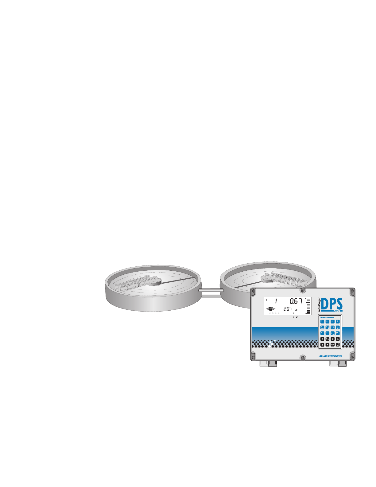
This microprocessor based level monitor is designed specifically for the
measurement of sludge blanket levels in wastewater clarifiers. A DPS300 level
monitor, and Siemens ultrasonic transducer, accurately monitor the sludge blanket
level without contacting the blanket.
The DPS300 transmits electrical pulses to the transducer. The transducer
converts the electrical pulses to ultrasonic pulses, which are emitted from the
transducer face. The DPS300 measures the time from pulse emission to reception
of the echo from the sludge interface. The time measured, is used to calculate the
distance from the transducer face to the sludge blanket.
The distance calculation is dependent upon the sound velocity through the
wastewater in the clarifier, which is in turn dependent upon the temperature of the
wastewater. The transducer, having an integral temperature sensor, and being
immersed into the wastewater, also monitors the temperature of the wastewater.
The transducer transmits the temperature to the DPS300, where velocity
compensation is applied to the level measurement calculation.
Nominally speaking, the DPS300 is capable of detecting down to 4% solids, in up
to 30m of turbid wastewater, and 0.2% solids in 5 m of clear wastewater.
This material and measurement range versatility is accomplished by using
Siemens patented Sonic Intelligence™. Sonic Intelligence provides high
measurement reliability, regardless of changing conditions in the clarifier.
InterRanger DPS300 10 7ML19981BC01

By using ultrasonic echo ranging principles with Sonic Intelligence and velocity
compensation, the DPS300 provides outstanding measurement accuracy, up to
1% of range, depending on process conditions.
The distance calculation may be converted to space, material level, material
volume, or remaining capacity. The Reading chosen (and operating data) for each
clarifier is displayed on the Liquid Crystal Display (LCD).
The relays and mA outputs may be used as preset (or programmed as desired) to
activate alarms and/or operate remote monitoring equipment and/or process
control equipment.
As well, the DPS300 may be connected to a Milltronics BIC-II (Buffered Interface
Converter) to provide RS-232 and/or RS-422 communications for host computers,
Distributed Control Systems, and special (capable of operating as a host device)
Programmable Logic Controllers.
Programming can be done locally using the portable programmer keypad, or
remotely through optional Dolphin software or SmartLinx
®
.
• The programmer transmits the keypad entries via infrared link to the DPS300, and
can be removed when not in use.
• Dolphin allows programming either through the portable ComVerter and infrared
link or hardwired via the RS-232/485 communication port.
• SmartLinx
®
provides protocol specific hardware and software for interface with
popular industrial communication systems.
7ML19981BC01 11 InterRanger DPS300
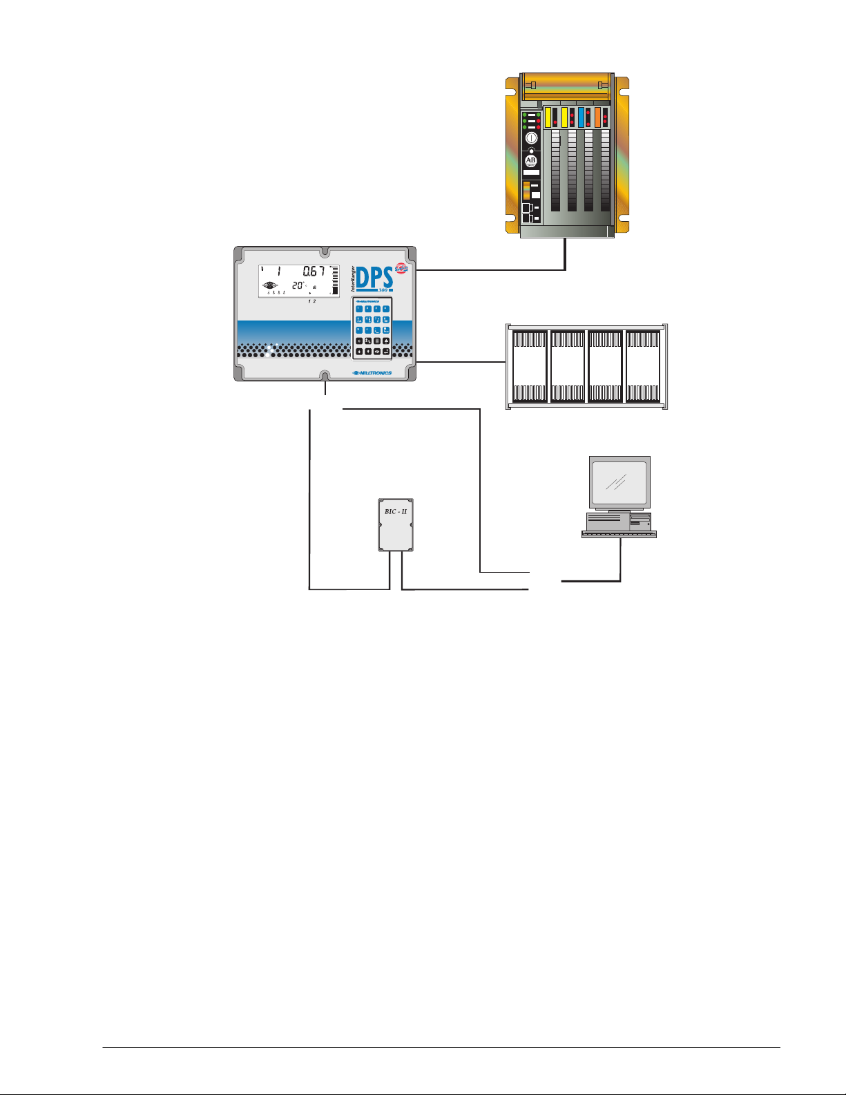
DPS300 Communication Overview
r
Plant-wide
control system
network
0/4—20mA
(PLC or DCS)
RS-232 or 485
(local)
or
SmartLinx®
Bipola
current loop
(remote)
RS-232 or 422
or
InterRanger DPS300 12 7ML19981BC01

Important InterRanger DPS300 Features
Fixed Features
Enclosure: Corrosion resistant, dust and liquid tight.
Backlit LCD: Large digits for Reading and programming value
displays.
Illuminated LCD insures readability under all lighting
conditions.
Custom Graphic Symbols for continuous indication of
operating conditions.
Programmer: 20 keys for easy access to programming and
operating functions.
Magnetic mounting and infrared interface permit
removal on programming completion.
Scanning: Capable of scanning two clarifiers, with the addition of
a second transducer.
Communications: SmartLinx® Compatible
Communications ready when equipped with an
appropriate Siemens SmartLinx module.
Milltronics Peripherals
The communication port provides connection for
RS-232, RS-485 or Milltronics bipolar current
loop. The current loop provides remote
communication via Milltronics BIC II to the
peripheral device. The BIC II converts the current
loop to RS-232 or RS-422 signal
Dolphin Compatible Communications
Dolphin Plus is Windows95®-compatible
software. It offers local interface through the
infrared ComVerter, or remote connection
through the RS-232 or RS-485 port. The software
provides an easy means for programming,
uploading, or downloading parameters.
Reliability: Sonic Intelligence™ ensures all measurements are
accurate and reliable.
Immune to power interruptions. All programming is
stored indefinitely. Dynamic operating data is retained
for one hour and updated immediately on power
resumption.
7ML19981BC01 13 InterRanger DPS300

Programmable Features
Typically, a very small percentage of the programmable features require operator
alteration. However, for demanding measurement requirements any operator
programmable feature may be adjusted as desired.
Following is a list of some of the features that make the DPS300 easy to program,
yet versatile enough to handle complex level measurement requirements.
General Features
Direct Access: Any operator programmable feature may be accessed
Scroll Access: Single button “scroll forward”, single button “scroll
Operation: Select “level”,”space”,or ”distance”.
Material: Select clarifier type; automatically adjusts echo
Units: Display Readings in m, cm, mm, ft, in, %, or any other
directly.
back”, to key features.
processing for the type of clarifier.
units desired.
Additional Features (Use as Desired)
Failsafe: Numerous failsafe options for process control
Relays: 8 functions including level, rate of change, pump
Fixed or independent on/off setpoints
mA outputs: Based on level, space, or distance.
4 range selections, 0-20, 4-20, 20-0, or 20-4 mA.
Adjustable range and over-range limits.
equipment activation.
control, temperature and more.
InterRanger DPS300 14 7ML19981BC01
As a System
s
d
y
r
As a system, the DPS300 is made up of:
minimum maximum
one DPS300 one DPS300
one XCT-12 transducer two XCT-12 transducers
one Skimmer Guard per transducer
one Mounting Assembly per transducer
one SmartLinx communications module
DPS300
mounting
plate
custome
conduit
Optional Siemen
Skimmer Guar
The Skimmer Guard
protects the transducer b
allowing it to ride over a
passing skimmer.
DPS300
Siemens Mounting Assembly
Mounts the transducer to
handrails along the clarifier
walkway or bridge.
Siemens XCT-12
The ultrasonic transducer used with the DPS300. If
the DPS300 is programmed to monitor two clarifiers,
then two transducers are required.
Note:
Operation of the transducer requires that the face be
immersed 3 to 6 cm into the clarifier wastewater.
DPS300 System Integration
• Assemble the transducer to the Siemens Skimmer Guard if provided. Otherwise
install directly to your conduit with a ¾” to 1” NPT or BSP reducer.
Refer to the Skimmer Guard section for dimension and assembly details. Refer to
the XCT-12 manual for connection and wiring details only.
• Assemble the Siemens Mounting Assembly, if provided, to the handrail. And,
mount the transducer (with Skimmer Guard if provided) to the Mounting Assembly.
Otherwise mount the transducer assembly in a secure fashion.
Refer to the Mounting Assembly section for dimensions and assembly details.
• Install the DPS300 and program the unit for your specific application.
Refer to the Application and Parameters sections of this manual.
7ML19981BC01 15 InterRanger DPS300

The DPS300 is designed to detect and measure the sludge blanket in up to two
wastewater clarifiers. The basic requirements of a working DPS system are the
transducers and the associated electronics.
The electronics can be mounted at the clarifier or up to 365 m away from the
transducer. Refer to DPS300 Specifications in this manual.
The transducer is installed such that its face is immersed 3 to 6 cm in the clarifier
wastewater.
Beyond these given requirements, a few practical aspects of the clarifier
application and its operation are of particular concern.
Circular Clarifiers
There are several different types of circular clarifiers, but all operate in the same
basic way and share common design features that will need to be considered
when installing an InterRanger™ DPS300.
Some of these considerations are:
APPLICATION PLANNING
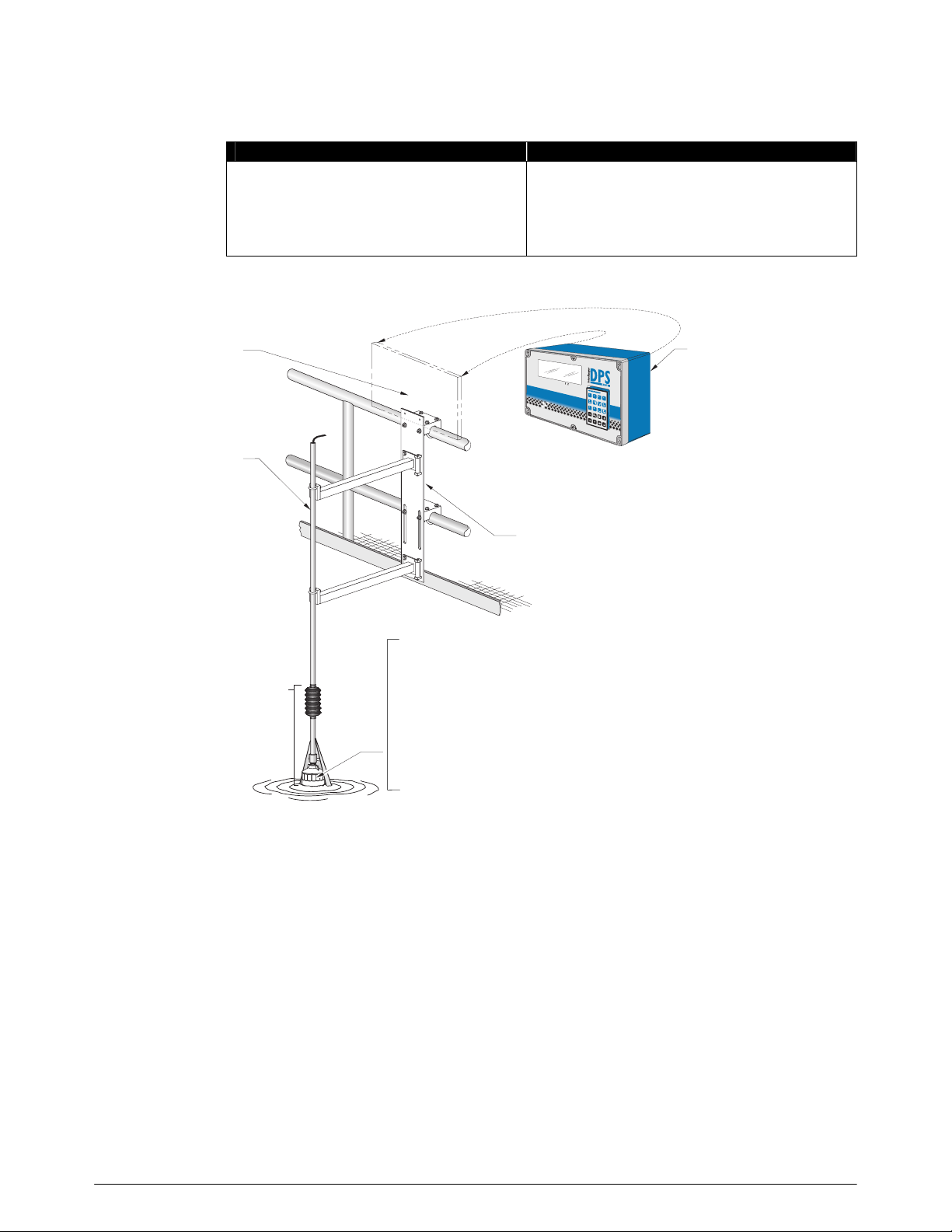
Catwalk, Bridge or Walkway
Most circular tanks have a catwalk that extends into the centre of the tank, usually
with 2" (51 mm) or similar, tubular railings. These railings are the recommended
mounting location for the InterRanger™.
The Siemens Mounting Assembly is available to locate the transducer in this
location.
Inlet
This is where the wastewater flows into the tank. Do not mount the transducer
close to the inlet because the water is aerated and the sludge is disturbed. To
obtain the most accurate readings, the sensor should be located above a relatively
undisturbed portion of the tank where aeration is not present.
Tank sides
The sensor must be mounted at least 1 m (3') from the side of the tank. If the
sensor is mounted closer than this the walls could cause interference and
ultimately lead to inaccurate signals or errors.
Ladders, Beams, Supports, etc.
Be sure that there are no permanent underwater obstructions within 1 m (3') of the
sensor that could disrupt the signal. Obtain drawings and/or consult with plant
personnel to locate any of these structures that may not be visible.
InterRanger DPS300 16 7ML19981BC01
Surface Skimmers
Skimmers are used to remove the scum from the surface of the water in the
clarifier. The scum is skimmed away from the effluent weirs into a trough where it
can be removed easily.
It is important to observe the skimmer action when setting up the InterRanger. If
the best location for the sensor is in the path of the skimmer (often the case) then
the optional Skimmer Guard must be used.
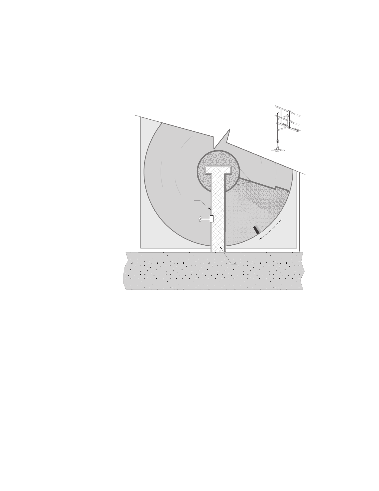
Circular Clarifier
skimmer
handrail
scum trough
mounting
location
bridge
skimmer
direction
Scrapers
Scrapers keep the oldest sludge on the bottom of the tank from hardening and
help to move the sludge into a hopper for pumping.
In circular tanks, the skimmer and scraper are often connected to the same
rotating mechanism radiating from the centre of the tank. Common configurations
could include one or two skimmers and up to four scrapers. Usually these arms
are 90° or 180° apart.
7ML19981BC01 17 InterRanger DPS300

Moving or Travelling Bridges
mounting
location
handrail
bridge
travelling bridge
direction
On some clarifiers the bridge or walkway moves with the skimmer. For clarifiers
with these types of arrangements, care must be taken when choosing a mounting
location. The following items should be considered when choosing a location on
the bridge:
• The transducer should be mounted in front of the bottom scraper mechanism.
The sludge becomes very disturbed after the passing of a bottom scraper and a
clean interface will be difficult to detect. Mount the transducer in front of the
scraper, ideally 180° from the scraper or 90° if two scrapers exist.
• Ensure that the transducer will not come into contact with the scum trough.
It is important to observe the bridge motion through at least one complete cycle to
ensure that the transducer and/or the mounting assembly will not collide with any
structures in the tank.
Rectangular Clarifiers
There are several different types of rectangular clarifiers, but all operate in the
same basic way and share common design features that will need to be
considered when installing an InterRanger™ DPS300.
Some of the considerations are:
Catwalk, Bridge or Walkway
Some rectangular tanks have a bridge that spans across the entire width of the
tank, usually with 2" (51 mm) or similar, tubular railings. These railings are the
recommended mounting location for the InterRanger™ once a suitable spot has
been found.
The Siemens Mounting Assembly is available to secure the transducer in this
location.
InterRanger DPS300 18 7ML19981BC01

Inlet
r
This is where the wastewater flows into the tank. Do not mount the transducer
close to the inlet because the water is aerated and the sludge is disturbed. To
obtain the most accurate readings, the sensor should be located above a relatively
undisturbed portion of the tank where aeration is not present.
Tank sides
The sensor must be mounted at least 1 m (3') from the side of the tank. If the
sensor is mounted closer than this, the walls could cause interference and
ultimately lead to inaccurate signals or errors.
Ladders, Beams, Supports, etc.
Be sure that there are no underwater obstructions within 1m (3') of the sensor that
could disrupt the signal. Obtain drawings and/or consult with plant personnel to
locate any of these structures that may not be visible.
Surface Skimmers
Skimmers are used to remove the scum from the surface of the water in the
clarifier. They are usually short fences called “flights” that are pulled along the top
of the water with a chain mechanism in rectangular tanks. The scum is skimmed
away from the effluent weirs into a trough where it can be removed easily. It is
important to observe the skimmer action when setting up the InterRanger. If the
best location for the sensor is in the path of the skimmer then the optional
Skimmer Guard must be used.
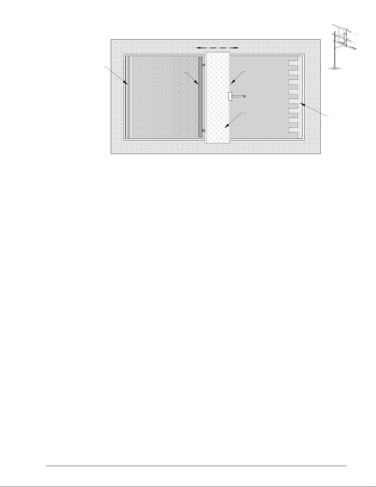
Rectangular Clarifier
scum
trough
Scrapers
Scrapers keep the oldest sludge on the bottom of the tank from hardening and
help to move the sludge into a hopper for pumping. In rectangular tanks, often the
scrapers are also the skimmers. They run along the bottom on a chain mechanism
for the length of the tank, up the side and then along the top to pull the scum into a
trough.
skimmer direction
mounting location
flights
handrail
effluent
wei
7ML19981BC01 19 InterRanger DPS300
Moving or Travelling Bridges
r
scum
trough
skimme
bridge movement
handrail
mounting
location
travelling
bridge
effluent
weir
For clarifiers with these types of arrangements, care must be taken in choosing a
mounting location. The following items should be considered when choosing a
location on the bridge:
• The transducer should be mounted behind (after) the surface skimmer (if present).
This is to help minimize the amount of potential scum build-up on the transducer.
• The transducer should be mounted in front of the bottom scraper mechanism.
The sludge becomes very disturbed after the passing of a bottom scraper and a
clean interface will be difficult to detect. Mount the transducer in front of the
scraper, not behind.
• The transducer should not be mounted near any siphoning-type outlet.
Some clarifiers utilize a siphoning technique to maintain sludge levels. Do not
locate the transducer near these outlets as the sludge is more disturbed there.
Location
• Ensure the transducer will not come into contact with effluent weirs or scum
troughs at either end of the bridge travel.
It is important to observe the bridge motion through at least one complete cycle to
ensure that the transducer and/or the mounting assembly will not collide with any
structures in the tank.
An average sludge level reading will be displayed for the location at which the
transducer is installed. This location may have to be compromised for practical
reasons, pertaining to the physical installation of the transducer, and physical or
operational characteristics of the clarifier.
We suggest these examples:
Skimmers
Where surface skimmers are in use, the optional Skimmer Guard should be used
to protect the transducer and from passing skimmers.
InterRanger DPS300 20 7ML19981BC01

Mounting
If the Skimmer Guard is required, it can be field installed in a manner suitable for
the clarifier installation and its surroundings. Consult with your mechanical
department or contractor.
The Mounting Assembly provides a method of installing the transducer or
Skimmer Guard to clarifier handrails.
As mentioned, mounting of the transducer must take into account several
considerations.
• vertical adjustment of the transducer so that it is immersed in the clarifier water 3
to 6 cm.
Siemens Mounting Assembly provides this.
• horizontal adjustment of the transducer so that it can be extended away from the
clarifier wall or handrail
Siemens Mounting Assembly provides this.
• articulation of the transducer conduit so that, where skimmers are in use, the
transducer is deflected out of the way as the skimmer passes.
Siemens Skimmer Guard provides this.
7ML19981BC01 21 InterRanger DPS300
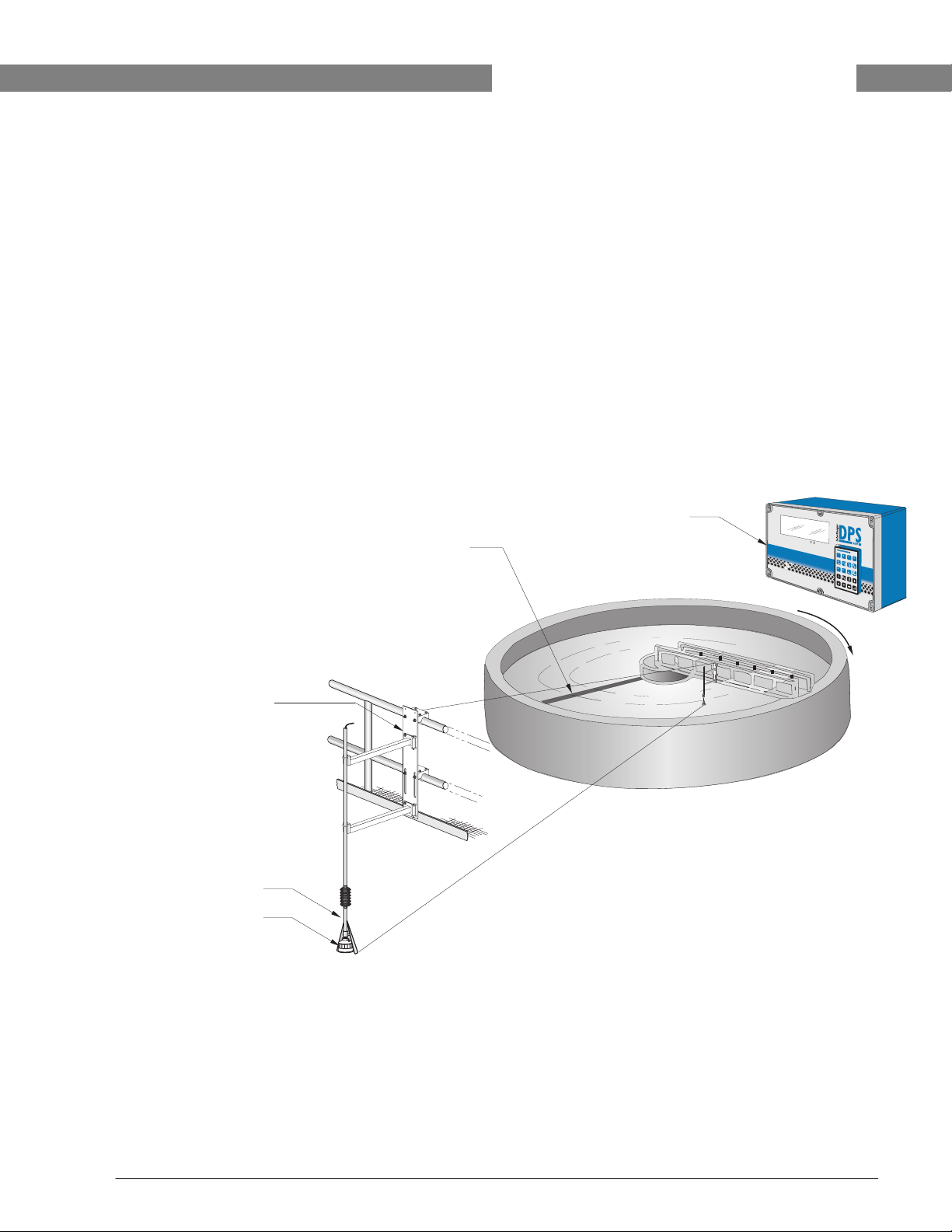
APPLICATION EXAMPLE
y
r
r
r
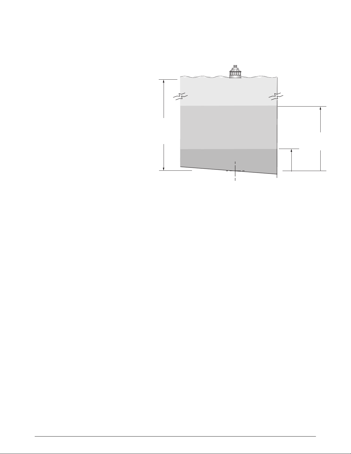
It is desired to measure the sludge blanket in a circular primary clarifier. The
clarifier is equipped with a skimmer, and the depth of wastewater in the clarifier is
approximately 5 m. When the sludge level rises to about 0.3 m, a pump turns on
to pump out the sludge to a level of about 0.1 m. The pump is then turned off.
Set the following parameters as follows:
System requirements:
• one DPS300*
• one XCT-12 transducer
• one Siemens Skimmer Guard
• one Siemens Mounting Assembly
*The DPS300 is a dual point monitor, capable of measuring two clarifiers when the
unit is equipped with two transducers. This example shows the unit used for single
point monitoring but two could be used.
DPS300
Milltronics
Mounting
Assembl
Milltronics Skimme
Guard
XCT-12
transduce
skimme
skimmer
travel
The DPS300 can be
mounted locally on the
clarifier or remotely in a
control room.
Note:
When powered up, the DPS300 will take up to several minutes to lock onto its first
measurement. During this time several errors may be reported. These errors
should be ignored. If errors are reported after the startup period, consult the
Troubleshooting section.
InterRanger DPS300 22 7ML19981BC01
P001 = 1
P002 = 1
P005 = 1
P006 = 4.9,
P110, relay 1 = 1
P111, relay 1 = 50,
sludge level measured from bottom (see P006)
primary clarifier
units in meters
distance from the face
of the transducer to the
bottom of the clarifier
directly beneath
P006 =
4.9 m
relay 1 is assigned to
point 1
P112 =0.3 m,
pump on
P112 =0.1 m,
pump off
relay 1 is assigned for pump control
P112, relay A setpoint = 0.3
sludge level at which the pump turns on
P113, relay B setpoint = 0.1
sludge level at which the pump turns off
7ML19981BC01 23 InterRanger DPS300

Location
Electronics
INSTALLATION
Note:
Installation shall only be performed by qualified personnel, and in accordance with
local governing regulations.
Although the Mounting Assembly provides a mounting plate for external
installation, the unit can also be installed indoors in a controlled environment
comfortable to operating personnel.
If it is required to mount the unit outdoors, the supplied panel can be attached to
the Mounting Assembly.
Regardless, the unit must be mounted in an area that:
• is conformant to the units specifications
• provides clearance to swing open the front cover and perform the required wiring
connections
• provides access for viewing
• is vibration free
Avoid a location that is:
exposed to continuous direct sunlight. (Otherwise, provide a sun shield.)
close to high voltage or current runs, contactors, or SCR control drives
Cable/Conduit Entry Requirements
Determine the number of conduit entries required:
• transducer(s) – one or two transducers
• communications – SmartLinx, RS-485, RS-232, bi-polar
• instrumentation – relay outputs, 4-20 mA
• synchronization – if more than one unit in proximity
• power
Note:
• Transducer cables must be run in a grounded metal conduit, separate from
other wiring, (except TS-3 temperature sensor wiring, if applicable).
• This product is susceptable to electrostatic shock. Follow proper grounding
procedures.
InterRanger DPS300 24 7ML19981BC01
Transducer
As the transducer represents the point of measurement of the sludge blanket, it
should be located where it can give a reliable and meaningful measurement.
The ideal location may be compromised due to structural considerations of the
clarifier, and practicality of installation. Refer to Application Planning on page 16
for more information.
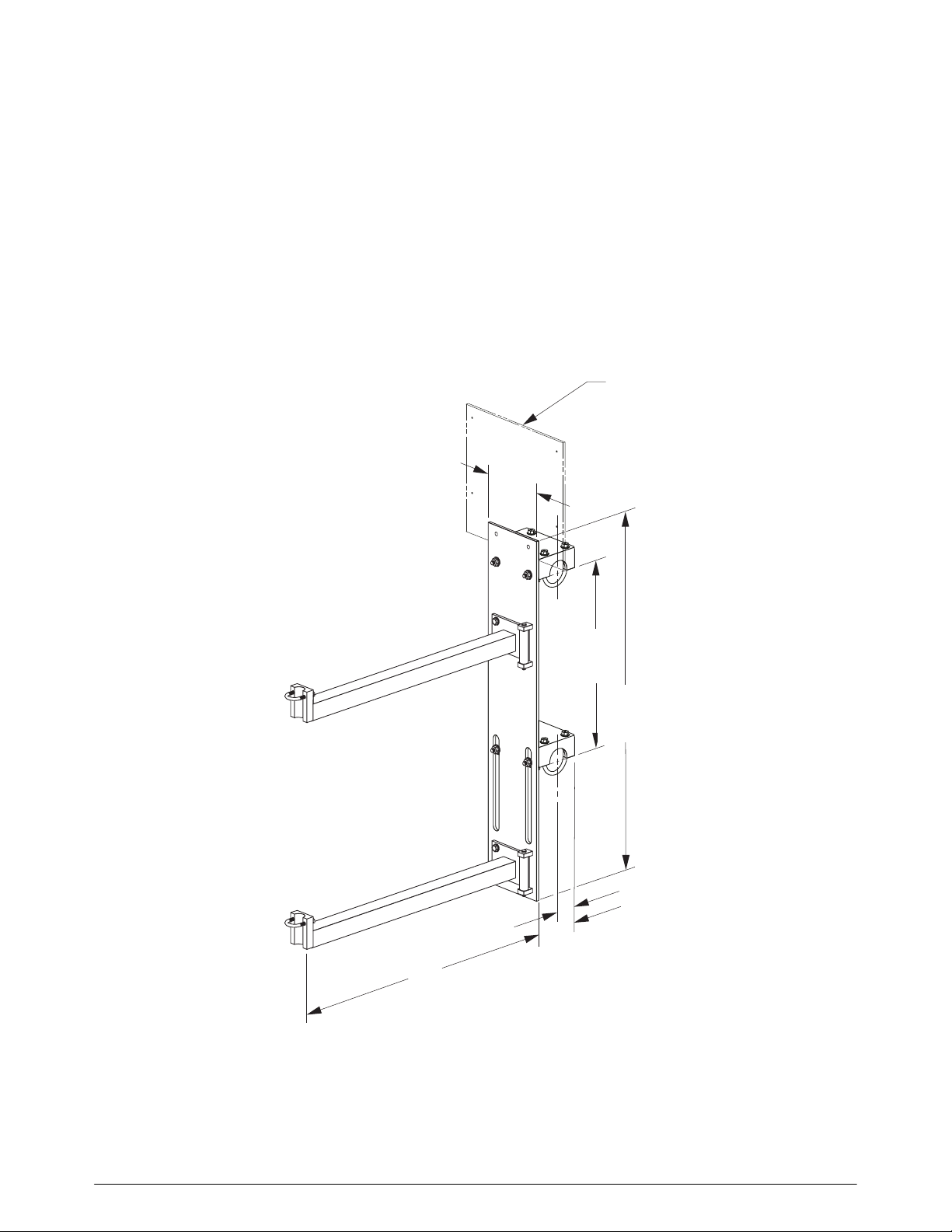
Optional Mounting Assembly
The mounting assembly provides an easy means of extending the transducer out
into the clarifier wastewater by hanging off of nearby handrails.
305 w x 292 h mm
(12 w x 11. 5 h ”)
432 to
610 mm
(17–24”)
826 mm
(32.5”)
7ML19981BC01 25 InterRanger DPS300
Mounting Assembly Usage
In clarifiers where skimmers are in use, the transducer must be raised to avoid
damage from the passing skimmer. If you have a Siemens Skimmer Guard, refer
to that manual before installing the Mounting Assembly.
Refer to the DPS300 system manual to determine the appropriate location for
installing the Mounting Assembly.
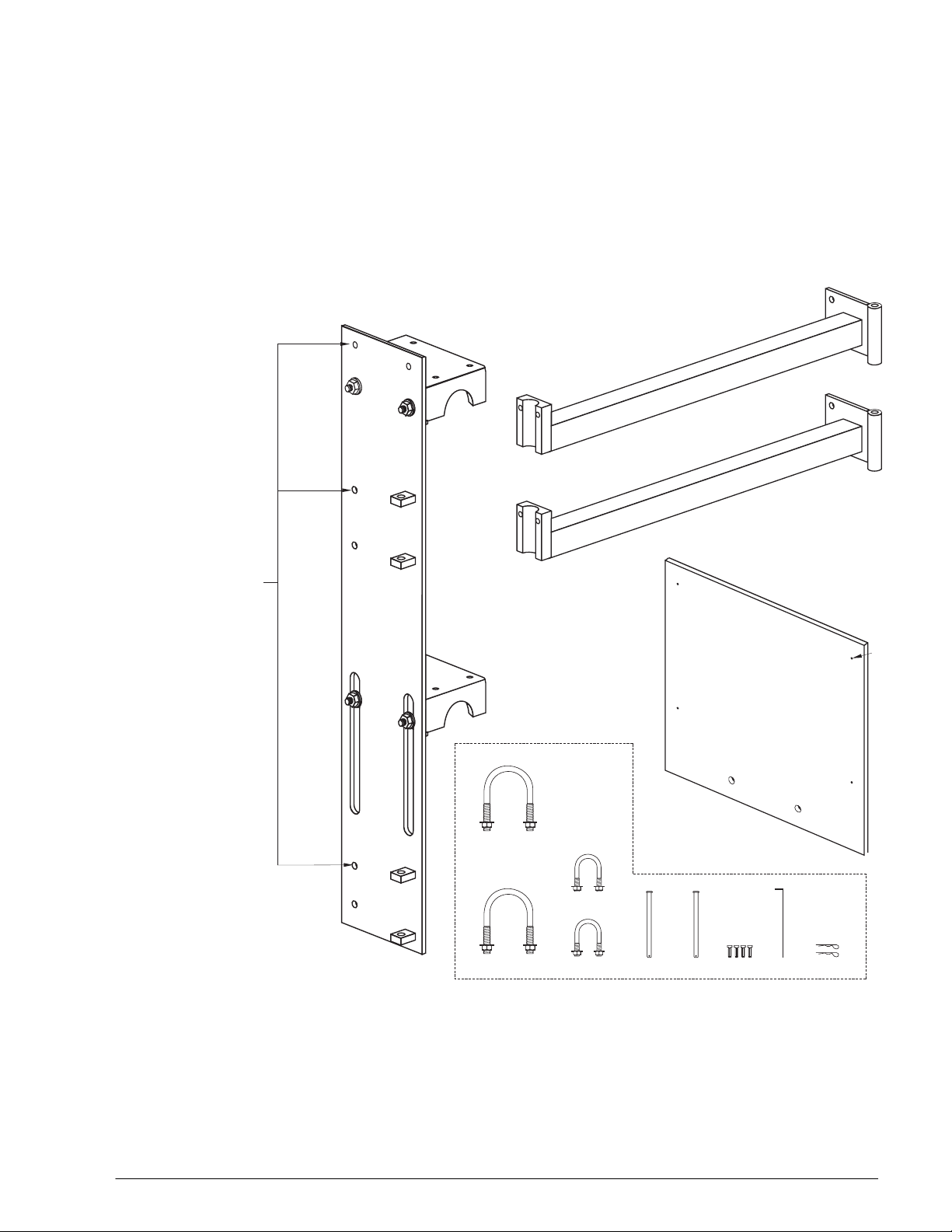
Components
rail bracket (2)
extension arms (2)
5/16 – 18 x 1 bolt
2 washers (flat)
1 lock nut
(in hardware bag)
base plate (1)
u-bolts
(with nuts & washers)
(4 large & 2 small)
clevis pin (2)
in hardware bag
mounting plate (1)
(for DPS300 electronics)
6-32
hex
bolts
(4)
hitch pin (2)
7/64”
hex
key
6 – 32
threaded
hex bolts in
hardware
bag.
InterRanger DPS300 26 7ML19981BC01
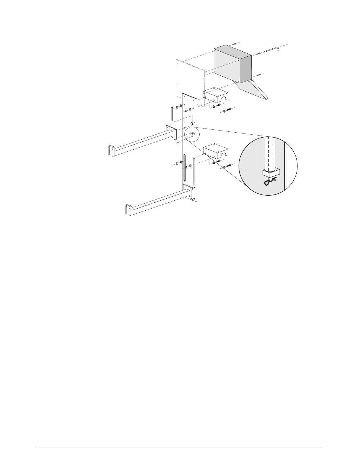
Assembling the Mounting Assembly
4.
1.
2.
1.
3.
2.
Assemble the rail brackets, upper and lower, to the base plate
Assemble the extension arms, upper and lower, to the base plate by mating the arm
and plate hinges and inserting the hinge pins.
Secure each hinge pin by inserting a hitch pin through the hole at the end of the pin.
(Optional) If it is required to mount the DPS300 at the clarifier, then attach the
mounting panel to the base plate. Use the hex bolts provided to mount the
DPS300 to the mounting panel. The DPS300 is pre-drilled with the appropriate
holes.
7ML19981BC01 27 InterRanger DPS300
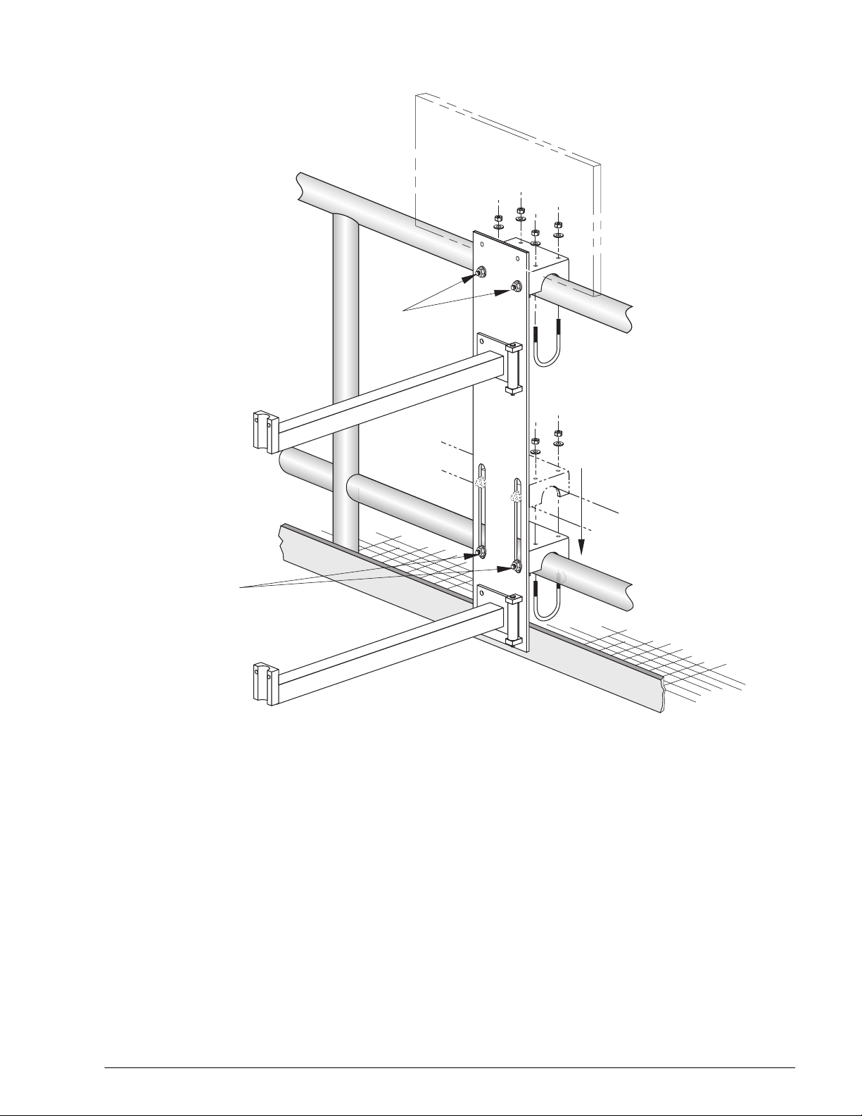
Mounting Assembly Installation
slip bolts
2.
1.
4.
3.
1.
4.
1. Attach the Mounting Assembly to the clarifier handrail by hanging the upper and lower rail brackets
from the upper and lower rails.
2. The upper rail bracket is fixed. Check that the bolts are securely fastened.
3. Slide the lower rail bracket in position so that it rests on the lower rail. Tighten the slip bolts to
secure the bracket.
4. Insert the four larger u-bolts through the upper and lower brackets, clamping the brackets to the
rails and fasten with the supplied washers and nuts.
InterRanger DPS300 28 7ML19981BC01
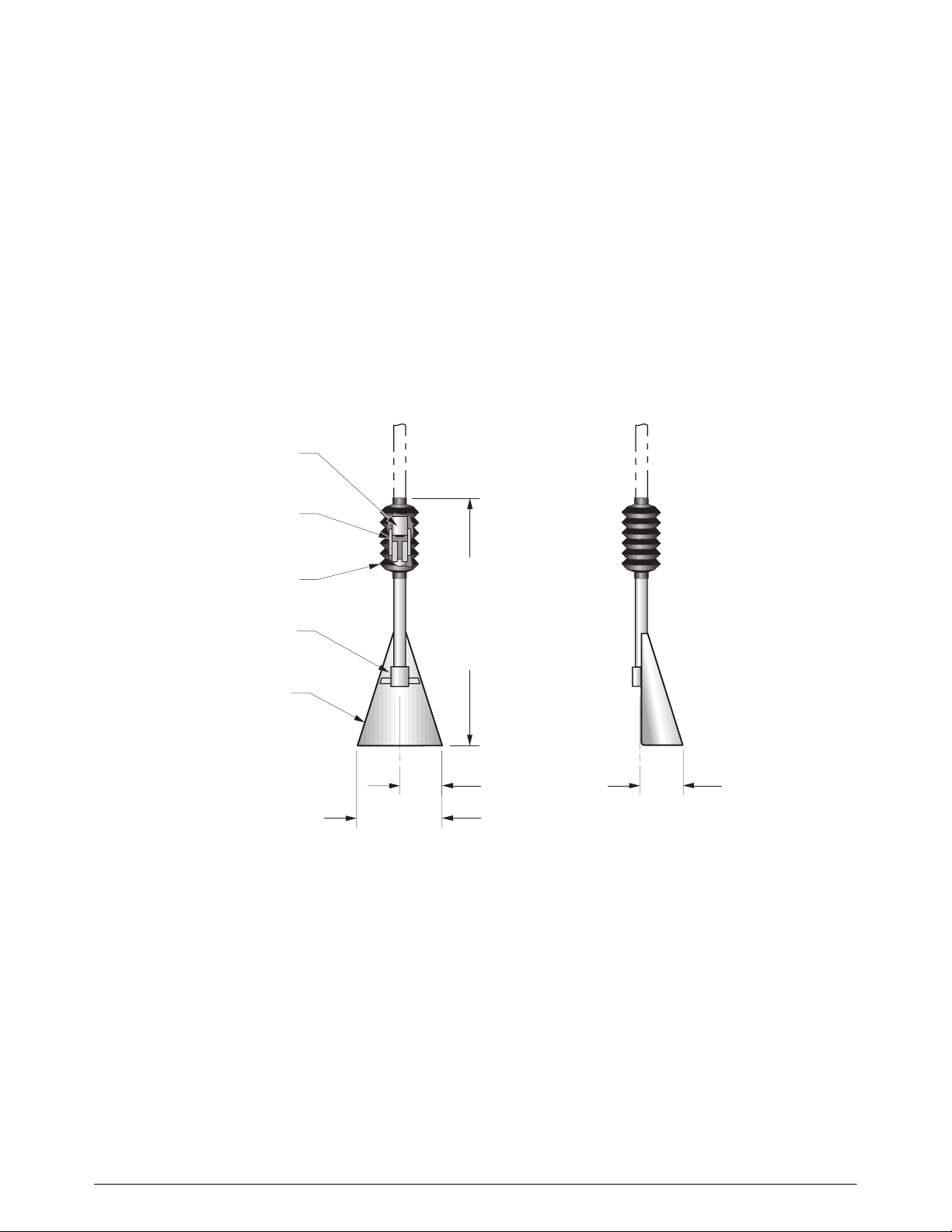
Optional Skimmer Guard
The skimmer guard is designed for use with transducers applied to measurement
of sludge in wastewater clarifiers. The guard provides articulation of the
mechanical and electrical conduit connection to the transducer where skimmers
are in use.
As the skimmer passes, it contacts the skimmer guard and pushes it up and over
the skimmer; effectively clearing the transducer out of harm’s way. Once the
skimmer has passed, the guard is free to fall, re-immersing the transducer into the
clarifier water.
The skimmer guard is available in two sizes:
• Type A – for skimmers 20 cm (8”) or less in cross-sectional height
• Type B – for skimmers 40 cm (16”) or greater in cross-sectional height
conduit coupling,
¾” NPT or BSP
hinge
boot
transducer coupling,
1” NPT or BSP
guard
200 mm
(8”)
Type A:
500 mm (20”)
Type B:
890 mm (35”)
100 mm
(4”)
97 mm
(3.8”)
7ML19981BC01 29 InterRanger DPS300
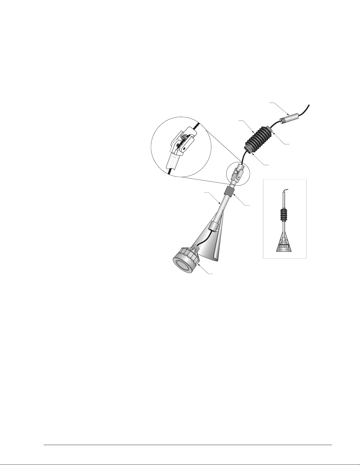
Transducer Assembly
5. Procure a length of corrosion resistant conduit for suspending the transducer and skimmer guard
assembly such that the transducer face will be immersed 3 to 6 cm into the clarifier water.
Siemens suggests ¾” standard stainless steel pipe (schedule 10) cut with ¾” NTP threads.
6. To facilitate running the transducer cable through the conduit, fish a wire through from the hinge
end first.
7. Slide the 2-inch hose clamp over the
knuckle of the Skimmer Guard.
customer conduit
8. Run the transducer cable through the
skimmer guard; starting at the
transducer coupling, through the
conduit and out the hinge.
9. Pull the cable through until the
transducer is pulled up to the
mounting coupling.
10. Screw the transducer into the
mounting coupling and tighten.
skimmer guard
11. Run the transducer cable from the hinge out the conduit
coupling.
12. Pull cable taught insuring that the cable will not
get pinched in the hinge.
13. Run the transducer cable through the
boot and customer conduit.
14. Slide the boot over the end of the customer
conduit, and screw the conduit into the coupling.
boot
1” hose clamp
2” hose clamp
2”
bushing
transducer
15. Slide the boot over the hinge.
The transducer and skimmer guard are now ready for installation.
Location and Installation
If a Mounting Assembly is used …
If a Siemens mounting assembly is being used to mount the Skimmer Guard
assembly, first refer to Optional Mounting Assembly on page 25.
For Location
For recommendations as to the preferred point of installation of the transducer and
skimmer guard, refer to Application Planning on page 16.
InterRanger DPS300 30 7ML19981BC01
 Loading...