

Siemens Insys 56k Operating Manual
Operating Manual
Pocket Modem 56k
December 05

Copyright © INSYS MICROELECTRONICS GmbH
Any duplication of this manual is prohibited. All rights on this documentation
and the devices are with INSYS MICROELECTRONICS GmbH Regensburg.
Restrictions of guarantee
This handbook contains a concise description. The compilation of the text has
been made with the utmost care. Despite all efforts, there may be deviations
compared with the actual functions. No guarantee can therefore be given for
the accuracy of the contents. We can neither take over a legal responsibility nor
any liability for incorrect information and their consequences. Suggestions for
improvements and comments are gladly accepted.
Trademarks
The use of a trademark not shown below is not an indication that it is freely
available for use.
MNP is a registered trademark of Microcom Inc.
IBM PC, AT, XT are registered trademarks of International Business Machine Corporation.
INSYS ® is a registered trademark of INSYS MICROELECTRONICS GmbH.
Windows™ is a registered trademark of Microsoft Corporation.
Publisher:
INSYS MICROELECTRONICS GmbH
Waffnergasse 8
D-93047 Regensburg, Germany
Phone: +49 (0)941/58692-0
Fax: +49 (0)941/563471
e-mail: insys@insys-tec.de
Internet: http://www.insys-tec.de
Subject to technical changes as well as correction.
Date: December 05
31-22-06.010 - english

Pocket Modem 56k Content
Dezember 05 I
1 SCOPE OF DELIVERY....................................................1
2 GENERAL.....................................................................1
3 NOTES REGARDING THE USE OF THE MANUAL..........2
4 MOUNTING ................................................................3
4.1 FRONT PANEL ............................................................................3
4.2 BACK PANEL..............................................................................3
4.3 INSTALLATION INSTRUCTIONS.......................................................4
5 FUNCTIONS.................................................................5
5.1 CONFIGURATION .......................................................................5
5.1.1 Change Configuration ........................................................................5
5.1.2 Save Configuration .............................................................................7
5.2 SERIAL DATA TRANSMISSION .......................................................7
5.2.1 Automatic Baud Rate Detection.........................................................7
5.2.2 Data Buffer for Serial Data Transmission...........................................8
5.2.3 Bit Direct Mode ...................................................................................8
5.2.4 Hardware Data Flow Control with RTS/CTS .......................................8
5.2.5 Hardware Data Flow Control with the PC (RTS) .................................9
5.2.6 Software Data Flow Control XON and XOFF ......................................9
5.2.7 Reset..................................................................................................10
5.2.8 Dial-up Delay ....................................................................................10
5.3 ERROR CORRECTION .................................................................10
5.3.1 V42 Error Correction .........................................................................10
5.3.2 MNP 2/3/4 Error Correction..............................................................11

Content Pocket Modem 56k
II Dezember 05
5.4 DATA COMPRESSION ................................................................11
5.4.1 V.42bis Data Compression................................................................11
5.4.2 MNP 5 Data Compression .................................................................12
5.4.3 V.44 Data Compression ....................................................................12
5.5 SELECTIVE CALL ANSWER...........................................................13
5.6 SEND MESSAGES .....................................................................15
5.6.1 Transmission Configuration .............................................................15
5.6.2 Triggering..........................................................................................16
5.6.3 Fax Logging.......................................................................................16
5.7 REMOTE CONFIGURATION (REMOTE CONTROL).............................17
5.7.1 Mode of Operation ...........................................................................17
5.7.2 Remote Modem Preparation ............................................................17
5.7.3 Change Default Password at Remote Modem .................................17
5.7.4 Local Modem Operation ...................................................................18
5.7.5 Reduced Command Set.....................................................................18
5.7.6 Terminate the Remote Configuration Process.................................18
5.8 ACCESS CONTROL ....................................................................19
5.8.1 Password ...........................................................................................19
5.8.2 Data Connection ...............................................................................19
5.8.3 Security Callback...............................................................................19
5.8.3.1 Preparation..........................................................................................................19
5.8.3.2 Operation............................................................................................................. 20
5.9 DATA TRANSMIT CONTROLLER (IDLE CONNECTION CONTROL)..........21
5.9.1 Activation..........................................................................................21
5.9.2 Mode of Operation for the “Timer” .................................................21
5.10 PRIORITY CIRCUIT FOR MODEMS WITH PHONES
C
ONNECTED IN SERIES ..............................................................22
5.10.1 Detecting a Busy Phone Line ............................................................22
5.10.2 Going Off-hook on Account of a Telephone Connected in Series....23
5.10.3 Remote Terminal Connection Abort.................................................24

Pocket Modem 56k Content
Dezember 05 III
6 UPDATE ..................................................................25
6.1 FLASHCOM.EXE .......................................................................25
6.2 TERMINAL PROGRAM................................................................26
6.2.1 Requirement .....................................................................................26
6.2.2 Activation and Process......................................................................26
7 AT COMMANDS........................................................28
7.1 OVERVIEW AT COMMANDS.......................................................28
7.2 OVERVIEW FAX AND VOICE COMMANDS .....................................52
7.3 AT MESSAGES.........................................................................52
8 S REGISTRY ...............................................................55
8.1 SOVERVIEW S REGISTRY............................................................55
8.2 DESCRIPTION S REGISTRY ..........................................................56
9 OVERVIEW FOR THE SENDING OF SMS AS FAX OR E-
MAIL .........................................................................65
9.1 SMS AS FAX ...........................................................................65
9.2 SMS AS E-MAIL ......................................................................66
10 FAQ...........................................................................67
11 SAFETY INSTRUCTIONS......................................69
11.1 GENERAL................................................................................69
11.2 SMS .....................................................................................69
11.3 CLEANING...............................................................................69

Content Pocket Modem 56k
IV Dezember 05
12 TECHNICAL DATA......................................................70
12.1 PHYSICAL FEATURES .................................................................70
12.2 SERIAL INTERFACE ....................................................................70
12.3 INTERFACE SPEEDS....................................................................71
12.4 SUPPORTED STANDARDS...........................................................71
12.5 PHONE INTERFACE....................................................................72
12.6 ITU STANDARDS (CCITT)..........................................................73
13 COUNTRY CODES......................................................74
14 DECLARATION OF CONFORMITY ..............................77

Pocket Modem 56k Scope of Delivery
Dezember 05 1
1 Scope Of Delivery
Before you begin with the initial operation, please check if all accessories are
included in the box.
¾ INSYS Modem 336 or INSYS Modem 56k
¾ Phone cord (TAE-N to RJ11)
¾ PC connection cable 9/9-pin (RS232 cable)
¾ User Guide
¾ CD-ROM (optional)
In case the content is not complete, please refer to your supplier. Please also check
the modem for shipping damage. Please also refer to your supplier if damage
exists.
Please keep the packaging material for possible future dispatch or storage.
2 General
The Pocket Modem 56k is a modem for the analog telephone network. It has a
very compact design and a very robust aluminum housing. The modem supports
the following functions, which are described in detail in the following:
¾ Establishing a data connection
¾ Automatic call
¾ Alarm inputs and outputs for SMS dispatch and to establish an alarm data
connection
¾ Pulse input to send up to 10 SMS messages
¾ Fax dispatch at alarm release
¾ Local or remote configuration
¾ Usage in 87 countries
¾ Auto answer
¾ Data flow control
¾ Data compression
¾ Error correction
¾ Idle connection control
¾ Flash update
¾ Security callback

Notes Regarding the Use of the Manual Pocket Modem 56k
Dezember 05 2
3 Notes Regarding the Use of the Manual
¾ This manual uses the symbol for especially important notes. Further
notes will be marked accordingly.
¾ All factory settings are marked with “default”.
Example (Chap. 5.7.3): Enter old password (default: QWERTY)
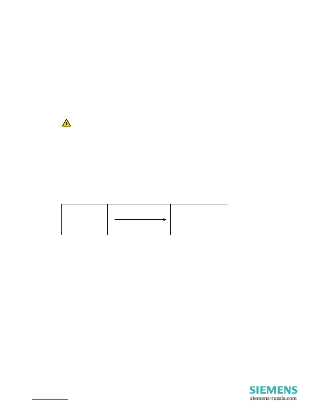
¾ In the Chapters 4 to 6, the description consists of two columns. On the left
side, the individual functions are described. The according AT commands
and the modem responses can be found in the right column.
Function description AT command
Example (Chap. 5.2.7):
After the hardware reset, load the user profile 1 ATZ1
¾ All AT commands start with the letters AT and end with a “Return”
(Carriage Return - CR). AT commands can be entered in capital or small
letters. The command is evaluated as soon as the modem received a
return.
¾ In the following, the used syntax is explained:
• ATDT AT command (font: Courier, bold)
• <Expression> Input of a parameter (font: Courier, bold)
• [Expression] Input of an optional parameter
(Font: Courier, bold)
• Expression Response from the modem (font: italic)
Examples:
• ATDT<n> Dialing of the phone number <n>
ATDT1234 Dialing of the phone number 1234
•+• AT+MS=<Modulation>, [Automode] Selection of the modulation
type
AT+MS=V92 Selection of the modulation
type V.92
AT+MS=V92,1 Selection of the modulation
type V.92 with automatic
adjustment
• Connect The connection to the remote terminal is
established
> Input prompt during the
remote configuration.
Pocket Modem 56k Mounting
Dezember 05 3
4 Mounting
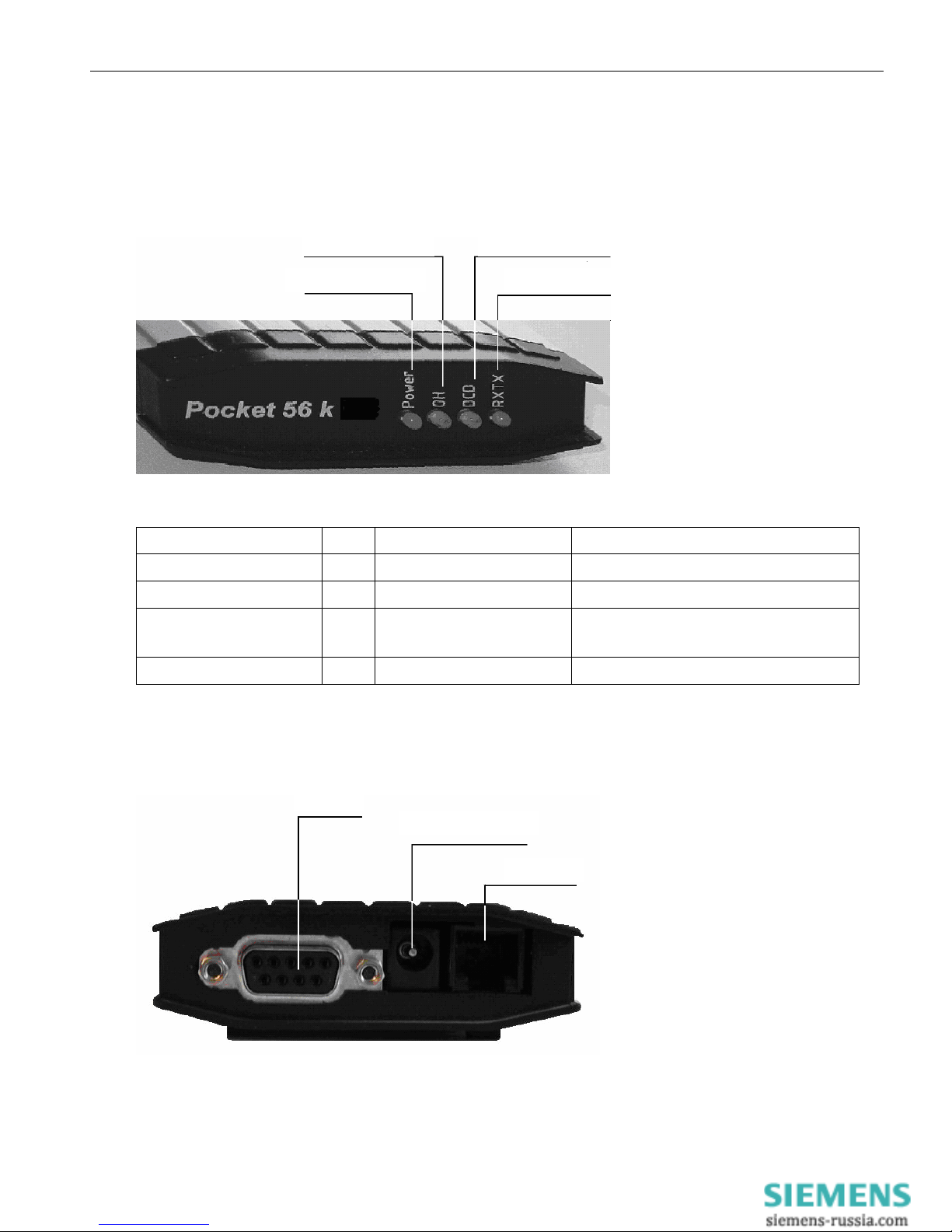
4.1 Front panel
Meaning Color LED off LED on
Power Green No supply voltage Supply voltage available
OH (Off Hook) Yellow Modem is offline Modem uses phone line (online)
DCD (Data Carrier Detect) Yellow No connection is established Connection to remote terminal is
established
RX/TX (receive/transmit) Green No data exchange Exchange of data via the modem
4.2 Back panel
Phone line
Power supply
Data line
Data exchange
RS 232
Power Supply
Phone

Mounting Pocket Modem 56k
4 Dezember 05
4.3 Installation Instructions
Please observe our safety instructions.
1 Switch on power supply
2 Connection with the PC
Connect the 9-pin jack at the modem with the serial
interface of your computer.
3 Driver Installation
If you use a terminal program or the HSComm program, the
installation of a driver is not necessary. If you use another
application, a driver may be necessary. Please find our
current drivers at http://www.insys-tec.de or install the
windows standard modem 336.
4 Modem communication
Now, start your communication program on the PC and set it
to the used COM interface. The modem will automatically
adjust to the baud rate of your PC.
5 Communication Control via a Terminal Program
Perform a short test using your terminal program
(TeraTermPro, ProcommPlus).
Check if the installation was successful
Enter the command and push the “Enter” key.
When the message appears on your monitor, the device
has been successfully installed.
6 Connection with the telephone network
Plug the supplied phone cord into the jack on the rear of
the modem. The plug of the cable must lock in.
The other end of the phone cord is plugged into the
telephone outlet. When modems are connected to older
phone outlets, an adapter or a multiple TAE/N outlet may
be necessary.
7 Check the connection between two modems
Enter the command and push the “Enter” key
Attention: For PBXs that require a code number to
establish a connection – the code number
is usually “0”- a different command must
be used.
The modem will be connect.
Power LED on
AT
LED RXTX on
OK
ATDT 0101901929
ATX3DT 0101901929
LED OH on
Connect…
LED DCD on

Pocket Modem 56k Function
Dezember 05 5
5 Functions
5.1 Configuration
5.1.1 Change Configuration
The modem offers a choice of profiles.
¾ Default factory setting:
The default factory settings enable you to achieve a
fixed defined basic state of the modem. Starting with
this “basis”, you can customize the modem according
to your requirements.
¾ User profiles 0 and 1:
You can save configurations in the user profile, which
may be re-used for certain purposes.
A part of the S registry is saved in each profile. In the
description, the affected registries are marked with an
“*” in the S registry (Chapter 9.2).
A part of the S registry is saved in each profile. In the
description, the affected registries are marked with an “*” in
the S registry.
Loading the factory settings into the active profile will enable
you to easily recover an executable state.
Loading the user profile 0
Loading the user profile 1
Prior to the loading of the user profile, a reset is performed.
The settings of all profiles can be displayed in an overview.
AT&F
ATZ0 ATZ
ATZ1
AT&V

Function Pocket Modem 56k
6 Dezember 05
Example:
The active profile will show all settings currently used by the
modem.
ACTIVE PROFILE:
B3 E1 L1 M1 Q0 T V1 W0 X4 *A1 *L0 *M0 *P0 *R1 *Y0,0 *Y1,0
%B0 %C3 %E2 %S0
\A1 \D0 \N3 \V0 &A0 &C1 &D2 &G0 &K3 &Q5 &R1 &S0 &X0 &Y0
S00:005 S01:000 S02:043 S03:013 S04:010 S05:008 S06:003
S07:050 S08:002 S09:006
S10:014 S11:085 S12:050 S13:003 S15:000 S17:042 S18:000
S24:000 S25:005 S26:001
S36:135 S38:020 S46:138 S48:007 S95:000
Our example currently shows the settings from user profile 0.
User profile 0:
STORED PROFILE 0:
B3 E1 L1 M1 Q0 T V1 W0 X4 *A1 *L0 *M0 *P0 *R1 *Y0,0 *Y1,0
%B0 %C3 %E2 %S0
\A1 \D0 \N3 \V0 &A0 &C1 &D2 &G0 &K3 &Q5 &R1 &S0 &X0 &Y0
S00:005 S01:000 S02:043 S03:013 S04:010 S05:008 S06:003
S07:050 S08:002 S09:006
S10:014 S11:085 S12:050 S13:003 S15:000 S17:042 S18:000
S24:000 S25:005 S26:001
S36:135 S38:020 S46:138 S48:007 S95:000
User profile 1:
STORED PROFILE 1:
B3 E1 L1 M1 Q0 T V1 W0 X4 *A1 *L0 *M0 *P0 *R1 *Y0,0 *Y1,0
%B0 %C3 %E2 %S0
\A1 \D0 \N3 \V0 &A0 &C1 &D2 &G0 &K3 &Q5 &R1 &S0 &X0 &Y0
S00:005 S01:000 S02:043 S03:013 S04:010 S05:008 S06:003
S07:050 S08:002 S09:006
S10:014 S11:085 S12:050 S13:003 S15:000 S17:042 S18:000
S24:000 S25:005 S26:001
S36:135 S38:020 S46:138 S48:007 S95:000
Note: The user profiles 0 and 1 can be modified without affecting
the active profile.
Storage location for the phone numbers:
PHONE NUMBERS:
0= <Z0> 1= <Z1>
2= <Z2> 3= <Z3>

Pocket Modem 56k Function
Dezember 05 7
5.1.2 Save Configuration
If the modem configuration was adjusted to certain user
requirements, these settings can be saved in the user profiles 0
or 1.
Configuration changes will be lost after a RESET or restart if
they were not saved before.
5.2 Serial Data Transmission
5.2.1 Automatic Baud Rate Detection
The modem will automatically detect the baud rate of the
connected PC.
The adjustment to the transmission speed on the phone line is
performed automatically, unless the settings say otherwise.
While a connection is established, both modems attempt to
achieve the joint fastest speed on the phone line.
For an existing connection, the modem must first switch to
command mode.
You will receive the transmission settings …
e.g.: +MS: V92,1,300,48000,300,56000
This means that a connection between 300 and 56000 bps was
established, preferably according to V.92, depending on the
line quality and the abilities of the remote terminal.
Query the quality of an existing connection
Query the level of an existing connection
Display the connection statistics after the connection is
terminated
AT+MS?
AT%Q
AT%L
+++
AT&W0 AT&W
AT&W1
AT&V1
Function Pocket Modem 56K
8 Dezember 05
5.2.2 Data Buffer for Serial Data Transmission
The modem has a fast send and receive cache (so-called buffer) to
adjust the modem to the PC operating speed. It is, however, possible
to deactivate this data buffering and switch to bit direct mode.
When working with buffers, handshake must be used, because
otherwise an overflow could occur which might lead to data
transmission errors.
5.2.3 Bit Direct Mode
Only for special, non-standard data formats
In bit direct mode, the modem has no influence on the
transmission format. The data is transmitted without buffering.
Data compression or error correction will not work in bit direct
mode. Only the abort sequence - default +++ - is utilized by the
modem.
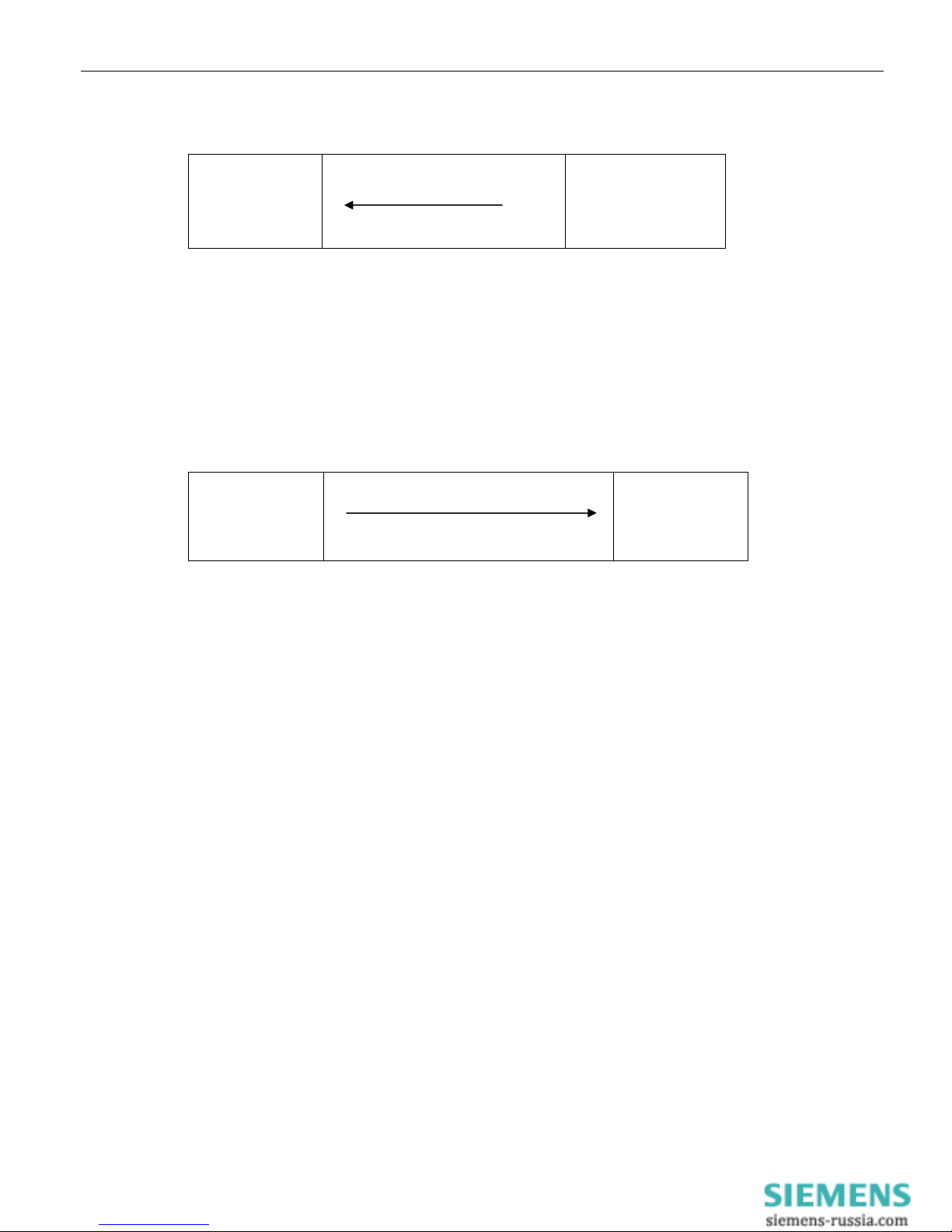
5.2.4 Hardware Data Flow Control with RTS/CTS
Hardware Data Flow Control with the Modem (CTS).
Modem
RS232 Cable
CTS Line
PC or control
When the input buffer of the modem exceeds a certain fill state,
the modem will set the CTS line to OFF. This will indicate to the
modem not to send any more data.
After the modem has operated the input buffer so far that the
XON buffer falls below a certain fill state, it switches the CTS line
on and reports to the PC that it is ready to receive data again.
AT\N1
AT&K3 AT&R1
Pocket Modem 56k Function
Dezember 05 9
5.2.5 Hardware Data Flow Control with the PC (RTS)
Modem
RS232 Cable
RTS Line
PC or control
The PC sets the RTS line to OFF to request the modem to interrupt
the data transmission.
It will depend on the according PC software, if the RTS/CTS lines are
operated from the PC.
The PC sets the RTS line to ON to request data from the modem.
5.2.6 Software Data Flow Control XON and XOFF
Modem
Send data
XON or XOFF character
PC or control
When the input buffer of the modem exceeds a certain fill state, the
modem will insert an XOFF character into the data stream to the PC.
This character will cause the PC to send no more data.
If the PC supports XON/XOFF data flow control will depend on the
according PC software.
After the modem has processed the input buffer so far, it will insert
a XON character into the data stream. This character will cause the
PC to send data again. Analogously, the PC can control the data
stream from the modem to the PC.
The XON/XOFF method is only available when the transmitted data
do not contain the characters XON or XOFF, which usually means
only in actual ASCII texts (7 bit). When binary data (programs, etc.)
are transmitted, also for BTX operation or in the XMODEM
transmission protocol, for example, occasionally appearing XON or
XOFF characters would disturb the operation.
AT&K AT&R
AT&K4

Function Pocket Modem 56K
10 Dezember 05
5.2.7 Reset
There are two reset options:
¾ A reset is performed after the power supply has been interrupted for a
short time.
¾ With the help of the terminal program
After the software reset, load the user profile 0
After the software reset, load the user profile 1
5.2.8 Dial-up Delay
According to the TBR 21 regulations, after 12 futile dial-up
attempts each further dial-up is locked within 2 hours. In this case,
the modem must be temporarily switched off.
The counter is automatically reset after each successfully
established connection.
After the connection has been established, a dial delay of 5
seconds is observed.
5.3 Error Correction
The modem masters the V.42 error correction protocol including
the Microcom Networking Protocol Levels 2/3/4 (MNP2, MNP3,
MNP4) and the data throughput optimization MNP10.
5.3.1 V42 Error Correction
The V.42 error correction includes the protocols LAPM (Link Access
Procedure for Modem) and MNP 4. LAPM is the preferred error
correction.
MNP 4 is supported for compatibility reasons with other MNP
modems. Both methods determine frames to transfer net data
and use CRC (Cyclic Redundancy Check) check sums for error tests.
In V.42, the possibility exists to have the modem identify if the
partner is a V.42 modem, a MNP modem, or a modem without
error correction. The modem can then autonomously adjust to the
partner.
ATZ0 ATZ
ATZ1

Pocket Modem 56k Function
Dezember 05 11
5.3.2 MNP 2/3/4 Error Correction
The MNP error correction can be operated either in block or in
stream mode. The maximum block size can be set to either
64 byte
128 byte
192 byte
and 256 byte.
The MNP error correction can either be set automatically or
activated via AT commands.
5.4 Data Compression
The modem will identify the type of data compression used by
the other modem, or it is fixed on a certain type or no data
compression.
Data compression is only available for error corrected
connections.
To be able to use data compression, both sides (sender and
recipient) must be able to recognize the same data compression
mode.
5.4.1 V.42bis Data Compression
Switch on V.42bis data compression
Switch off V.42bis data compression
V.42bis data compression may only be performed for a V.42
connection (LAP-M or MNP 4). First of all, V.42bis generates a socalled dictionary for the data compression, which contains
frequently used character sequences. After that, only short
references to these character sequences and not the complete
character sequences are transmitted to the other modem.
V.42bis cannot re-pack packed data.
AT%C2
AT%C3
AT%C3
AT%C0
AT\A0
AT\A1
AT\A2
AT\A3
AT\Nn
AT%Cn

Function Pocket Modem 56K
12 Dezember 05
5.4.2 MNP 5 Data Compression
The modem masters the Microcom Networking Protocol Level 5.
MNP 5 data compression can only be performed for an error
corrected MNP 4 connection. MNP 5 replaces frequently used
characters by shorter characters, so-called tokens.
MNP 5 cannot re-pack packed data.
5.4.3 V.44 Data Compression
The V44 data compression offers better compression of typical
Internet content than V.42bis. V.44 also requires an error
corrected connected, just as V.42bis, and cannot re-compress
already compressed data.
Switch off V.44 data compression
Switch on V.44 data compression
AT+DS44=0
AT+DS44=1
AT%C1
AT%C3

Pocket Modem 56k Function
Dezember 05 13
5.5 Selective Call Answer
If the selective call acceptance is activated, the modem will only
accept calls from certain callers. The identification of permitted
callers takes places via the caller ID transmission (CLIP). This
must, however, be supported by the phone system or the
exchange connection, where the modem is connected to.
Activate the selective call acceptance
Deactivate the selective call acceptance
Display a complete list of saved phone numbers for the selective
call answer
Delete the complete phone list for the selective call acceptance
The list of phone numbers has 8 storage locations altogether (N0
to N7). Only if the transmitted phone number matches a phone
number that was entered in the list will the modem accept the
call according to the settings.
e.g.: Store phone number 1234 at storage location 6
The memory N<n> accepts all phone numbers ending
in <nl>.
Our first example activates all phone numbers ending
in 941586920.
The following phone numbers are activated:
0941586920, 0049586920 and +49941586920
Our second example activates all phone numbers
ending in 0941586920.
Only the phone number 0941586920 is activated.
AT&A1
AT&A0
AT*N?
AT*N99=
AT*N<n>=<nr>
AT*N6=123
AT*N7=941586920
AT*N<n>=<nl>
AT*N7=0941586920

Function Pocket Modem 56K
14 Dezember 05
The list of phone numbers may also contain wildcards “'*”. This
allows the activation of entire blocks of phone numbers. The
wild card character (“*”) replaces exactly 1 character of the
phone number
Our example will activate all phone numbers that start
with 94158692** and have 2 more digits (e.g.: an
extension).
The phone number may not contain separators
such as brackets or space characters.
The phone numbers can be deleted individually in two different
ways.
¾ Delete the entered phone number e.g.: Delete the
number stored at the storage location 5
¾ Overwrite the storage location with a new phone
number. e.g.: Storage location 5 with phone
number 456
Display the last phone number whose call was rejected. This
phone number is not saved in the power fail-safe memory of
the modem, i.e. after a restart of the modem the display will be
empty.
AT*Nn=
AT*N5=
AT*Nn=094158692**
AT*N6=094158692**
AT*Nn=456
AT*N5=456
AT%N

Pocket Modem 56k Function
Dezember 05 15
5.6 Send Messages
Note: The sending time of an SMS from the sender to a recipient
depends on the pertinent provider of the service number.
Depending on the degree of utilization and the time of day, an
SMS may be on the way for an extended period.
5.6.1 Transmission Configuration
The modem cannot only send the alarm message to another
analogue modem, but also to a mobile phone as an SMS. Currently
GSM900 and GSM1800, and SMS to fixed networks, fax and e-mail
are available.
The maximum text length is 160 characters.
Protocol settings – see table -
Transmission Protocol Data format Example
Data Connection AT*M0
SMS to Mobile PET 8N1
D1 or
E Network
AT*M1
SMS to Mobile UCP 7E1 AT*M2
SMS to Mobile PET 7E1 AT*M3
SMS to Mobile UCP 8N1 D2 Network AT*M4
Fax AT*M5
SMS to Mobile
or Fixed Network
AT*M6
Enter the service number of the network provider to send
SMS, or the phone number for fax and data connections
Definition of the collective message
Definition of the variable alarm texts and phone numbers to
send SMS (alarm text 1 or 2). After this command is activated,
the modem will query the alarm text.
AT*M<n>
AT&Z0=<Phonenumber>
AT*V
AT*V1
AT*V2

Function Pocket Modem 56K
16 Dezember 05
The modem will reply with
and expects the input of the phone number and the alarm
text in the form
For the transmission, the variable part (maximum of 80
characters) will be attached to the common part (maximum of
160 characters) of the collective message. Of the maximum of
240 characters, the first 160 characters are sent as SMS.
Some network providers support SMS forwarding to a fax
machine or an e-mail address.
All necessary information is available from the customer
service of the provider.
Please find an overview of all required settings for network
providers in German-speaking countries in the attachment.
5.6.2 Triggering
Manual triggering of the alarm message 1 or 2 via the AT
command or by connecting the inputs (PIN18, 20) with
ground.
For the transmission, all in all, 3 attempts (factory default) are
made. These values (1...12) can be changed with the S registry
S13.
When the alarm is triggered via SMS, the modem will return a
status
¾ Message was successfully sent
¾ Error during the message transmission
After the message was sent, the connection is terminated.
5.6.3 Fax Logging
All alarm messages can also be sent to a fax number for
logging reasons.
AT%A<n>
new text:
<Phonenumber,Text>
ATS13=n
OK
ERROR
AT&Z3=<Phonenumber>
Pocket Modem 56k Function
Dezember 05 17
5.7 Remote Configuration (Remote Control)
5.7.1 Mode of Operation
Modem 1
(local modem)
Phone line
Modem 2
(remote modem)
To switch into the remote configuration mode, a data connection must
be established between the modems. A certain connection type is not
mandatory, we recommend, however, to use only error corrected
connections for remote configuration, to avoid transfer errors for the
commands.
The local modem is not required to master any remote configuration
type.
5.7.2 Remote Modem Preparation
Auto answer
Deactivate security callback
Release modem for remote configuration
Save entry
5.7.3 Change Default Password at Remote Modem
Change password
Enter old password
Enter new password
Re-enter new password
AT*C
OLD PASSWORD
QWERTY
ATS0=2
AT&Z1=
AT*R1
AT&W0 AT&W1
NEW PASSWORD
Confirm

Function Pocket Modem 56K
18 Dezember 05
5.7.4 Local Modem Operation
Dial the modem
The modem will establish a successful connection
Switch to the mode “Remote Configuration”
Prompt for entering the password
Enter password (default)
If the entry was successful, the remote modem will send the input
prompt
5.7.5 Reduced Command Set
Some commands may not be executed during remote
configuration and will lead to the following response
5.7.6 Terminate the Remote Configuration Process
Before you complete the remote configuration, save all settings
in profile 0 or 1.
Several commands may be used for termination.
Return to online mode without software reset
Software reset with interruption of all connections
The modem loads the user configuration 0 or 1
****
Remote Access
Remote Passwort:
AT*E AT*X
ATZ0 ATZ1
ATD
<Phonenumber>
Connect
…
QWERTY
>
ATA ATD
ATO AT/B
AT*C AT&F
AT&W0 AT&W1

Pocket Modem 56k Function
Dezember 05 19
5.8 Access Control
5.8.1 Password
To protect yourself from unauthorized access via the phone line,
the modem may be protected by a password. This password is
used to establish a data connection, as well as for security
callback and remote configuration
The default setting is QWERTY
5.8.2 Data Connection
An incoming connection is only released after the caller has
entered the password.
Activate password protection
Deactivate password protection
5.8.3 Security Callback
The feature Security Callback will cause the remote modem to
hang up and call back a preset number.
This function will only be performed after a password has been
entered and is therefore a safe protection against unauthorized
access.
5.8.3.1 Preparation
The activation takes place by saving the call back number in the
phone number registry of the modem that is calling back.
The deactivation takes place by deleting the call back phone
number.
AT*P1
AT*P0
AT*C
AT&Z1=<Phonenumber>
AT&Z1=

Function Pocket Modem 56K
20 Dezember 05
5.8.3.2 Operation
Establishing a connection to the modem.
The connection to the modem is established. The modem
responds to an incoming call, so after 2 seconds the message
“REMOTE PASSWORD” is displayed.
You must now enter the “Remote Password”, which is identical
with the password for the remote configuration.
After the password has been entered correctly, the modem
hangs up and after about 10 seconds dials the stored phone
number. Altogether, 3 dialing attempts with a pause of 10
seconds between each attempt are performed.
If the entered password was incorrect, the connection is
terminated and thus prevents unauthorized access to the
connected device.
After that, a normal data connection is established.
QWERTY
OK
No Carrier
Callback in
Progres
s
ATD <Phonenumber>
Connect
SECURITY CALLBACK
REMOTE PASSWORD:
No Carrie
r
 Loading...