

Siemens Instabus/DALI Gateway N 141 Technical Product Information
GAMMA instabus
Technical product information
January 2006
Instabus / DALI Gateway N 141 5WG1 141-1AB01
Product and functional description
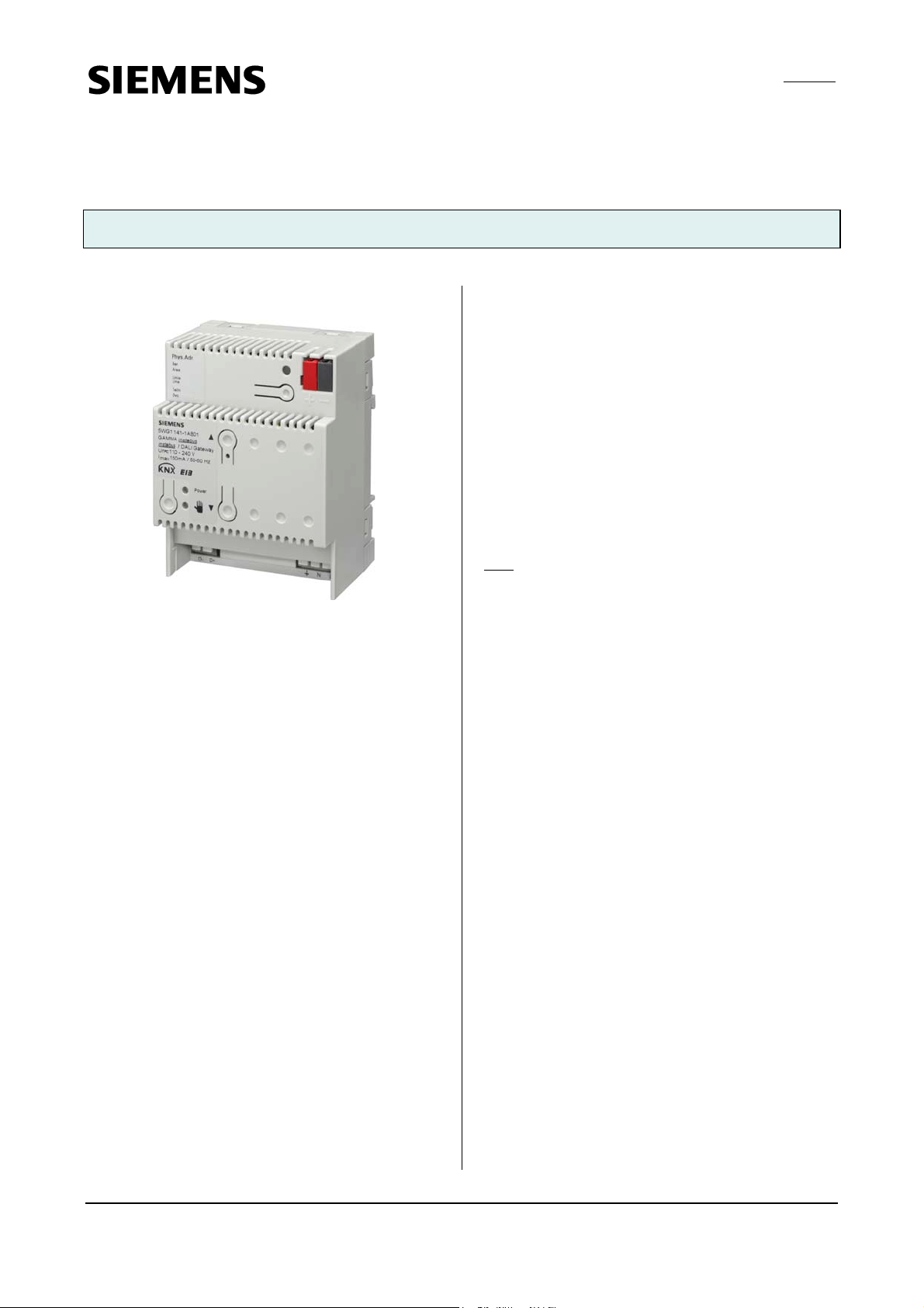
The instabus / DALI gateway N 141 is a KNX EIB device
with one DALI output to which up to 64 DALI actuators
(e.g. DALI ballasts) can be connected to. It is not allowed
to connect DALI sensors to the output of the N 141.
DALI (Digital Addressable Lighting Interface) is a
bidirectional communications interface in accordance
with IEC 60929, whose specification has been defined by
manufacturers of electronic ballasts. It not only enables
the receipt of e.g. switching and dimming commands but
also the sending of status information such as the failure
of a lamp or the report of a detected error in the
electronic ballast. According to IEC 60929 up to 64 DALI
devices can be connected to a DALI bus line and can each
be assigned an individual device address.
The instabus / DALI-Gateway N 141 can be used to
control up to 64 DALI devices over the EIB. They can be
switched and dimmed either individually or in groups.
The N 141 also enables the detection and transmission of
DALI status and failure information. An individual name,
a group, scenes and parameters (refer to the application
program description) are allocated to the individual DALI
electronic ballasts during commissioning with the ETS
(Engineering Tool Software).
The power supply unit integrated in the N 141 supplies
the gateway electronics and generates the DALI bus
voltage. Additionally it enables the operation of the
gateway and a direct switching of all lamps controlled
over its DALI output even if the N 141 has not yet been
commissioned with the ETS or if the communication via
the EIB has been interrupted. For this purpose, the N 141
has a pushbutton located bottom left on its front plate
for switching On the “Direct mode” as well as for
switching back to the “Bus mode”. When this pushbutton
has been pressed for the first time the yellow LED lights
up permanently to indicate direct mode. Then all lamps
controlled over the DALI bus can be together switched
On or Off via the relevant two pushbuttons on the front
plate of the gateway such as via a bus pushbutton:
pressing the upper pushbutton briefly switches the
channel On while pressing the lower push button briefly
switches the channel. A red LED integrated in the upper
push button is used to indicate the state of the lamps by
a continuous light and to indicate an error (e.g. a DALI
bus, ballast or lamp failure) by flashing.
If the direct mode button is pressed for a second time,
the yellow LED to indicate direct mode is extinguished
and the N 141 is switched to “Bus mode”.
Note
: If individual communication with each individual
DALI device is not required and you wish for example to
simply connect a group of dimmable fluorescent lamps in
parallel and control them in the same way as you would
previously have connected and controlled dimmable
electronic control gear (ECG) with a 1...10 V interface,
this is also possible with the switch/dimming actuator N
525E. Status and error signals are also detected by the N
525E and transmitted, whereby these signals are
assigned to the respective group and not to an individual
DALI device.
Application program
25 CO instabus / DALI Gateway 802701
Siemens AG N 141, 5 pages Technical manual
Automation and Drives Group
Electrical Installation Technology © Siemens AG 2006 Update: http://www.siemens.de/gamma
P.O. Box 10 09 53, D-93009 Regensburg Subject to change without further notice
2.5.3.1/1

GAMMA instabus
Technical product information
January 2006
Instabus / DALI Gateway N 141 5WG1 141-1AB01
Connection example
B
I
E
s
u
b
a
t
s
n
i
instabus / DALI Gateway
N 141
t
i
n
u
r
e
g
l
n
p
i
l
p
p
o
u
k
o
n
c
a
s
s
u
u
b
B
I
L
A
D
PE
+
-
N
L
AC 230V
PE
L
N
DALI EVG
DALI ECG 1
+
+
+
+
DALI
-
-
-
-
g
n
N
u
g
r
y
l
PE
PE
PE
PE
o
p
s
r
p
e
u
L
L
L
V
s
Leuchtstofflampe
fluorescent lamp
DALI EVG
DALI ECG 64
+
+
+
+
DALI
-
-
-
-
g
n
N
u
g
r
y
PE
PE
PE
PE
l
o
p
s
r
p
e
u
L
L
L
s
V
Leuchtstofflampe
fluorescent lamp
V
0
3
2
C
A
V
0
3
2
C
A
Installation notes
• The device can be used for permanent installation in
dry, interior rooms and for insertion in distribution
boards or miniature housings.
V
WARNING
• The device must be mounted and commissioned by an
authorised electrician.
• Unoccupied sections of DIN rail with data rail inserted
must be protected with the cover 5WG1 192-8AA01.
• When connecting the device, it should be ensured that
the device can be isolated.
• The device may not be opened.
• When planning and installing electrical installations,
the relevant guidelines, regulations and specifications
of the respective country must be observed.
Technical data
Power supply
• EIB Bus voltage: carried out via the bus line
• EIB bus current: 5 mA (only half a standard bus load ! )
• Electronics and DALI output:
• - integrated power supply for AC/DC 110-240 V, 50-
400 Hz
• - power consumption: max. 7 W
Inputs/outputs
• Mains connection: 3-pole (PE, N, L)
• DALI output (according to IEC 60929):
- max. 64 DALI devices with > 8 kOhm input
impedance
- DALI bus voltage: approx. DC 19 V, floating,
short-circuit-proof
Operating elements
• 1 learning push button:
for toggling between normal mode / addressing mode
• 1 push button:
for toggling between bus mode / direct mode
• 2 push buttons:
for switching all electronic ballasts ON / OFF
Display elements
• 1 red LED:
for checking the bus voltage and for displaying normal
mode / addressing mode
• 1 green LED:
for displaying the 230 V operating voltage
• 1 yellow LED:
for displaying direct mode / bus mode
• 1 red LED per push button:
for ON / OFF status indication (only in direct mode) and
failure indication by blinking with 1 Hz
(communication or illuminant fairlure)
Connections
• Plug-in terminals for mains voltage and DALI output,
insulation strip length 10 ... 11 mm
• The following conductor cross-sections are permitted:
2
- 0.5 ... 3.3 mm
(AWG 12) single-core
- 0.5 ... 3.3 mm2 (AWG 12) stranded multi-core
- 0.5 ... 3.3 mm² (AWG 12) finely stranded, untreated
- 0.5 ... 1.5 mm2 finely stranded, with connector
sleeve
• The supply cable to the N 141 must be fused with a
circuit-breaker of characteristic B or C for a max.
nominal current of 6 A!
• EIB Bus line: Pressure contacts on data rail and bus
terminal
Mechanical data
• Housing: plastic
• Dimensions: DIN rail mounted device in N-system
dimensions, width: 4 module units (1 module unit = 18
mm)
Technical manual N 141, 5 pages Siemens AG
Automation and Drives Group
Update: http://www.siemens.de/gamma © Siemens AG 2006 Electrical Installation Technology
Subject to change without further notice P.O. Box 10 09 53, D-93009 Regensburg
2.5.3.1/2
 Loading...