

Siemens INFINITY Explorer Service manual
s
INFINITY Explorer
Service Manual
ASK-T962-04-7600
EM Guidelines, 1997-04-02

ADVISORY
This document corresponds to the version/revision level effective at the time of system delivery. Revisions to
hardcopy documentation are not automatically distributed.
The installation and service of equipment described herein is to be performed by qualified personnel who are
employed by Siemens or one of its affiliates or who are otherwise authorized by Siemens or one of its affiliates
to provide such services.
Assemblers and other persons who are not employed by or otherwise directly affiliated with or authorized by
Siemens or one of its affiliates are directed to contact one of the local offices of Siemens or one of its affiliates
before attempting installation or service procedures.

INFINITY EXPLORER Field Service Manual
Table of Contents
1 Introduction . . . . . . . . . . . . . . . . . . . . . . . . . . . . . . . . . . . . . . . . . . . . . . . . . . . . . . . . . . . 1
2 MDS Required Hardware . . . . . . . . . . . . . . . . . . . . . . . . . . . . . . . . . . . . . . . . . . . . . . . . 1
3 Infinity Network Interface Requirements . . . . . . . . . . . . . . . . . . . . . . . . . . . . . . . . . . . . 1
4 Hospital Network Interface Requirements . . . . . . . . . . . . . . . . . . . . . . . . . . . . . . . . . . . 1
5 Network Planning . . . . . . . . . . . . . . . . . . . . . . . . . . . . . . . . . . . . . . . . . . . . . . . . . . . . . . 2
5.1 Infinity Network Administrator . . . . . . . . . . . . . . . . . . . . . . . . . . . . . . . . . . . . . . . . . 3
5.2 Hospital Network Administrator . . . . . . . . . . . . . . . . . . . . . . . . . . . . . . . . . . . . . . . . 3
5.3 OEM product Administrator . . . . . . . . . . . . . . . . . . . . . . . . . . . . . . . . . . . . . . . . . . . 3
6 Configuration Worksheets . . . . . . . . . . . . . . . . . . . . . . . . . . . . . . . . . . . . . . . . . . . . . . . 3
6.1 Administrator Contact Information . . . . . . . . . . . . . . . . . . . . . . . . . . . . . . . . . . . . . . 4
6.2 General Configuration Information . . . . . . . . . . . . . . . . . . . . . . . . . . . . . . . . . . . . . . 5
6.3 Infinity Explorer Network Configuration Information . . . . . . . . . . . . . . . . . . . . . . . . . 6
6.4 Infinity Explorer Local DICOM Configuration . . . . . . . . . . . . . . . . . . . . . . . . . . . . . 10
6.5 DICOM Acquisition System . . . . . . . . . . . . . . . . . . . . . . . . . . . . . . . . . . . . . . . . . . 11
7 Network Validation . . . . . . . . . . . . . . . . . . . . . . . . . . . . . . . . . . . . . . . . . . . . . . . . . . . . 12
7.1 Horizontal Wiring . . . . . . . . . . . . . . . . . . . . . . . . . . . . . . . . . . . . . . . . . . . . . . . . . . 12
7.2 LAN Functionality . . . . . . . . . . . . . . . . . . . . . . . . . . . . . . . . . . . . . . . . . . . . . . . . . . 13
8 MDS Installation Overview . . . . . . . . . . . . . . . . . . . . . . . . . . . . . . . . . . . . . . . . . . . . . . 13
9 MDS Hardware Installation . . . . . . . . . . . . . . . . . . . . . . . . . . . . . . . . . . . . . . . . . . . . . . 14
9.1 MDS Mounting Arm Installation . . . . . . . . . . . . . . . . . . . . . . . . . . . . . . . . . . . . . . . 14
9.2 MDS Table Top Installation . . . . . . . . . . . . . . . . . . . . . . . . . . . . . . . . . . . . . . . . . . . 14
10 Monitor Installation . . . . . . . . . . . . . . . . . . . . . . . . . . . . . . . . . . . . . . . . . . . . . . . . . . . . 15
10.1 Flat Screen Display (Art. No. 59 55 567 E531U) . . . . . . . . . . . . . . . . . . . . . . . . . . . 15
10.2 Locally Supplied Monitor . . . . . . . . . . . . . . . . . . . . . . . . . . . . . . . . . . . . . . . . . . . . 17
11 Keyboard, Mouse . . . . . . . . . . . . . . . . . . . . . . . . . . . . . . . . . . . . . . . . . . . . . . . . . . . . . 17
11.1 Wall Mount . . . . . . . . . . . . . . . . . . . . . . . . . . . . . . . . . . . . . . . . . . . . . . . . . . . . . . . 17
11.2 Table Top . . . . . . . . . . . . . . . . . . . . . . . . . . . . . . . . . . . . . . . . . . . . . . . . . . . . . . . . 17
12 Connecting Devices . . . . . . . . . . . . . . . . . . . . . . . . . . . . . . . . . . . . . . . . . . . . . . . . . . . 17
ASK-T962-04-7600 Siemens Medical Solutions, EM-PCS Danvers i
InfExp_sm.fm/01-02/kaupp

Field Service Manual INFINITY EXPLORER
12.1 Infinity Network Connections . . . . . . . . . . . . . . . . . . . . . . . . . . . . . . . . . . . . . . . . . 18
12.1.1 Single Point Connection . . . . . . . . . . . . . . . . . . . . . . . . . . . . . . . . . . . . . . 19
12.1.2 Dual Point Connection . . . . . . . . . . . . . . . . . . . . . . . . . . . . . . . . . . . . . . . 20
12.2 Hospital Network Connections . . . . . . . . . . . . . . . . . . . . . . . . . . . . . . . . . . . . . . . . 21
12.3 Optional Video Cable . . . . . . . . . . . . . . . . . . . . . . . . . . . . . . . . . . . . . . . . . . . . . . . 21
12.3.1 Connecting to a SC 7000 or SC 9000XL Patient Monitor . . . . . . . . . . . . . 21
12.3.2 Connecting to a SC 8000 Patient Monitor . . . . . . . . . . . . . . . . . . . . . . . . 21
13 Syngo Configuration . . . . . . . . . . . . . . . . . . . . . . . . . . . . . . . . . . . . . . . . . . . . . . . . . . . 21
13.1 Syngo Service Window . . . . . . . . . . . . . . . . . . . . . . . . . . . . . . . . . . . . . . . . . . . . . . 22
13.2 Local Host . . . . . . . . . . . . . . . . . . . . . . . . . . . . . . . . . . . . . . . . . . . . . . . . . . . . . . . . 25
13.2.1 Customer and Site . . . . . . . . . . . . . . . . . . . . . . . . . . . . . . . . . . . . . . . . . . 26
13.2.2 TCP/IP LAN Settings . . . . . . . . . . . . . . . . . . . . . . . . . . . . . . . . . . . . . . . . 28
13.2.3 Internet Settings . . . . . . . . . . . . . . . . . . . . . . . . . . . . . . . . . . . . . . . . . . . . 29
13.2.4 User . . . . . . . . . . . . . . . . . . . . . . . . . . . . . . . . . . . . . . . . . . . . . . . . . . . . . 30
13.2.5 Startup . . . . . . . . . . . . . . . . . . . . . . . . . . . . . . . . . . . . . . . . . . . . . . . . . . . 31
13.3 Task Card Configuration . . . . . . . . . . . . . . . . . . . . . . . . . . . . . . . . . . . . . . . . . . . . . 31
13.3.1 PatientView Task Card . . . . . . . . . . . . . . . . . . . . . . . . . . . . . . . . . . . . . . . 32
13.3.2 RemoteView Task Card . . . . . . . . . . . . . . . . . . . . . . . . . . . . . . . . . . . . . . 33
13.3.3 Viewing Task Card . . . . . . . . . . . . . . . . . . . . . . . . . . . . . . . . . . . . . . . . . . 34
13.3.4 Chart Task Card . . . . . . . . . . . . . . . . . . . . . . . . . . . . . . . . . . . . . . . . . . . . 35
13.3.5 WinApplic Task Cards . . . . . . . . . . . . . . . . . . . . . . . . . . . . . . . . . . . . . . . 35
13.4 Service . . . . . . . . . . . . . . . . . . . . . . . . . . . . . . . . . . . . . . . . . . . . . . . . . . . . . . . . . . 36
13.4.1 File & Image Settings . . . . . . . . . . . . . . . . . . . . . . . . . . . . . . . . . . . . . . . . 36
13.4.2 Eventlog . . . . . . . . . . . . . . . . . . . . . . . . . . . . . . . . . . . . . . . . . . . . . . . . . . 37
13.4.3 Backup & Restore Settings . . . . . . . . . . . . . . . . . . . . . . . . . . . . . . . . . . . 38
13.4.4 Licensing . . . . . . . . . . . . . . . . . . . . . . . . . . . . . . . . . . . . . . . . . . . . . . . . . 39
13.5 DICOM Settings . . . . . . . . . . . . . . . . . . . . . . . . . . . . . . . . . . . . . . . . . . . . . . . . . . . 39
13.5.1 Local AEs . . . . . . . . . . . . . . . . . . . . . . . . . . . . . . . . . . . . . . . . . . . . . . . . . 39
13.5.2 Character Settings . . . . . . . . . . . . . . . . . . . . . . . . . . . . . . . . . . . . . . . . . . 40
13.5.3 Network Node Settings . . . . . . . . . . . . . . . . . . . . . . . . . . . . . . . . . . . . . . 41
13.6 Install and Configure a Printer . . . . . . . . . . . . . . . . . . . . . . . . . . . . . . . . . . . . . . . . . 44
13.6.1 Printer Installation . . . . . . . . . . . . . . . . . . . . . . . . . . . . . . . . . . . . . . . . . . . 44
13.6.2 Printer Configuration . . . . . . . . . . . . . . . . . . . . . . . . . . . . . . . . . . . . . . . . 50
13.7 WebView Setup . . . . . . . . . . . . . . . . . . . . . . . . . . . . . . . . . . . . . . . . . . . . . . . . . . . 52
ii Siemens Medical Solutions, EM-PCS, Danvers ASK-T962-04-7600
InfExp_sm.fm/01-02/kaupp

INFINITY EXPLORER Field Service Manual
13.8 Customize IE WinApplic Task Card . . . . . . . . . . . . . . . . . . . . . . . . . . . . . . . . . . . . . 53
13.9 Language Setup . . . . . . . . . . . . . . . . . . . . . . . . . . . . . . . . . . . . . . . . . . . . . . . . . . . 54
13.10Loading Windows Application Programs . . . . . . . . . . . . . . . . . . . . . . . . . . . . . . . . 55
13.10.1 CDROM Share Configuration . . . . . . . . . . . . . . . . . . . . . . . . . . . . . . . . . . 56
13.10.2 Laptop TCP/IP Setup . . . . . . . . . . . . . . . . . . . . . . . . . . . . . . . . . . . . . . . . 57
13.10.3 Load Application Software . . . . . . . . . . . . . . . . . . . . . . . . . . . . . . . . . . . . 59
13.10.4 Access Syngo Service . . . . . . . . . . . . . . . . . . . . . . . . . . . . . . . . . . . . . . . 60
13.10.5 Configure WinApplic Task Card . . . . . . . . . . . . . . . . . . . . . . . . . . . . . . . . 63
14 Removing Application Programs . . . . . . . . . . . . . . . . . . . . . . . . . . . . . . . . . . . . . . . . . . 64
15 Backup Syngo Configuration . . . . . . . . . . . . . . . . . . . . . . . . . . . . . . . . . . . . . . . . . . . . . 65
15.1 Save Backup Files to MDS . . . . . . . . . . . . . . . . . . . . . . . . . . . . . . . . . . . . . . . . . . . 65
15.2 Setup Laptop for MDS Network Connection . . . . . . . . . . . . . . . . . . . . . . . . . . . . . 65
15.2.1 TCP/IP Setup . . . . . . . . . . . . . . . . . . . . . . . . . . . . . . . . . . . . . . . . . . . . . . 66
15.2.2 Drive Share Configuration . . . . . . . . . . . . . . . . . . . . . . . . . . . . . . . . . . . . 68
15.3 Transfer Files . . . . . . . . . . . . . . . . . . . . . . . . . . . . . . . . . . . . . . . . . . . . . . . . . . . . . 69
16 Software Reinstallation . . . . . . . . . . . . . . . . . . . . . . . . . . . . . . . . . . . . . . . . . . . . . . . . . 70
16.1 Required Materials . . . . . . . . . . . . . . . . . . . . . . . . . . . . . . . . . . . . . . . . . . . . . . . . . 71
16.2 Infinity Explorer Software Reinstallation . . . . . . . . . . . . . . . . . . . . . . . . . . . . . . . . . 71
16.3 Infinity Explorer Software/NT4 Reinstallation . . . . . . . . . . . . . . . . . . . . . . . . . . . . . 71
16.3.1 TCP/IP Setup . . . . . . . . . . . . . . . . . . . . . . . . . . . . . . . . . . . . . . . . . . . . . . 72
16.3.2 CDROM Share Configuration . . . . . . . . . . . . . . . . . . . . . . . . . . . . . . . . . . 74
16.3.3 Install MDS Utility . . . . . . . . . . . . . . . . . . . . . . . . . . . . . . . . . . . . . . . . . . . 75
16.4 MDS to Service Laptop Interface . . . . . . . . . . . . . . . . . . . . . . . . . . . . . . . . . . . . . . 76
16.5 Launch MDS Utility . . . . . . . . . . . . . . . . . . . . . . . . . . . . . . . . . . . . . . . . . . . . . . . . . 76
16.6 MDS Network Boot . . . . . . . . . . . . . . . . . . . . . . . . . . . . . . . . . . . . . . . . . . . . . . . . 78
16.7 Transfer Infinity Explorer NT4 Image . . . . . . . . . . . . . . . . . . . . . . . . . . . . . . . . . . . 79
16.8 Install Infinity Explorer Software . . . . . . . . . . . . . . . . . . . . . . . . . . . . . . . . . . . . . . . 82
16.9 Restore Configuration . . . . . . . . . . . . . . . . . . . . . . . . . . . . . . . . . . . . . . . . . . . . . . . 83
17 Phoenix BIOS Phlash . . . . . . . . . . . . . . . . . . . . . . . . . . . . . . . . . . . . . . . . . . . . . . . . . . 84
17.1 Hardware Setup . . . . . . . . . . . . . . . . . . . . . . . . . . . . . . . . . . . . . . . . . . . . . . . . . . . 84
17.2 Software Setup . . . . . . . . . . . . . . . . . . . . . . . . . . . . . . . . . . . . . . . . . . . . . . . . . . . . 85
17.2.1 CDROM Setup Procedure . . . . . . . . . . . . . . . . . . . . . . . . . . . . . . . . . . . . 85
17.2.2 Download Setup Procedure . . . . . . . . . . . . . . . . . . . . . . . . . . . . . . . . . . . 86
17.3 MDS Hard Drive Phlash Procedure . . . . . . . . . . . . . . . . . . . . . . . . . . . . . . . . . . . . . 87
ASK-T962-04-7600 Siemens Medical Solutions, EM-PCS Danvers iii
InfExp_sm.fm/01-02/kaupp

Field Service Manual INFINITY EXPLORER
18 Replacement Procedures . . . . . . . . . . . . . . . . . . . . . . . . . . . . . . . . . . . . . . . . . . . . . . . 88
18.1 Opening MDS . . . . . . . . . . . . . . . . . . . . . . . . . . . . . . . . . . . . . . . . . . . . . . . . . . . . . 89
18.2 Replacing Battery . . . . . . . . . . . . . . . . . . . . . . . . . . . . . . . . . . . . . . . . . . . . . . . . . . 91
18.3 Replacing Hard Drive . . . . . . . . . . . . . . . . . . . . . . . . . . . . . . . . . . . . . . . . . . . . . . . 92
18.4 Replacing Memory / Daughterboard . . . . . . . . . . . . . . . . . . . . . . . . . . . . . . . . . . . . 93
18.5 Closing MDS . . . . . . . . . . . . . . . . . . . . . . . . . . . . . . . . . . . . . . . . . . . . . . . . . . . . . . 94
19 Troubleshooting . . . . . . . . . . . . . . . . . . . . . . . . . . . . . . . . . . . . . . . . . . . . . . . . . . . . . . 95
19.1 Power Problem . . . . . . . . . . . . . . . . . . . . . . . . . . . . . . . . . . . . . . . . . . . . . . . . . . . . 95
19.1.1 No Response when power On/Off switch toggled ON . . . . . . . . . . . . . . 95
19.1.2 Power On/Off Piezo Tone Fails to Sound. . . . . . . . . . . . . . . . . . . . . . . . . 96
19.1.3 Power-Up Sequence Fails to Complete Properly . . . . . . . . . . . . . . . . . . . 96
19.1.4 No Video display . . . . . . . . . . . . . . . . . . . . . . . . . . . . . . . . . . . . . . . . . . . . 97
19.1.5 MDS Fails to boot properly . . . . . . . . . . . . . . . . . . . . . . . . . . . . . . . . . . . 97
19.2 BIOS Setup . . . . . . . . . . . . . . . . . . . . . . . . . . . . . . . . . . . . . . . . . . . . . . . . . . . . . . . 98
20 Functional Verification . . . . . . . . . . . . . . . . . . . . . . . . . . . . . . . . . . . . . . . . . . . . . . . . . 101
20.1 Power Circuits and Startup . . . . . . . . . . . . . . . . . . . . . . . . . . . . . . . . . . . . . . . . . . 101
20.2 Task Card Functionality . . . . . . . . . . . . . . . . . . . . . . . . . . . . . . . . . . . . . . . . . . . . . 101
20.3 Windows Application Programs . . . . . . . . . . . . . . . . . . . . . . . . . . . . . . . . . . . . . . 101
21 Leakage Current Test . . . . . . . . . . . . . . . . . . . . . . . . . . . . . . . . . . . . . . . . . . . . . . . . . 102
Functional Verification Checklist . . . . . . . . . . . . . . . . . . . . . . . . . . . . . . . . . .104
Appendix A: Spare Parts . . . . . . . . . . . . . . . . . . . . . . . . . . . . . . . . . . . . . . . .105
Appendix B: Bios Messages . . . . . . . . . . . . . . . . . . . . . . . . . . . . . . . . . . . . .109
Appendix C: POST Error Codes . . . . . . . . . . . . . . . . . . . . . . . . . . . . . . . . . . .113
Appendix D: Infini t y Exp lo rer Net w o r k Re qu i r ements Check List . . . . . . . . .1 1 9
Appendix E: SC7/8/9kXL VE2.0-W SWI . . . . . . . . . . . . . . . . . . . . . . . . . . . . .121
iv Siemens Medical Solutions, EM-PCS, Danvers ASK-T962-04-7600
InfExp_sm.fm/01-02/kaupp

INFINITY EXPLORER Field Service Manual
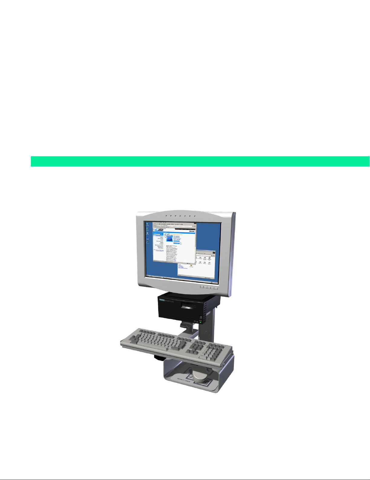
1Introduction INFINITY
user to extend the viewing capability of Siemens SC 7000, SC 8000 and
SC 9000XL monitors. I
a dedicated MDS workstation. The graphical user interface is a task card
resembling folder tabs. Through these tabs (Task Cards), the user can
select information from departments such as CIS, HIS, Web, Imaging
Department, etc., and view images and waveforms on one display.
2MDS Required
Hardware
3INFINITY Network
Interface
Requirements
In addition to these installation instructions, hardware required to install an
MDS is as follows:
• One - Language specific Keyboard
• One - Mouse
• One - Ethernet cable (if connecting to a LAN)
• One - VGA/SVGA monitor as defined in INFINITY EXPLORER User
• DC Power Adapter (refer to original ordering data sheet)
• Keyboard, Mouse, Ethernet cable and Monitor can be either
The INFINITY EXPLORER connects to an SC 7000, SC 8000 or SC 9000XL
Patient Monitor by means of an I
3COM switching Hub. As of the publication date of this Manual, the
following requirements must be met for I
TM
EXPLORER is a Syngo based software program that allows the
NFINITY EXPLORER software is intended to be run on
Guide
ordered from the factory (see optional hardware below) or
purchased separately from a local Siemens Representative.
NFINITY IDS and the INFINITY LAN, via a
NFINITY Network communication.
4 Hospital Network
Interface
Requirements
Note: Refer to the Software Compatibility Chart shipped with every
Siemens software release for any change in software compatibility.
Table 3-1 INFINITY Hardware/Software Requirements
Hardware Software
SC 7000, SC 8000, SC 9000XL VE2.0
I
NFINITY IDS >VF2
NFINITY CPS >VF1.X
I
3COM Switching Hub Version 2.62
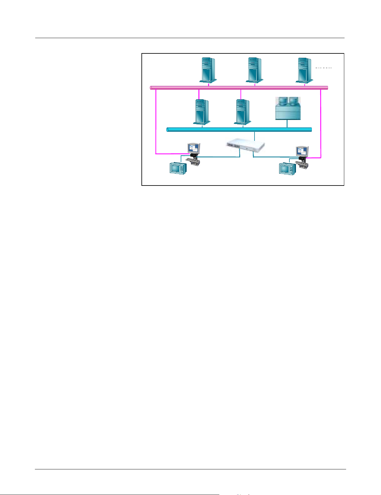
The INFINITY EXPLORER connects to Hospital DICOM Servers, Web-based
servers, and certain NT4 based Application servers, via the Hospital LAN.
See Figure 3-1 on page 2. The following requirements must be met for
Hospital Network communication.
Table 4-1 Hospital LAN Hardware/Software Requirements
Hardware Software
Web-Based Server HTML compliant
DICOM Server W DICOM 3.0 standard
Web Server Compatible with Internet Explorer
5.01 (Service Pack 2)
Application Server Windows NT4 with Service Pack 6
ASK-T962-04-7600 Siemens Medical Solutions, EM-PCS Danvers 1
InfExp_sm.fm/01-02/kaupp
Field Service Manual INFINITY EXPLORER
Proxy
Hospital LAN / WWW
Hospital LAN / WWW
Hospital LAN / WWW
Hospital LAN / WWW
Infinity LAN
Infinity LAN
Infinity LAN
Infinity LAN
Infinity LAN
Infinity LAN
Infinty
Infinty
Exlporer
Exlporer
SC7000 & IDS
SC7000 & IDS
Webview
Webview
Webview
Server
Server
Server
Proxy
Server
Server
Chart Assist
Chart Assist
Chart Assist
Chart Assist
Server
Server
Server
Server
Switching Hub
Switching Hub
HIS
HIS
Server
Server
Central Station
Central StationCentral Station
3COM 3300
3COM 3300
SC7000 & IDS
SC7000 & IDS
Infinty
Infinty
Exlporer
Exlporer
DICOM
DIACOM
DIACOM
DIACOM
Server(s)
Server(s)
Server(s)
Server(s)
Figure 3-1 Hospital, INFINITY Network
5 Network Planning In addition to providing an additional 31 waveforms from a Siemens
SC 7000, SC 8000 or SC 9000XL Patient Monitor, the I
also designed to receive data from multiple hospital servers and to display
data at the patient bedside. Server information that can be displayed by the
I
NFINITY EXPLORER consists of the following examples.
NFINITY EXPLORER is
•INFINITY WinView Gateway data
• HIS data (HTML format)
• CIS data (HTML format)
•DICOM data
• Hospital Intranet data
• Internet data
• Windows NT4 Application Server
The INFINITY EXPLORER receives Network data from a Siemens SC 7000,
SC 8000 or SC 9000XL Patient Monitor via the I
NFINITY Network LAN and
the Hospital LAN, using two separate RJ45 Network Interface Cards (NIC).
The Hospital LAN connects to one NIC through a single RJ45 port at the
rear panel of the Medside Data Station (MDS) while Patient Monitor and
I
NFINITY LAN data connect to the MDS through a built-in repeater hub, also
located at the rear of the MDS. A 3COM Switching hub provides Network
filtering that isolates I
Network. Since Multiple LAN’s are involved in I
most of the I
NFINITY Installation planning must be coordinated prior to the
NFINITY EXPLORER packet data from the INFINITY
NFINITY EXPLORER operation,
actual installation of the MDS, System Administrators for each LAN in
which the I
I
NFINITY EXPLORER installation. This includes the following:
NFINITY EXPLORER is to be connected must be involved with the
•INFINITY Network Administrator
• Hospital Network Administrator
• OEM product Administrator (GE DICOM Server, Picis HIS
Server...etc)
2 Siemens Medical Solutions, EM-PCS, Danvers ASK-T962-04-7600
InfExp_sm.fm/01-02/kaupp

INFINITY EXPLORER Field Service Manual
5.1 INFINITY Network Administrator
5.2 Hospital Network Administrator
The INFINITY Network Administrator provides the MDS computer name and
a unique I
the I
I
NFINITY Network IP address and Subnet Mask schemes. The INFINITY
NFINITY Network IP address for each INFINITY EXPLORER. Refer to
NFINITY Network Planning, Design, and Installation Handbook for
Network Administrator also provides network configuration information for
other I
NFINITY Network Servers with which the INFINITY EXPLORER may
interface.
Note: At time of publication of this document, the INFINITY Network
Planning, Design, and Installation Handbook does not provide a
block of IP addresses for I
using the I
NFINITY Network Planning, Design, and Installation
NFINITY EXPLORER use. Siemens suggests
Handbook scheme as it pertains to IP address allocation. The form
of an IP address is “w.x.y.z”. Siemens has assigned w=191 and
x=1, “y” stands for the Monitor Unit ID, and “z” stands for the
Host (in this case, I
NFINITY EXPLORER) ID. For INFINITY EXPLORER,
Siemens suggests starting with host ID 200, then increment by
one for each additional I
NFINITY EXPLORER.
The Hospital Administrator must provide Hospital LAN configuration
information needed to allow I
LAN. Configuration worksheets with data needed to configure the I
E
XPLORER are included in Section 6 of this document. During the pre-
NFINITY EXPLORER connectivity to the Hospital
NFINITY
installation planning meetings the Hospital Administrator provides
worksheet configuration information. In most cases, the Hospital
Administrator can also provide configuration information for OEM products
that are connected to the Hospital LAN.
5.3 OEM product Administrator
6Configuration
Worksheets
If the Hospital Administrator cannot provide configuration information, the
OEM Administrator must provide OEM LAN configuration information
needed to allow I
Configuration worksheets with data needed to configure the I
E
XPLORER are included in Section 6 of this document. During the pre-
NFINITY EXPLORER connectivity to the OEM Server.
NFINITY
installation planning meetings, the OEM Administrator provides worksheet
configuration information.
The following tables are for reference purposes. A copy of the following
Worksheets are distributed during the pre-Installation meeting with the
Hospital Admin ist rat or , I
Administrator (conducted one month before actual I
NFINITY Network Administrator, and OEM product
NFINITY EXPLORER
installation date).
To assure working effectively during startup, it is necessary to FIRST
summarize the configuration data in the following tables.
Note: In the following tables, bold text indicates Siemens
Customer Service Engineer supplied data, Italic text indicates
Siemens Sales Representative supplied data, and shaded boxes
indicate Hospital IT Administrator supplied data.
ASK-T962-04-7600 Siemens Medical Solutions, EM-PCS Danvers 3
InfExp_sm.fm/01-02/kaupp

Field Service Manual INFINITY EXPLORER
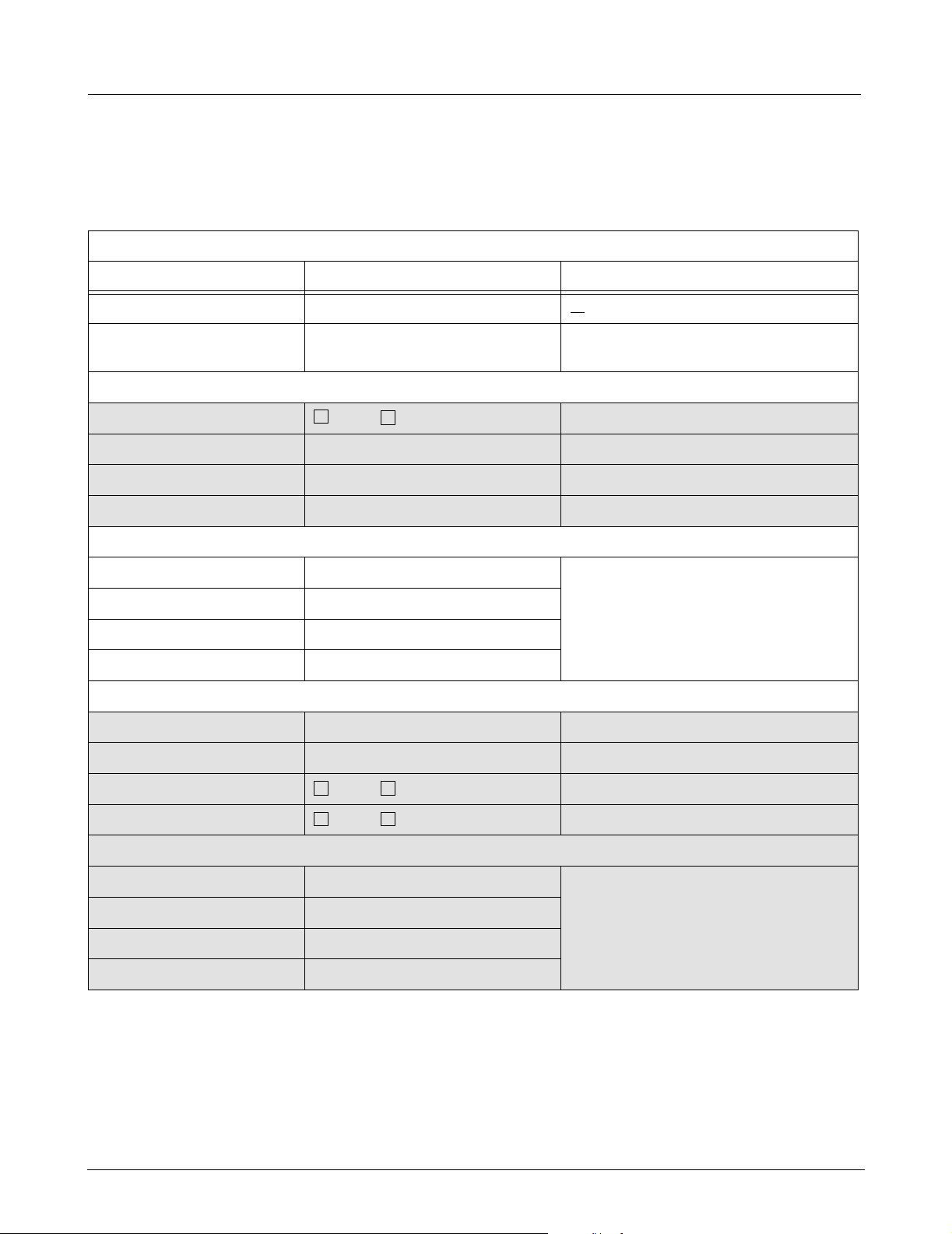
6.1 Administrator Contact Information
Table 6-1 Administrator Contact Information
Administrator Contact Information
Input Field Input Field Data Notes
Siemens Customer Service
Engineer (CSE) name
Siemens Customer Service
Engineer office mail address
Siemens Customer Service
Engineer email address
Siemens Customer Service
Engineer fax number
Siemens Sales Representative
name
Siemens Sales
Representative office mail
address
Siemens Sales
Representative email
address
Siemens Sales
Representative fax number
Hospital IT Administrator
name
Hospital IT Administrator
office mail address
Hospital IT Administrator
email address
Hospital IT Administrator fax
number
OEM Administrator name
OEM Administrator office mail
address
OEM Administrator email
address
OEM Administrator fax
number
4 Siemens Medical Solutions, EM-PCS, Danvers ASK-T962-04-7600
InfExp_sm.fm/01-02/kaupp

INFINITY EXPLORER Field Service Manual
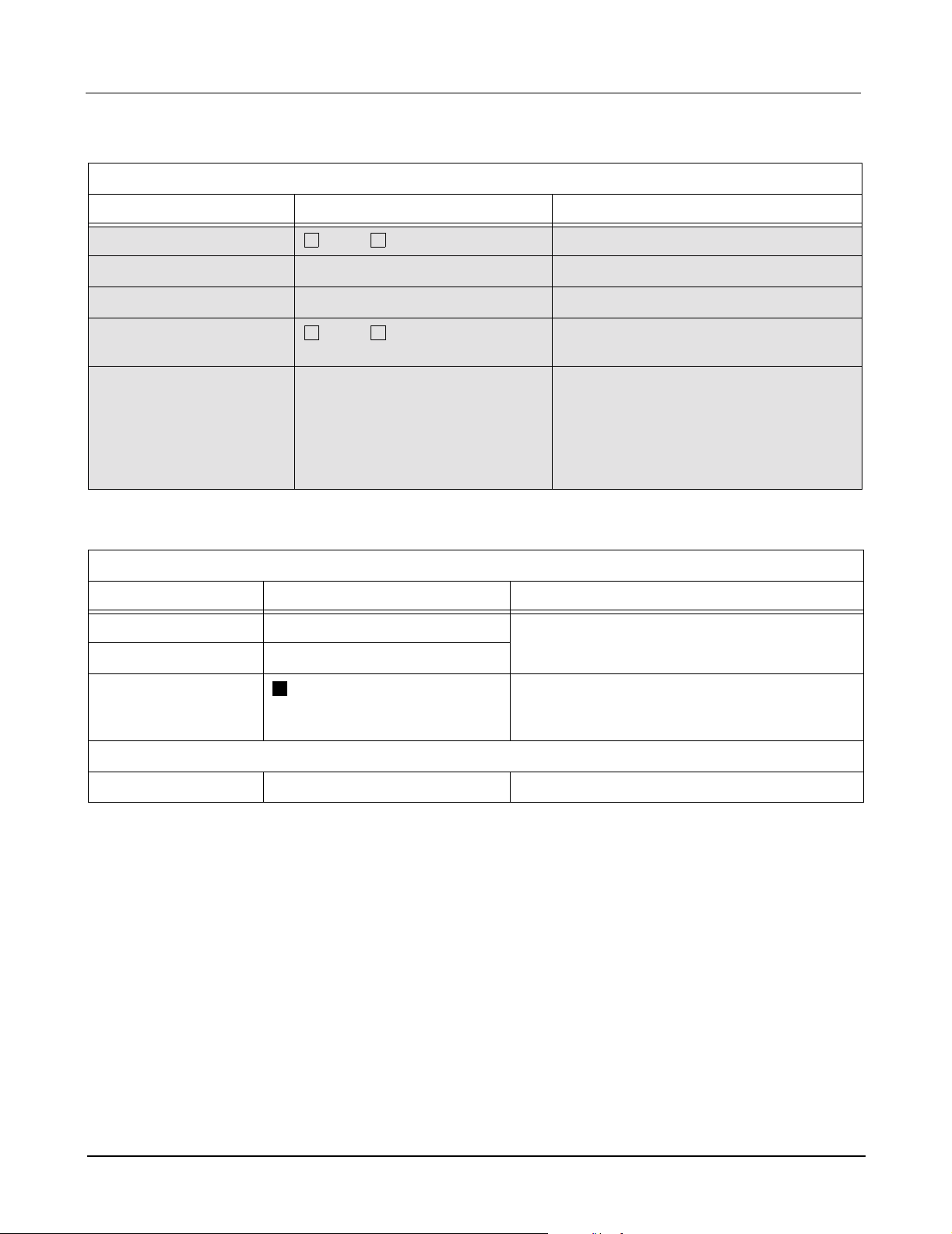
6.2 General Configuration Information
Table 6-2 Service Configuration Information
Service Information
Input Field Input Field Data Notes
Service Key The service key is shipped with each
I
NFINITY EXPLORER MDS. The Service key is
I
NFINITY EXPLORER Serial
Number
I
NFINITY EXPLORER
Hardware (MAC) address
USC telephone number
Table 6-3 Customer Demographic Information
derived from the I
(MAC) hardware address.
NFINITY EXPLORER NIC
Customer Information
Input Field Input Field Data Notes
Product Art. No.
Order Number (BZ No.)
Hospital Name
Hospital ID
Product Name Infinity Explorer
Hospital Street
Hospital Street Number
Hospital Zip Code
Hospital Phone
City
District
Country
Customer Information (At time of Installation
Service Headquarter
Phone No.
ASK-T962-04-7600 Siemens Medical Solutions, EM-PCS Danvers 5
InfExp_sm.fm/01-02/kaupp
Field Service Manual INFINITY EXPLORER
6.3 INFINITY Explorer Network Configuration Information
Table 6-4 INFINITY EXPLORER Network Settings
INFINITY Explorer Network Settings
Input Field Input Field Data Notes
Computer Name <
I
NFINITY EXPLORER Serial
Number
Hospital LAN Adapter (Network Adapter 1)
Use DHCP Server
IP address
Subnet Mask
Gateway
IP address SIEMENS suggests using the INFINITY
Subnet Mask
Gateway
Laser Printer IP
Primary WINS server
Secondary WINS server
Yes No
INFINITY Network LAN Adapter (Network Adapter 2)
WINS
7 Characters
Select NO
Network Planning, Design, and
Installation Handbook scheme as it
pertains the IP address allocation
Enable DNS for Windows
Enable LMHOSTS Lookup
DNS
Domain / Workgroup Several DNS nodes are definable
1 DNS service search order
2 DNS service search order
3 DNS service search order
6 Siemens Medical Solutions, EM-PCS, Danvers ASK-T962-04-7600
Yes No
Yes No
InfExp_sm.fm/01-02/kaupp
INFINITY EXPLORER Field Service Manual
Table 6-5 Internet Proxy Settings
Internet Proxy Settings
Input Field Input Field Data Notes
Use Proxy Server
Yes No
Proxy Server Address
Proxy Server Port
Bypass Proxy Server for
Yes No
Local Address
Exceptions Do NOT use Proxy Server for addresses
beginning with colons (:). Use
semicolons (;) to separate entries.
Note: If connecting to a Siemens Chart
Assist and/or WebView Server, type that
servers URL in Exceptions box.
Table 6-6 User Account Settings
Configure User Account
Input Field Input Field Data Notes
Account for UI Leave Default (default is med user) If
Default Password
Enable Auto login
Yes
password / account is changed, Consult/
Inform Hospital IT Staff
Used to Auto start I
NFINITY EXPLORER
application without Logon and Password
control
Account for PPP (Account name is: PPP)
Default Password Leave Default
ASK-T962-04-7600 Siemens Medical Solutions, EM-PCS Danvers 7
InfExp_sm.fm/01-02/kaupp

Field Service Manual INFINITY EXPLORER
Table 6-7 Task Card Settings
Task Card Settings
Input Field Input Field Data Notes
Patient View
Enable Patient View
Yes No
Name Patient View Type name that will appear on UI Taskcard
Local Bed Device Name INFINITY Bed Name for SC7/8000/900 0XL
Local Bed IP address IP address as it appears
Remote View
Enable Remote View
Yes No
Check “Yes” if I
connecting to an I
NFINITY EXPLORER is
NFINITY Gateway WebView
Server. Check “No” if I
not connecting to an I
NFINITY EXPLORER is
NFINITY Gateway
WebView Server.
Name Remote View Type name that will appear on UI Taskcard
URL 1 x 1 Type URL location of I
NFINITY Gateway
WebView Server (e.g. http:/171.171.1.1/
Zeus4Panel/index.htm) Ensure URL is typed
in Exceptions box in
Alt URL 2 x 2 Type Alternate URL location of I
NFINITY
Gateway WebView Server (e.g. http:/
171.171.1.1/Zeus4Panel/index1.htm) Ensure
URL is typed in Exceptions box in
Viewing
Enable Viewing Taskcard
Yes No
Check “Yes” if I
NFINITY EXPLORER is
connecting to a DICOM Server. Check “No”
if I
NFINITY EXPLORER is not connecting to a
DICOM Server.
ChartAssist
Enable Chart View
Yes No
Check “Yes” if I
connecting to an I
Check “No” if I
NFINITY EXPLORER is not
connecting to an I
NFINITY EXPLORER is
NFINITY ChartAssist Server.
NFINITY ChartAssist Server.
Name Chart View Type name that will appear on UI Taskcard
URL Chart View Type URL location of I
NFINITY ChartAssist
Server (e.g. http:/172.172.1.1/Prometheus/
PatientLogin.asp) Ensure URL is typed in
Exceptions box in
Timer DO NOT CHANGE DO NOT CHANGE
8 Siemens Medical Solutions, EM-PCS, Danvers ASK-T962-04-7600
InfExp_sm.fm/01-02/kaupp

INFINITY EXPLORER Field Service Manual
Table 6-7 Task Card Settings (Continued)
Task Card Settings
Input Field Input Field Data Notes
WinApplic 1 View
Enable WinApplic 1 View
Yes No
Check “Yes” if INFINITY EXPLORER is
connecting to a Hospital / Clinic Custom
Web Browser or Applications Server. Check
“No” if I
NFINITY EXPLORER is not connecting
to a Hospital / Clin ic Custom Web Browser
or Applications Server.
Name WinApplic 1 View Type name that will appear on UI Taskcard
URL WinApplic 1 View If connecting to Web Server, type
D:\Program Files\Internet
Explorer\IEXPLORE.EXE
If connecting to a Program (e.g. Microsoft
Word, type path that corresponds to
Programs executable file (e.g. D:\Program
Files\Microsoft
WinApplic 2 View
Enable WinApplic 2 View
Yes No
Check “Yes” if I
NFINITY EXPLORER is
connecting to a Hospital / Clinic Custom
Web Browser or Applications Server. Check
“No” if I
NFINITY EXPLORER is not connecting
to a Hospital / Clinic custom Web Browser or
Applications Server.
Name WinApplic 2 View Type name that will appear on UI Taskcard
URL WinApplic 2 View If connecting to Web Server, type
D:\Program Files\Internet
Explorer\IEXPLORE.EXE
If connecting to a Program (e.g. Microsoft
Word, type path that corresponds to
Programs executable file (e.g. D:\Program
Files\Microsoft
ASK-T962-04-7600 Siemens Medical Solutions, EM-PCS Danvers 9
InfExp_sm.fm/01-02/kaupp

Field Service Manual INFINITY EXPLORER
Table 6-7 Task Card Settings (Continued)
Task Card Settings
Input Field Input Field Data Notes
WinApplic 3 View
Enable WinApplic 3 View
Yes No
Check “Yes” if I
NFINITY EXPLORER is
connecting to a Hospital / Clinic Custom
Web Browser or Applications Server. Check
“No” if I
NFINITY EXPLORER is not connecting
to a Hospital / Clin ic Custom Web Browser
or Applications Server.
Name WinApplic 3 View Type name that will appear on UI Taskcard
URL WinApplic 3 View If connecting to Web Server, type
D:\Program Files\Internet
Explorer\IEXPLORE.EXE
If connecting to a Program (e.g. Microsoft
Word, type path that corresponds to
Programs executable file (e.g. D:\Program
Files\Microsoft
WinApplic 4 View
Enable WinApplic 4 View
Yes No
Check “Yes” if I
NFINITY EXPLORER is
connecting to a Hospital / Clinic Custom
Web Browser or Applications Server. Check
“No” if I
NFINITY EXPLORER is not connecting
to a Hospital / Clin ic Custom Web Browser
or Applications Server.
Name WinApplic 4 View Type name that will appear on UI Taskcard
URL WinApplic 4 View If connecting to Web Server, type
D:\Program Files\Internet
Explorer\IEXPLORE.EXE
If connecting to a Program (e.g. Microsoft
Word, type path that corresponds to
Programs executable file (e.g. D:\Program
Files\Microsoft
6.4 INFINITY EXPLORER Local DICOM Configuration
Table 6-8 includes required information that is needed during the INFINITY
E
XPLORER installation and configuration phase. The CSE uses this
information to configure the I
NFINITY EXPLORER’s local DICOM information
and the DICOM server Administrator to configure the Server to allow
I
NFINITY EXPLORER access.
Note: Each DICOM Server that INFINITY EXPLORER accesses must
be configured to provide I
NFINITY EXPLORER access rights.
Services supported
Storage SCU Yes
Storage SCP Yes
Query /Retrieve Yes
10 Siemens Medical Solutions, EM-PCS, Danvers ASK-T962-04-7600
InfExp_sm.fm/01-02/kaupp
INFINITY EXPLORER Field Service Manual
Table 6-8 Infinity Explorer DICOM Server Configuration Information
I
NFINITY EXPLORER DICOM information
Input Field Input Field Data Notes
DICOM Server Location Not necessary for the configuration but
useful information for troubleshooting
purposes.
DICOM Server Manufacturer Name Siemens
DICOM Server SW version
DICOM Server Host (Node) Name (See “Computer Name” in Table 6-4)
DICOM Server IP address Not necessary if a DNS or WINS name
solution is possible. (See Hospital LAN
Adapter IP address in Table 6-4).
DICOM Server Logical name (See “Computer Name” in Table 6-4)
DICOM Server Default Node N/A
DICOM Application Entity Title (AET)
and Port number
Storage SCP
AET:
Port:104
Query
Retrieve
Q/R SCP AET:
Port:104
Supported Transfer Syntax:
Implicit little endian
Explicit little endian
Explicit big endian
Supporte d Co m p res si on
JPEG Lossy
JPEG Lossless
6.5 DICOM Acquisition System
Fill in a copy of Table 6-9 for each DICOM server that INFINITY EXPLORER
accesses.
Services supported
Yes No
Yes No
Yes No
Yes No
Yes No
Yes No
Yes No
For AET, see “Computer Name” in
Table 6-4, then add AN_ before Computer
name (e.g. if Computer name is MDS1,
then AET is AN_MDS1)
For Port, always use Port 104
If necessary, check DICOM conformance
statement.
If necessary, check DICOM conformance
statement.
If necessary, check DICOM conformance
statement.
Storage SCU Yes
Storage SCP Yes
Query /Retrieve Yes
ASK-T962-04-7600 Siemens Medical Solutions, EM-PCS Danvers 11
InfExp_sm.fm/01-02/kaupp
Field Service Manual INFINITY EXPLORER
Table 6-9 DICOM Server Configuration Information
DICOM Server Functio nal it y
Input Field Input Field Data Notes
DICOM Server Location Not necessary for the configuration but
useful information for troubleshooting
purposes.
DICOM Server Manufacturer Name
DICOM Server SW version
DICOM Server Host (Node) Name
DICOM Server IP address Not necessary if a DNS or WINS name
solution is possible.
DICOM Server Logical name
DICOM Server Default Node
DICOM AE Title and port number
Storage SCP
AET:
Port:
Query
Retrieve
Yes No
Yes No
If necessary, check DICOM conformance
statement.
Q/R SCP AET:
Port:
Supported Transfer Syntax:
Implicit little endian
Explicit little endian
Explicit big endian
Supported Compression
JPEG Lossy
JPEG Lossless
Yes No
Yes No
Yes No
Yes No
Yes No
If necessary, check DICOM conformance
statement.
If necessary, check DICOM conformance
statement.
7 Network Validation Network Validation includes verifying Horizontal Wiring is complete,
Network Hardware (e.g. switching hubs, routers) has been installed and
Network functionality meets at least minimum requirements for I
E
XPLORER Inst all atio n .
7.1 Horizontal Wiring Installation of an INFINITY EXPLORER has two distinct phases -- (1) installation
of horizontal (premise) and backbone wiring (refer to Chapter 4 of the
I
NFINITY Network Planning, Design, and Installation Handbook, Art No. 59
46 459 E537U), including the 3Com Ethernet Switching Hub, and (2)
installation of I
NFINITY EXPLORER MDSs.
NFINITY
Installation of horizontal wiring includes pulling category 5 cable through
conduits or over ceilings. It also includes terminating cable at both bedside
wall box (end node) and at wiring hub (patch panel), and installing all other
directly related hardware such as wall boxes, patch panels, and Ethernet
repeater hub(s). In addition it includes terminating cable at patch panels in
the telecommunication closet(s) and the equipment room. All Horizontal
wiring must be installed and tested prior to I
NFINITY EXPLORER installation.
12 Siemens Medical Solutions, EM-PCS, Danvers ASK-T962-04-7600
InfExp_sm.fm/01-02/kaupp

INFINITY EXPLORER Field Service Manual
7.2 LAN Functionality Before connecting an INFINITY EXPLORER to an INFINITY and/or Hospital LAN,
the LAN must be validated to ensure that the LAN meets certain
requirements. The Siemens CSE and a Hospital Administrator must
complete the I
“Appendix D: Infinity Explorer Netwo rk Requirements Check List” on page
119) verifying that the I
minimum requirements necessary for I
of the I
NFINITY EXPLORER Network Requirements Check List is distributed
during the pre-Installation meeting with the Hospital Administrator, I
Network Administrator, and OEM product Administrator. Siemens
recommends co mp l et ing the I
Check List 2-3 weeks prior to an I
sufficient time to correct any deficiencies found during Network Validation.
Caution
IPX traffic causes problems when operating on the INFINITY LAN.
Verify that I
ensures that IPX traffic is not running on the I
NFINITY EXPLORER Network Requirements Check List (see
NFINITY LAN and Hospital LAN conform to at least the
NFINITY EXPLORER operation. A copy
NFINITY
NFINITY EXPLORER Network Requirements
NFINITY EXPLORER Installation. This allows
NFINITY LAN is isolated from Hospital LAN. This
NFINITY LAN.
8MDS Installation
Overview
A Network Analyzer is required to complete the INFINITY EXPLORER Network
Requirements Check List. The Network Analyzer is used to verify that
I
NFINITY Network Traffic is isolated from Hospital LAN traffic and INFINITY
LAN has sufficient bandwidth available for I
Check I
placing I
NFINITY Network before and after all network upgrades (e.g. re-
NFINITY Network repeaters with INFINITY Network Switching Hubs).
NFINITY EXPLORER operation.
If a full-function Network Analyzer is not available, a limited functional
version is available for free, via the Internet, that can be loaded onto a
Service Laptop. This Network Analyzer d oes not have all functions available
in commercial Analyzers, however, it provides enough functionality to
sufficiently test the I
NFINITY Network for traffic and bandwidth availability.
Download this Analyzer software at www.ethereal.com. Operation
instructions are also available at the same websi te. The Service laptop must
meet Siemens Service Laptop Standards and have a Network Interface
Card (NIC) available.
Installation of INFINITY EXPLORER MDSs is covered in Section 8 through
Section 12 of this document. Once all data in Section 6 has been received
and Network validation in Section 7 is complete, continue to Section 8.
Install the Medside Data Station in a location that has good air circulation
and is reasonably free from dust, extreme temperatures, and humidity.
The MDS and the devices for the MDS are not intended for use in the
same room with magnetic resonance equipment. Make sure a hospital
grade power outlet and ethernet terminal (if connecting to a LAN) are
located near MDS.
Caution
Do not place anything on top or bottom of Medside Data Station
that can obstruct air flow to the ventilation holes on each side. Do
not place any liquid containers on MDS, to avoid possibility of a
liquid spill damaging MDS.
ASK-T962-04-7600 Siemens Medical Solutions, EM-PCS Danvers 13
InfExp_sm.fm/01-02/kaupp
Field Service Manual INFINITY EXPLORER
9 MDS Hardware
Installation
9.1 MDS Mounting Arm Installation
Before connecting an INFINITY EXPLORER to an INFINITY and/or Hospital LAN,
verify that the I
“Appendix D: Infi nity Ex plore r Networ k Requir ement s Check List ” on page
119) is complete and that a copy of all I
available for installation . See exampl es of “Configuration Worksheets”
starting on page 3.
Do either a or b as appropriate:
a If installing an MDS on mounting arm, go on to Section 9.1.
b If installing an MDS on table top, go on to Section 9.2.
Refer to front cover for an illustration of a complete wall mount setup of a
Medside Data Station (Flat screen display shown).
1. Secure mount to wall (see instructions included with mounting arm).
NFINITY EXPLORER Network Requi rem en ts Check List (see
NFINITY Installation worksheets are
aaaa
ssss
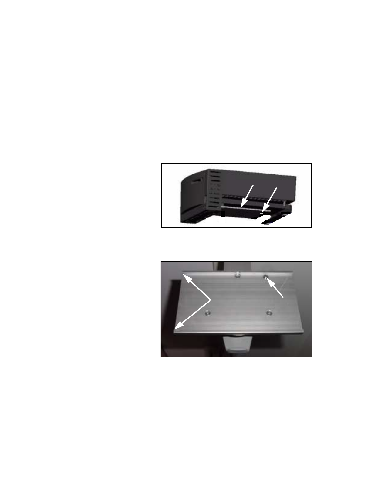
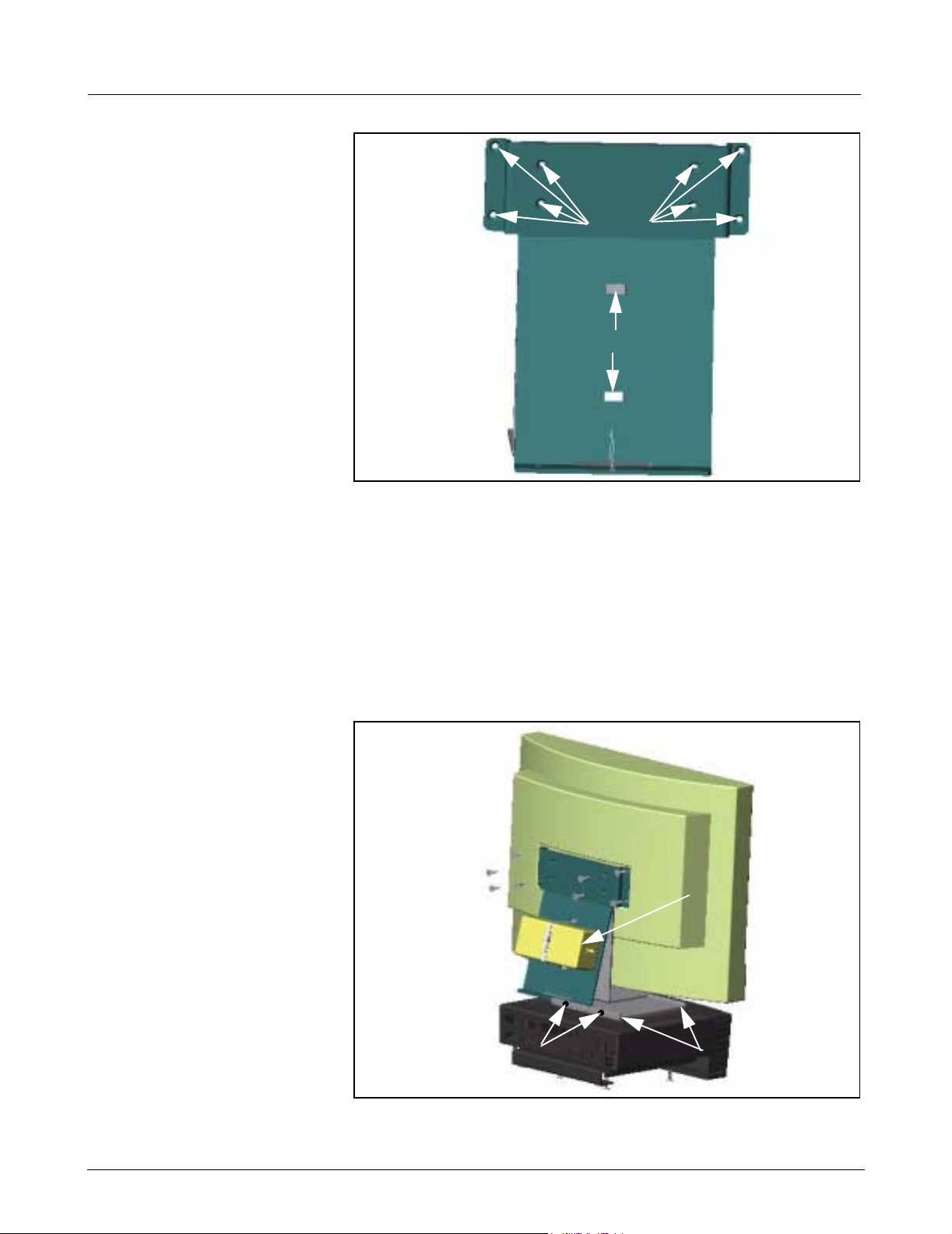
Figure 9-1 Moun0ting plate
2. Align mounting plate (a in Figure 9-1) on bottom of MDS to slots (a
in Figure 9-2) on left side of mounting bracket.
aaaa
Figure 9-2Mounting bracket
3. Pull down and hold spring loaded locking pin (s in Figure 9-2), and
slide in MDS to align hole on mounting plate (s in Figure 9-1) with
locking pin.
4. Release locking pin to secure mounting plate to mounting bracket.
Note: The locking pin snaps into place when properly installed.
ssss
5. Go to Section 10.
9.2 MDS Table Top Installation
14 Siemens Medical Solutions, EM-PCS, Danvers ASK-T962-04-7600
1. Set MDS on flat clean surface, and within close proximity of monitor,
keyboard, and mouse.
2. Go to Section 10.
InfExp_sm.fm/01-02/kaupp
INFINITY EXPLORER Field Service Manual
10Monitor Installation Do either a or b as appropriate:
a If installing optional Flat Screen to Medside Data Station, continue
to Section 10.1.
b If installing locally supplied monitor, go to Section 10.2.
10.1 Flat Screen Display (Art. No. 59 55 567 E531U)
dddd
aaaa
ssss
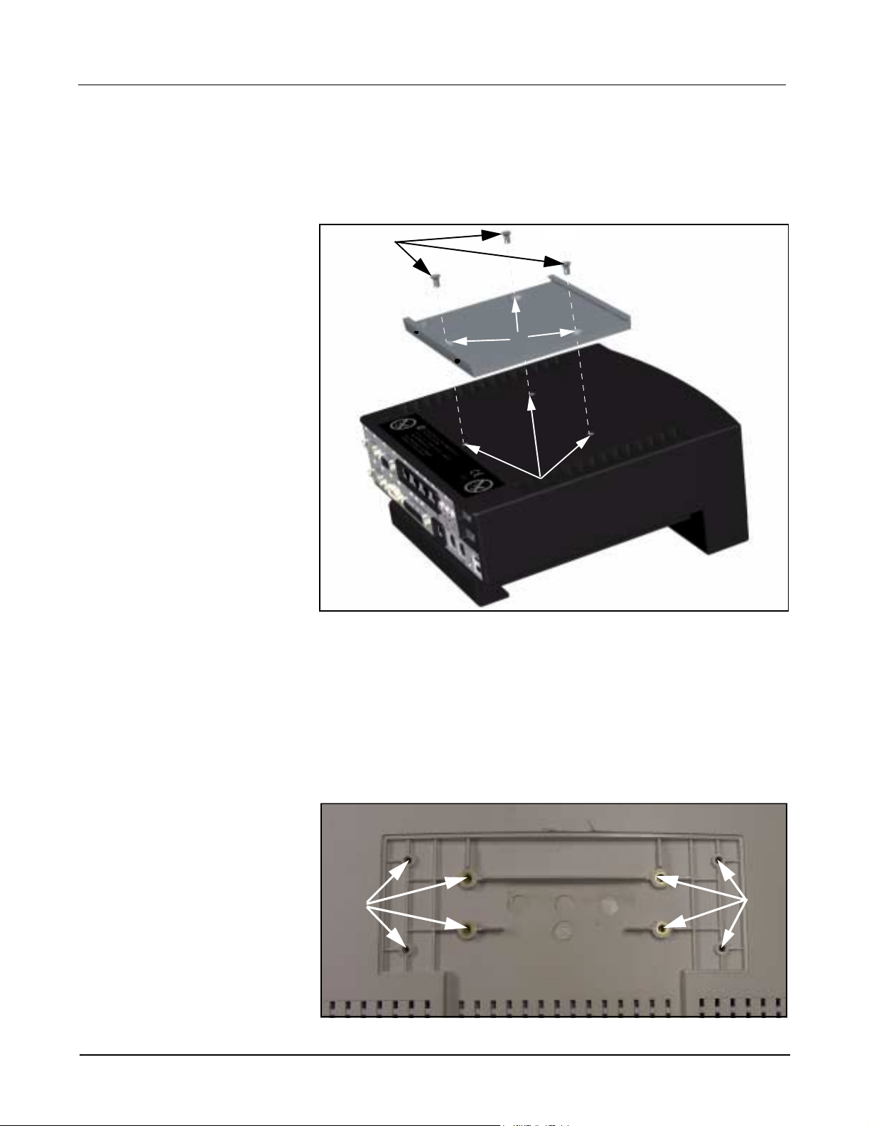
Figure 10-1MDS with mounting bracket
1. Set MDS upright on flat surface.
2. Remove and discard three plastic plugs from mounting holes on top
of MDS.
3. Align mounting bracket screw holes (a in Figure 10-1) to screw holes
on top of MDS (s in Figure 10-1).
Note: Mounting bracket and screws ship with flat screen display.
4. Insert and tighten 3 Phillips-head screws (supplied, d in Figure 10-1).
aaaa
Figure 10-2 Flat Screen Display Mounting Bracket Screw Holes(rear view)
ASK-T962-04-7600 Siemens Medical Solutions, EM-PCS Danvers 15
InfExp_sm.fm/01-02/kaupp
aaaa
Field Service Manual INFINITY EXPLORER
aaaaaaaa
ssss
Figure 10-3 Flat Screen Support Mount
5. Place flat screen display face down on clean surface.
6. Align eight support mount clearance holes (a in Figure 10-3) to
threaded holes on back of flat screen display (a in Figu re 10-2).
7. Insert and tighten eight Phillips-head screws (supplied).
8. Insert one cable tie (supplied) through back of each slot (s in Figure
10-3) to enable power supply to be secured to support mount.
9. Set power supply (a in Figure 10-4) between both slots on support
mount, and tighten cable tie to secure to secure supply to mount.
aaaa
aaaa
dddd
dddd
Figure 10-4 Flat Screen Display mounted to MDS
16 Siemens Medical Solutions, EM-PCS, Danvers ASK-T962-04-7600
ssss
ssss
InfExp_sm.fm/01-02/kaupp

INFINITY EXPLORER Field Service Manual
10. Set flat screen display upright with bottom of support mount aligned
to slots on mounting bracket (installed in step 2 and 3 above), and
slide mount into bracket (s in Figure 10-4 on page 16), so that mount
is positioned in center.
11. Insert and tighten two Phillips-head screws (supplied, d in
Figure 10-4) on rear of mounting bracket to secure flat screen display
in bracket.
12. Go to Section 11.
10.2 Locally Supplied Monitor
Refer to Installation instructions provided with monitor.
1. Set monitor on secure flat surface in close proximity to MDS.
2. Continue to Section 11.
11Keyboard, Mouse Do either a or b as appropriate:
a If installing keyboard and mouse to wall mount, continue to
Section 11.1.
b If installing keyboard and mouse on table top, go to Section 11.2.
11.1 Wall Mount 1. Set keyboard on shelf (refer to illustration on front cover), and slide in
side clamps to secure keyboard to shelf.
2. Set mouse on shelf (refer to illustration on front cover).
3. Go to Section 12.
11.2 Table Top 1. Set keyboard and mouse in close proximity to MDS.
2. Continue to Section 12.
12Connecting Devices 1. Insert and tighten 15-pin video cable from monitor into video out
connector (s in Figure 12-1 on page 18) on rear of MDS.
2. Plug Keyboard cable into keyboard connector (J in Figure 12-1) on
rear of MDS.
3. Plug mouse cable into mouse connector (H in Figure 12-1) on rear of
MDS.
4. Plug power cord from monitor into hospital grade outlet. (If using flat
screen monitor connect power cable from 12V DC power supply into
back of monitor, and then plug in power cord from power adapter into
hospital grade outlet).
5. Plug power connector from MDS AC power adapter into Power In
connector (j in Figure 12-1) on back of Medside Data Station, and
then plug power cord from AC adapter into hospital grade outlet.
6. Continue to Section 12.1.
ASK-T962-04-7600 Siemens Medical Solutions, EM-PCS Danvers 17
InfExp_sm.fm/01-02/kaupp
Field Service Manual INFINITY EXPLORER
aaaa
llll
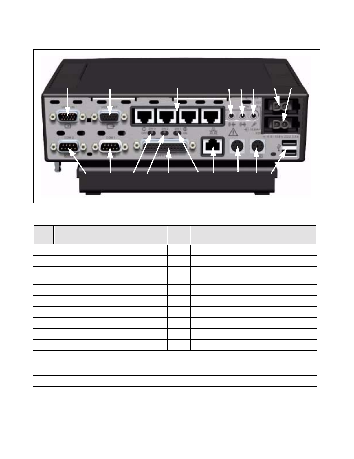
Figure 12-1MDS (rear view)
Table 12-1MDS Part Description
Item
No.
1 VIDEO IN / OPTIONAL COM 3/4 10 COM 1
Description
ssss
;;;;
AAAA
SSSS
DDDD
dddd
Item
No.
FFFF
Description
GGGG
ffffgggg
HHHH
hhhh
KKKKJJJJ
jjjj
kkkk
2 VIDEO OUT 11 BOOT ROM SELECT (default, switch to right)
3 *ETHERNET HUB (I
Repeater ports)
4 AUDIO OUT 13 PARALLEL PORT
5 AUDIO IN 14 PIEZO OVERRIDE (default, switch to right)
6 MICROPHONE 15 Hospital LAN Ethernet NIC (auto-negotiating)
7POWER IN 16MOUSE
8 POWER (future use) 17 KEYBOARD
9 COM 2 18 **USB
* Ethernet Hub does not auto-negotiate to a 10Mbs device. If a 10Mbs device is connected to the Ethernet
Hub all devices must be manually set to 10Mbs operation. If All ports are occupied by 100Mbs devices, no
manual settings are required. Consult your local IT department regarding manual settings of 10Mbs devices.
** USB is not supported by I
12.1 INFINITY Network Connections
NFINITY Network LAN
NFINITY EXPLORER
Connect INFINITY EXPLORER to INFINITY LAN as determined during preInstallation meetings (see I
to I
NFINITY LAN according to Section 12.1.1 or 12.1.2 as appropria te .
Note: Verify that INFINITY NETWORK Hardware has correct software
versions ( see Table 3-1 on page 1 ) installed before proceeding.
12 VIDEO OVERRIDE (default, switch to right)
NFINITY EXPLORER Scoping Document). Connect
18 Siemens Medical Solutions, EM-PCS, Danvers ASK-T962-04-7600
InfExp_sm.fm/01-02/kaupp
INFINITY EXPLORER Field Service Manual
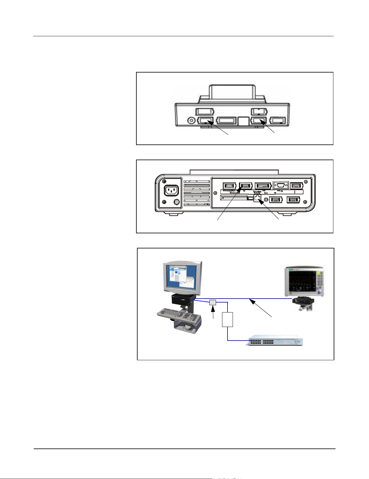
12.1.1 Single Point Connection If connecting to INFINITY LAN using a Single Point Connection, proceed as
follows:
Figure 12-2 IDS (rear view)
ssss
Figure 12-3 SC 8000 (rear view)
Zeus/MDS
ssss
aaaa
aaaa
SC7000/8000/9000XL
Wall
aaaa
Figure 12-4 INFINITY Network Single Point Connection
1. Connect MDS to INFINITY LAN switching hub as follows:
1.1) Plug one end of ethernet crossover cable (supplied) into one of
MDS repeater ports (see d in Figure 12-1 on page 18).
1.2) Plug other end of Ethernet crossover cable into Ethernet
coupler, a in Figure 12-4.
1.3) Plug shielded Ethernet patch cable from Ethernet coupler into
I
NFINITY LAN hospital wall box.
2. Connect MDS to Monitor as follows:
ASK-T962-04-7600 Siemens Medical Solutions, EM-PCS Danvers 19
InfExp_sm.fm/01-02/kaupp
Box
NFINITY LAN switching hub
I
ssss
Field Service Manual INFINITY EXPLORER
2.1) Plug one end of shielded Ethernet patch cable into one of MDS
repeater ports (d in Figure 12-1).
2.2) Plug other end of shielded Ethernet patch cable into Ethernet
port (a in Figure 12-2) on rear of IDS (if SC7000/SC9000XL) or
on rear of SC8000 (a in Figure 12-3). Installed Adv. Comm
Option II required.
Note: DirectNet connection to SC7000/SC9000XL monitors not
supported for installed monitor SW versions ≤VE2.
Also, note that INFIN ITY LAN RJ47 Wall Box Connector also connects
to I
NFINITY Switching Hub RJ47 Port via INFINITY LAN patch panel.
Install this connection during Horizontal Wiring phase of Installation.
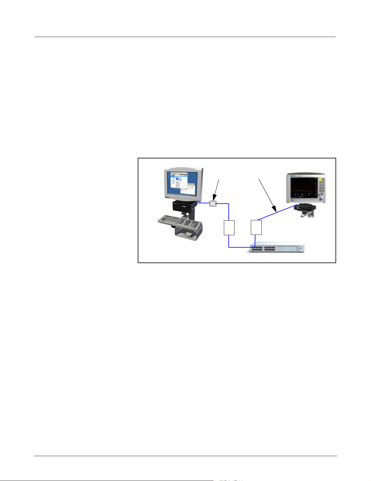
12.1.2 Dual Point Connection If connecting to INFINITY LAN using a Dual Point Connection, pr oceed as follows:
Zeus/MDS
aaaa
Figure 12-5 INFINITY Network Dual Point Connection
1. Connect MDS to INFINITY LAN switching hub as follows:
1.1) Plug one end of Ethernet crossover cable (supplied) into one of
MDS repeater ports, d in Figure 12-1.
1.2) Plug other end of Ethernet crossover cable into Ethernet
coupler, a in Figure 12-5.
1.3) Plug shielded Ethernet patch cable from Ethernet coupler into
I
NFINITY LAN wall box.
ssss
Wall
Box
NFINITY LAN switching hub
I
SC7000/8000/9000XL
Wall
Box
2. Connect Monitor to INFINITY LAN switching hub as follows:
2.1) Plug shielded Ethernet patch cable into Ethernet port (a in
Figure 12-2) on rear of IDS (if SC7000/SC9000XL) or on rear of
SC 8000 (a in Figure 12-3). Installed Adv. Comm Option II
required in SC 8000.
2.2) Plug other end of shielded Ethernet patch cable into INFINITY
LAN wall box.
Note: DirectNet connection to SC7000/SC9000XL monitors not
supported for installed monitor SW versions ≤VE2.
Also, note that INFIN ITY LAN RJ47 Wall Box Connector also connects
to I
NFINITY Switching Hub RJ47 Port via INFINITY LAN patch panel.
Install this connection during Horizontal Wiring phase of Installation.
20 Siemens Medical Solutions, EM-PCS, Danvers ASK-T962-04-7600
InfExp_sm.fm/01-02/kaupp

INFINITY EXPLORER Field Service Manual
I
NFINITY EXPLORER / MDS
aaaa
Wall
Box
Hospital LAN Repeater
Figure 12-6 Hospital LAN Connection
12.2 Hospital Network Connections
Plug one end of Ethernet Patch Cable into Hospital LAN RJ45 connector
(G in Figure 12-1 on page 18) on rear of MDS, and then plug other end of
cable into Hospital LAN RJ47 Wall Box Connector (a in Figure 12-6)
Note: Hospital LAN RJ47 Wall Box Connector also connects to RJ
47 Port at Hospital LAN Repeater Hub Patch Panel. This connection
is installed during Horizontal Wiring phase of Installation process.
12.3 Optional Video Cable Connect optional video cable (Art. No. 74 90 290 E530U) as follows:
Connect cable to monitor using procedure of either Section 12.3 .1 or
Section 12.3.2 below as appropriate:
12.3.1 Connecting to a SC 7000 or
SC 9000XL Patient Monitor
12.3.2 Connecting to a SC 8000
Patient Monitor
Plug one end of video cable into X5 on rear of IDS (s in Figure 12-2), and
then plug other end of cable into Video In (a in Figure 12-1) on MDS.
Plug one end of video cable into X5 on rear of SC8000 (s in Figure 12-3),
and then plug other end of cable into Video In (a in Figure 12-1) on MDS.
13Syngo Configuration INFINITY EXPLORER network configuration is completed using the INFINITY
E
XPLORER Syngo Service User Interface (UI). Network configuration
through the I
Key (password). When ordering a replacement Service license key refer to
Table 6.2 on page 5 of this Document for required information and then
contact TSS Danvers or TSS Solna with this information.
Note: Configuration information provided in this Manual is intended
for use with a previously installed system only. Refer to Hardware
Installation Instructions, ASK-T972-xx-7600, to install a new
system.
NFINITY EXPLORER Syngo Service requires a Service License
For the purpose of clarification, special text in this document is described below:
Bold Characters text that is to be typed by the User.
Character a space required between typed characters.
^
Italic Characters a selection that is required by the User.
ASK-T962-04-7600 Siemens Medical Solutions, EM-PCS Danvers 21
InfExp_sm.fm/01-02/kaupp
Field Service Manual INFINITY EXPLORER
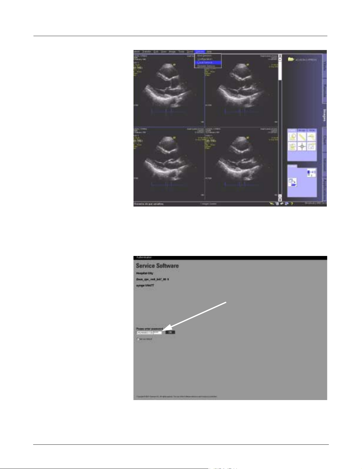
13.1 Syngo Service Window
Figure 13-1Infinity Explorer User Interface (UI)
1. Boot MDS to INFINITY EXPLORER User Interface (UI), and select nonPatient Monitoring tab.
2. Select Options at top of Infinity Explorer UI, and then select Local
Service (see Figure 13-1).
aaaa
Figure 13-2 Syngo Service (Service Menu)
3. Enter Syngo license key in blank boxes (a in Figure 13-2), and then
click OK to bring up Syngo Service Home Menu screen.
22 Siemens Medical Solutions, EM-PCS, Danvers ASK-T962-04-7600
InfExp_sm.fm/01-02/kaupp
INFINITY EXPLORER Field Service Manual
Note: A Syngo license key is comprised of two separate sets of
alpha-numeric codes. The first alpha-numeric code is 14 characters
in length and the second alpha-numeric code is six characters in
length. Type the first alpha-numeric code in the first box, and then
type the second alpha-numeric code in the second box. If the user
selects “Set as default” box, then next time Syngo service is
accessed, only second alpha-numeric code must be typed.
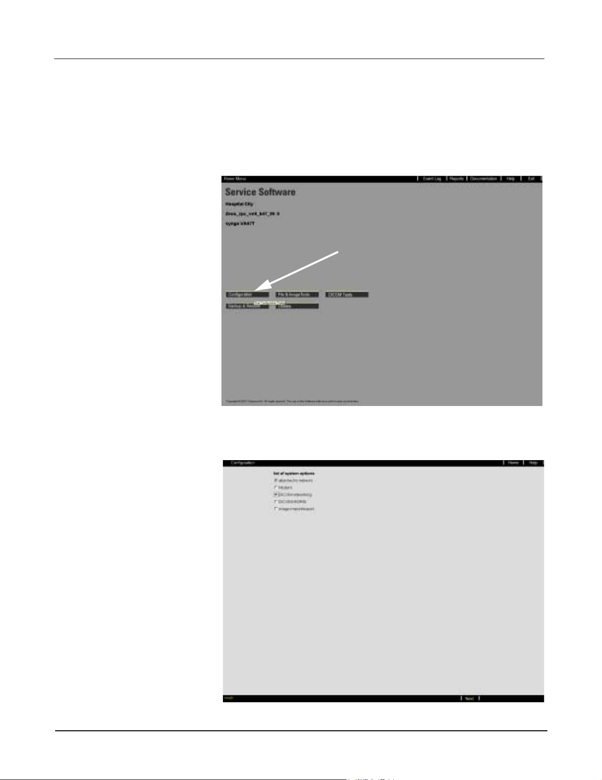
aaaa
Figure 13-3 Syngo Service (Home Menu)
4. Click on Configuration button (a in Figure 13-3) to bring up Syngo
Service Options List screen.
Figure 13-4 Syngo Service (Options List)
ASK-T962-04-7600 Siemens Medical Solutions, EM-PCS Danvers 23
InfExp_sm.fm/01-02/kaupp
Field Service Manual INFINITY EXPLORER
5. Check boxes to select options according to following table.
Table 13-1Options List
Attached to network Select
Modem Do Not select
DICOM networking Select if connecting to a DICOM Server.
DICOM HIS/RIS Do Not select
Image import/export Do Not select
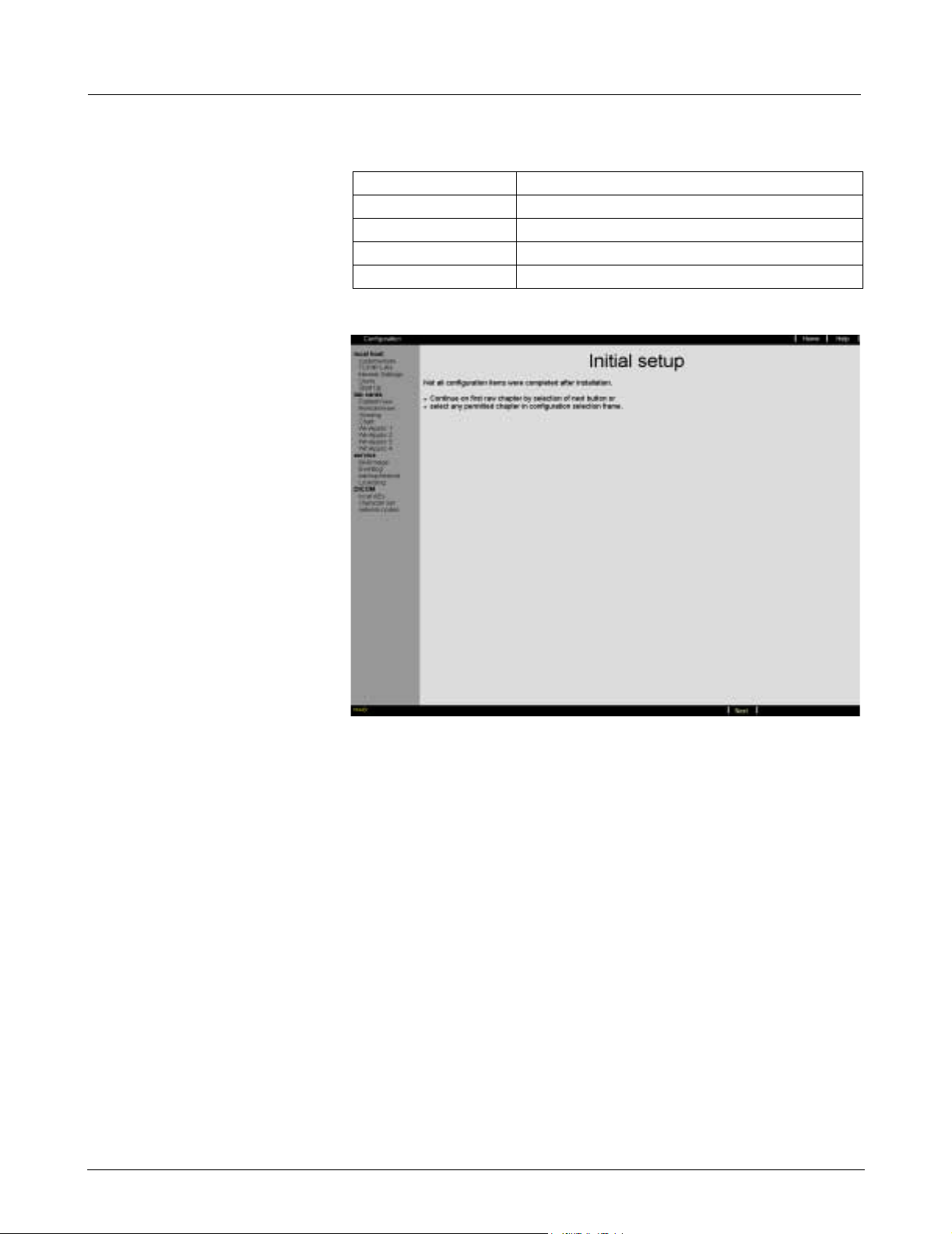
6. Select Next in footer to bring up Initial Setup screen.
Figure 13-5 Initial Setup Screen
Note: The initial setup screen appears only the first time Syngo
Service configuration is selected. During Syngo configuration
process, left side of configuration window labels sections that
must be configured. Initially, all section labels are displayed in black
text. Once a section has been configured, the label for that section
is displayed in yellow text. The right side of the screen describes
the current configuration section and the data required to complete
this section. Information needed to complete each section is
displayed in page(s) prior to section requiring user interaction. All
configuration sections must be completed the first time in
sequential order from beginning (top) to end (bottom).
If configuration changes are required after INFINITY EXPLORER
configuration has been completed and the system has been
rebooted, the user can select the section label and edit the
configuration of that label without having to enter another label.
7. Select Next in footer to bring up Configuration Menu screen.
Note: First menu item of local host configuration “Customer/Site”
is automatically selected.
24 Siemens Medical Solutions, EM-PCS, Danvers ASK-T962-04-7600
InfExp_sm.fm/01-02/kaupp
 Loading...