

Page 1
Siemens Practices
Installation Series
A30808-X5130-8120-1-8928
Issue 1, May 1986
:
1
1
’
!
Issued by Office Systems Group
5500 Broken Sound Boulevard
Siemcns Information Systems, Inc.
N.W., Boca Raton,
--___________-
Florida 33431
(305) 994-8100 l Telex: 515052
----- -
..-
-----
Printed in U.S.A.
Page 2
SATURN
Installation Test Procedures Issue 1, May
IIE
EPABX
A30808X5130-8120-1-8328
1906
SECTION
l.CO INTRDCUCTlON
Purpose ..................................
scope ....................................
Siemens SATURN
Siemens Customer Support Services. ...........
2.00
PREP/%KGXIY
Cener21.
Test Equipment Required. ...................
Handling Precautions for
PC6
Initial Visual Inspection Procedures
3.CO
GROUND TESTS ..........................
General.
System Ground Test. ........................
Shelf Ground Continuity Test. .................
4.00 POWER-UP TESTS ........................
Genera I..................................
Power-Up/Output Voltage Tests. ...............
5.00
OPERATING PROGRAM
General.
Loading
Inputting CMU
&CO
ON-FINE
General.
Connection of Maintenance Phone
MDF Cross-Connecting
System Diagnostic Tests; ....................
.................................
MOS Integrated
Removal and Replacement Guidelines.......
..................................
..................................
Operafing Dis!~.
..................................
and Modem ..............................
............;.............
IIE
Practices ................. l-l
ACTIVITY ...................
PC&
Circuiis.
with
....................
LOAD!NG
Data
DlAGrGxTlC
.....................
to
Floppy
Disk. ............
TESTS ...............
Prccedures.
..............
............
............
PAGE
.1-l
2-1
2-1
2-l
2-l
2-1
2-1
3-l
3-l
3-1
3-1
4-l
4-1
4-l
5-1
5-1
5-l
5-l
6-3
6-12
l-l
1-l
l-l
6-l
6-l
6-1
6.02 Single -Line Telephone Cross-Connections
Using SLMA
6.03 Single
6.04 Siemens Digital
6.05 SATURN Attendant Console Cross-Connections
6.06 CO and
6.07 Two-Wire (Type I) E&M Trunk
6.08 Four-Wire
6.09 Two-Wire
6.10 Four-Wire
6.il
Recorded
6.12 Code
6.13 Dial Ciciation
6.14 Music-en-Hold Cross-Connections Using
6.15 Music-on-Ho!d Cross-Connecticns Using
6.16 Paging With Answerback Cross-Connections 6-10
6.17 Paging Without Answerback Cross-Connections. . 6-10
6.18 Universal Night Answer (UNA) Cross-Connections
6.49 Attendant
620
6.21 Siemens JR-DYAD
-Line
Using
Using SLMD PCB. .
Vacant Number Intercept, and ACD
Announcement
Cross-Connections . . 6-8
TMBA4
SLMAISLA16
Button
Siemens
Sequence . . . . . . . . . . . . . .
Depression
Telephone Cross-Connections
CID
(T;lce
I)
_.
(Type II)
(?ype
II)
Anncuncement
Ca!ling
(With or Without Answerback)
PCB . . . . 6-9
PCB . . . . . . 6-9
Conscie
DYIiD Te!ephono Buttcn Ccpressicn
PCB
. . . 6-3
SLAi6
Teiephone
Trunk Cross-Conneciions .
E&M
Trunk Cross-Connections
E&M Trunk Cross-Connections . 6-6
E&M
Trunk Cross-Connections . 6-7
(DID and Tie Trunk
Service)
(DTMF)
Keypad and
Depiassion
Te!ephone
Sequence
PCB
Cross-Connections
Cross-Connec?ions
Cross-Connections 6-7
Cross-Conneciions. 6-8
Fcaturo
Ssquonce
Euitcn
. . 6-23
6-3
63
G-4
E-5
G-5
G-S
E-11
G-:3
6-21
7.CO
INSTALLATION TEST
General
...................................
PRCCEDURES CHEC#L!ST
l=lGURE
2.00 Signal
2.01 Signal Cable Distribution for the SATURN
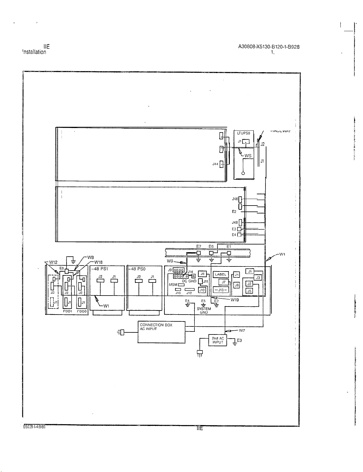
2.02 Power/Ground Distribution for the SATURN
2.03 Power/Ground Distribution for the SATURN
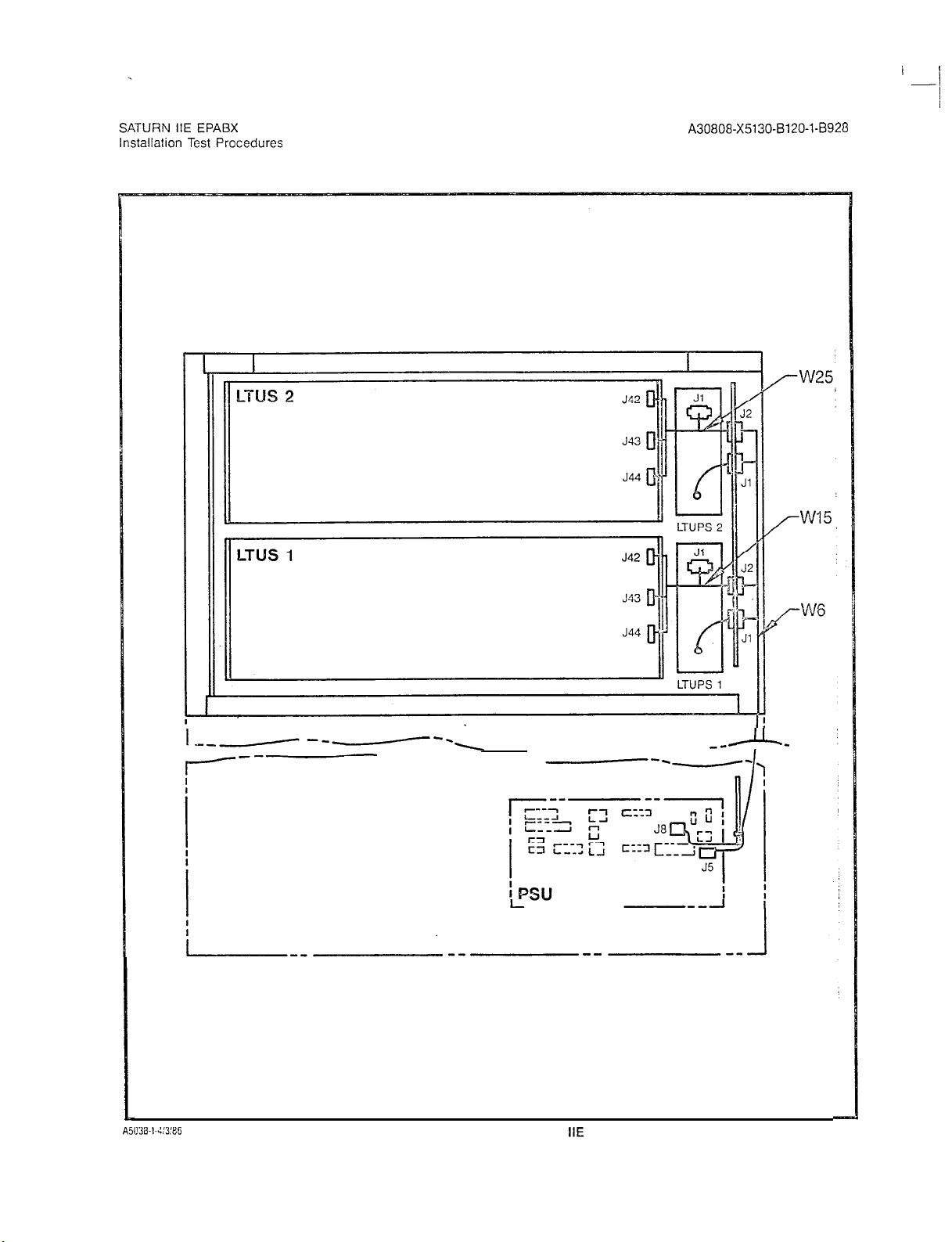
3.00 System Ground Test Connections
3.01 Shelf Ground Continuity Test Connections.
4.00 Location of Input Voltage Connectors on
4.01 Location of Input Voltage Connectors on
5.00 Floppy Disk and Storage Envelope .........
5.01 Power System Unit (Front View).
5.02 Floppy Disk Loading Procedures.
5.03
6.00 Maintenance Phone and Maintenance-Related
6.01
Cab!e
System (Basic Cabinet). ................
System (Expansion Cabinet).
System (Basic Cabinet). ................
System (Expansion Cabinet) .............
Distribution for the SATURN
............
..........
Basic Backplane. .....................
LTU Backplane .......................
...........
CIOP
Printed Circuit Board ...............
Cress-Connections ....................
Modem
Cross-Connections ...............
..........
IIE
IIE
IIE
IIE
...
PAGE
.
. .
.
7-l
7-l
2-4
2-5
2-6
2-7
3-2
3-3
4-5
4-6
5-l
5-4
5-5
5-6
6-2
6-z
1.00 Mnemonics Used in This Practice .............. l-l
2.CO
PCB and
2.01 Visual
3.00 System Ground Test. ........................
3.01 Shelf Ground Continuity
4.00 Power-Up/Output
5.00 Loading Procedures fcr Operating Disk. .........
5.01
CIOP
5.02 LED Display Values for Leading Errors
6.00 Tone Generator Test
6.01 Tone
6.02 DTMF
6.03 Station Line Test. ..........................
6.04 DTMF Pad Test
6.05 Console Test
6.06 Attendant Console Displayable Characters. ......
6.07 Siemens Digital Telephone - DYAD Button Test 6-20
6.08 Siemens Digital Telephone - JR-DYAD
6.09 Siemens
6.10 Siemens Digital Telephone Displayable
6.11 Outgoing Trunk Test .
6.12 Placing Circuit(s) In-Service
6.13 Taking Circuit(s) Out-of-Service
7.CO Insta!lation
Powar
Inspeciion
DIP
Genera:or
Receiver
Button Test . . . . .
Characters . .
Supply Removal
...........................
Test
Voitnge
Test .................
Swiich
Settings ....................
........................
Test
I\!umbers
Test ........................
............................
...............................
Digiial
Telephone
Test Procedures Checklist
Guidelines
..................
..........
................
-DYAD
Display Test
.....
2-2
2-3
3-l
3-1
4-l
5-2
5-3
5-4
6-13
G-i3
G-14
6-14
6-15
6-16
6-19
G-22
6-24
6-25
6-26
6-27
6-27
7-l
Page 3
SATURN
IIE
EPABX
installation Test Procedures
A30808-X5130-0120-l-0928
Issue 1, May
1986
.
1.01
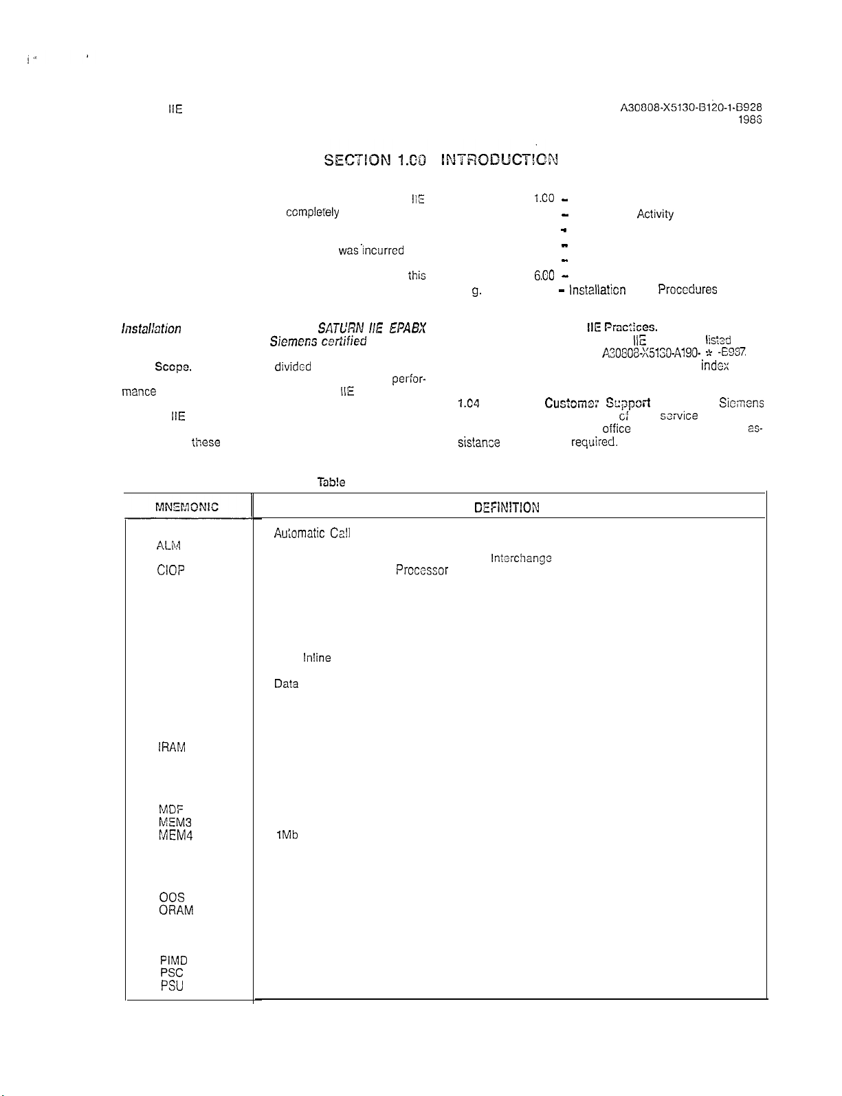
Purpose. The equipment comprising the SATURN
(SATURN Ii-Expanded) System is
compleYely
tested at the fac-
IiE
tory prior to shipment. The inspections and tests covered in
this practice verify that the EPABX equipment has been
properly installed; ensure that no damage
wasIncurred
during transit; and confirm that the sysiem is completely operational. Table 1.00 defines the mnemonics usedthroughout
ihis
practice.
CAUTION
lnstalbtion
must be performed only by
1.02
tions which are presented in the sequential order of
mance
test procedures on the
SATL’RN I/E EPABX
Siemer;s cetiified
Sccpe.
This practice is
divided
into the following sec-
after initial installation of a SATURN
personnel.
IIE
System. When
per-for-
additional equipment is installed to an existing and active
SATURN
IIE
System, it is the responsibility of craft person-
nel to determine the sequential order of the test procedures
contained in
ACD
ALiVl
tihese
sections.
TaS!e
Au;omaiic Cafl
Alarm
1.00 Mnemonics Used in This Practice
Disiribution
ASCII American Standard Code for Information
CIOP
Controller/Input-Ouiput
Prccessor
CMU Customer Memory Update
co Central Office
CONF Conference Module
COT
Central Office Trunk
DCI Data Communication Interface
DID Direct Inward Dialing
DIP
DP
DTE Da?a
DTMF
EIA
EPABX
Dual
lnline
Package
Dial Pulse
Terminal Equipment
Dual Tone Multifrequency
Electronics Industries Association
Electronic Private Automatic Branch Exchange
FDD Floppy Disk Drive
IRAM
LTU
LTUPS
Input Random Access Memory
Line/Trunk Unit
Line/Trunk Unit Power Supply
LED Light-Emitting Diode
MCA Memory Control and Attenuation
MDF
MEM3
MEM4
MOS
Main Distribution Frame
25Gkb Memory
1Mb
Memory
Metal Oxide Semiconductor
MRA Material Return Authorization.
MSM
MTCE
00s
ORAM
PABX
Memory Support Module
Maintenance
Out-of-Service
Output Random Access Memory
Private Automatic Branch Exchange
PCB Printed Circuit Board
PEN
PIMD
PSC
PSU
Port Equipment Number
Premium Instrument Module Digital
Parallel/Serial Converter
Power Supply Unit
a. Section
b. Section 2.00 - Preparatory
l.CO -
Introduction
Activiiy
c. Section 3.00 - Ground Tests
d. Section 4.00 - Power-Up Tests
e. Section 5.00 - Operating Program Loading
-
f. Section
g.
Section 7.00 -
On-Lina Diagnostic Tesis
6.80
lnstallaticn
Test
Procedures
Checklist
7.03
Siemens SATURN
numbers and dates for the SATURN
IIE Prac:iccs.
IIE
The practices, issue
EPABX are
lists3
in the
Practices Documentation Index A.30808~X5130-AlgO- * -E987 Al-
ways refer to the !aiest issue of the application
indcx
to ob-
tain the latest issue number of a practice.
724
Siemens
maintains a nationwide network
tact the Siemens regional
sistance
that may be
Cus;oma: Sqpsrt
cf
oifice
requked.
Services.
field
service
Sicrnons
offices. Con-
for any engineering
es-
DEFiN1TfON
lntarchange
i-i
Page 4
SATURN
Installation Test Procedures
IIE
EPABX
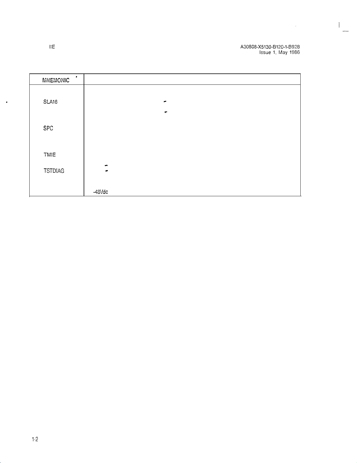
Table 1.00 Mnemonics Used in This Practice (Continued)
[\fiNEMDNIC *
RAUP Remote Access Unit/Ports
.
RGEN Ring Generator
S-416
SLMA
SLMA-S
SLMD
SMXTG
SPC
SPG
TMBA-2
TMBA-4 Four-Wire E&M Trunk
TMBM
TMIE
TMS
TSTAPP
TSTDIAG
TTY
UNA
ZUNA Zoned Universal Night Answer
-48PS
Subscriber Line Module Analog - 16 lines
Subscriber Line Module Analog
Subscriber Line Module Analog - Station
Subscriber Line Module Digital
Signal Multiplexer/Tone Generator
Stored-Program-Controlled
Single Point Ground
Two-Wire E&M Trunk
Central Office Trunk
Direct Inward Dialing Trunk
Transmission Measuring Set
Test - Apparatus
Test - Maintenance Diagnostic
Teletypewriter
Universal Night Answer
-48Vdc
Power Supply
DEFINITION
l-2
(2 pages)
Page 5
SATURN
Installation Test Procedures Issue 1, May 1986
2.01
quired to perform the installation test procedures, handling
precautions for Printed Circuit Boards
ide Semiconductor (MOS) integrated circuits, guidelines for
removal and replacement of
initial visual inspection procedures.
2.02 Test Equipment Required. The following test equipment is required to perform the procedures contained in this
practice:
IIE
EPABX
General. This section describes the test equipment re-
(PCBs)
with Metal Ox-
PCBs
and powei supplies, and
a. Digital Multimeter. A digital multimeter of
mercial quality with an accuracy of + 1.0% or better.
The digital multimeter is used to perform the ground
tests and output voltage tests.
b.
Maintenance Test Phone. For both Dial Pulse (DP) and
Dual Tone Multifrequency
test set or a single line
(MTCE PHONE) is provided on the front
PSU for
equipped with a modular plug. When the maintenance
test phone is not equipped with a modular plug, a station appearance can be used via the Main Distribution Frame
to perform the on-line diagnostic tests.
c. Data Service Terminal. A Keyboard-Send-Receive
conneciing
(MDF).
The
(KSR) daia terminal equipped with a standard ASCII
keyboard and an EIA RS-232C interface (Silent 700
Series - Model 743 KSR - Texas Instruments, or
equivalent). The data service terminal is used to input
installation dependent data (i.e., system data base) into
system memory when the standard data base format
is supplied with the SATURN
(DTMF)
systems, a lineman’s
te!ephone.
the maintenance test phone when
mainienance
IIE
System.
gocd
com-
A modular jack
panal
of the
test phone is used
A30808-X5130-B120-l-8928
d. -Transmission Measuring Set. A transmission measur-
ing set (TMS) used to measure the transmission quality of a trunk or station (Hewlett Packard HP-355iA or
equivalent). Refer to the manual On-Line
Tests, Outgoing Trunk Test and Station Line
2.03 handling Precautions for
ed
Circuiklt
with MOS integrated circuits free themselves from electrostatic
charge by touching a grounded cabinet frame before handling
such
observe this practice may result in damage to
due to electrostatic discharge.
lirazardous
Be extremely careful when
incjtroubleshooting
panel(s) removed.
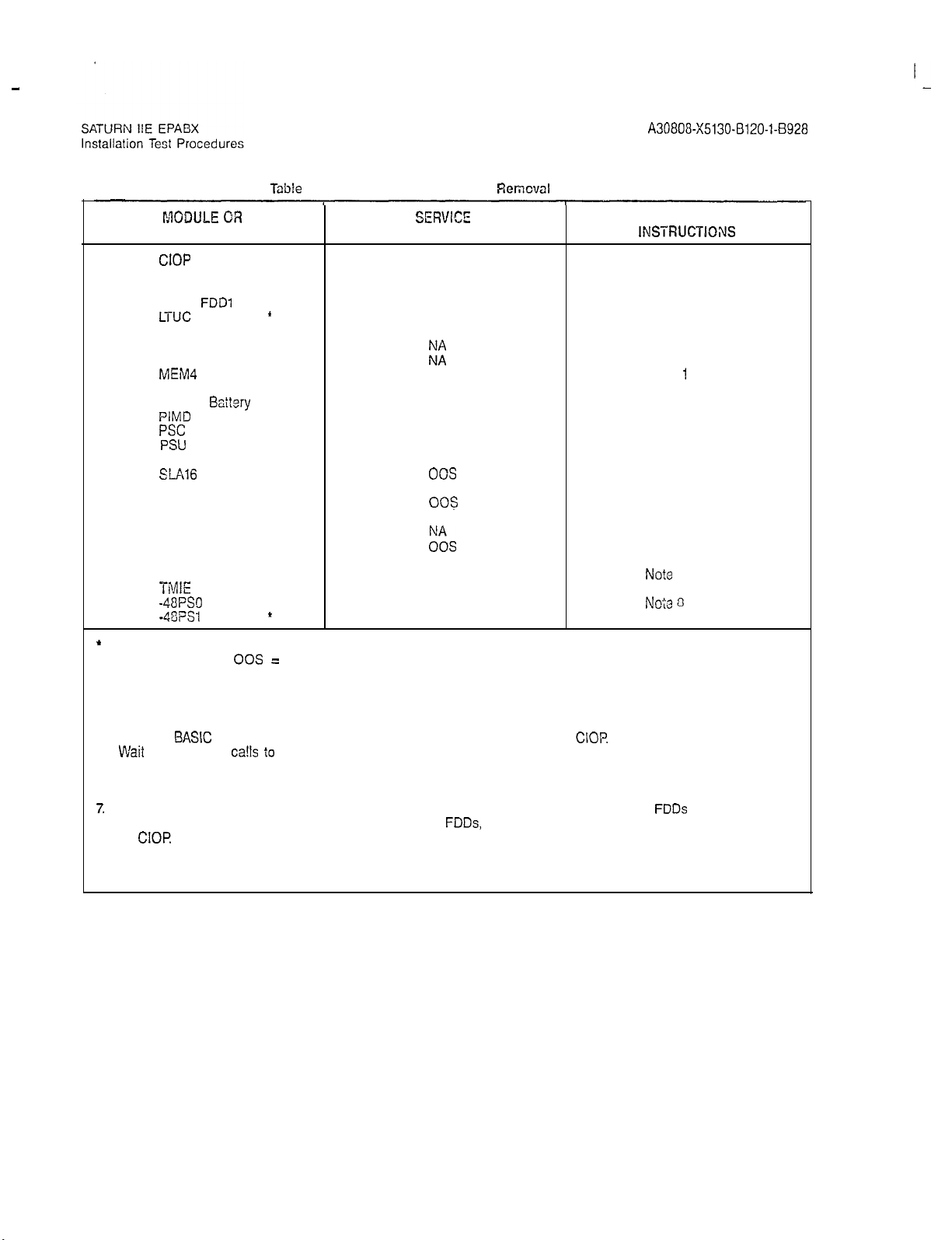
2.04
instances during testing, the corrective action for a procedure
in which the proper verification was not obtained requires that
a PCB or a power supply be removed and replaced with a
spare.
served when removing and
plies in an active
2.05
spection procedures contained in
to ensure that the equipment comprising the SATURN
tem has been properly installed and configured to meet the
installation requirements. Before proceeding
spections, the front, rear and side panels of the
be removed to
is important that craft personnel handling
PCEs,
or by wearing grounded wrist straps.
WARNING
voltages
PCB Removal and
Tablo
2.00 provides the guidelines that
lnifial Visual kspactizn Procedurx.
exist r&h.%
procedures
sysicm.
allcw
thorough inspection of the equipment.
PCBs wifh MCS Integmt-
the
eqo&ment
perr”orming fcsa-
with
P,ep!acemenZ Guide%%
rep!acing PCBs
Tab!e
2.01 must be
DiagnostiC
Failur:,
MO3 PCBs
cabins?.
the
oquipmcr;t
shou!d
and
powor SI:;X-
The
visu’al
psrfcrmcd
wiih
the visual in-
cabinei should
Tosl.
FCBs
to
In many
be
o!)-
in-
ItE
Sys-
2-1
Page 6
-
Table
2.00 PC3 and Power Supply
I’AODIJLE OR SERVEC”
UNIT
CIOP
STATE
NA
CONF . NA
DTMF 00s
FDDO,
FDDl
LTUC
LTUPS
f
l
NA
NA
NA
MCA
MEM3
MEM4
MSM
MSM
PIMD
PSC
PSU
RAUP
SLAl6
l
Baitery
l NA
kz
NA
NA
00s
NA
NA
NA
00s
SLMA-0 00s
SLMA-S
003
SLMD 00s
SMXTG
TMBA-2
TMBA-4
TMBM
TMIE
-48PS.l
-48PSt
f
ES
00s
00s
00s
NA
NA
Remcval
Guidelines
A30808-X5130-8120-l-8928
Issue 1, May 1986
SPECIAL
INSTRUCTKWIS
Notes 1 and 2
Notes 1 and 2
Note 3
None
Note 4
Note 5
Notes 1 and 2
Notes 1 and 2
Notes 1 and 2
Note 1
Note 6
Note 3
Notes 1 and 2
Note 7
Notes 1 and 2
Note 3
Note 3
Note 3
Note 3
Notes 1 and 2
Note 3
Note 3
No?e
3
Note 3
Note 8
Noie 3
*
Optional depending upon customer/system requirements.
NA = Not Applicable;
00s =
Out-of-Service
Notes:
1.
System outage (halts call processing). Set BASIC PS circuit breaker on PSU to off.
2.
Open FDD and remove floppy disk before removing PCB. After new PCB is inserted, reinsert floppy disk, close
FDD, set
3. VVait
4.
Removal places one-half of ports in shelf out-of-service.
5.
Before removal, set related LTUPS circuit breaker on PSU to off. Removal places all ports in shelf out-of-service.
6.
Battery may be replaced with power applied to system.
7.
System outage (halts call processing). Before removal, set all circuit breakers to off, open
py disks. After replacement, reinsert floppy disks, close
on
8.
Set related circuit breaker on PSU to off. May halt call processing depending upon system configuration and
BASK
for in-process
CIOR
PS circuit breaker on PSU to on, and press reset switch on
ca!ls
i0
complete.
FDDs,
set circuit breakers to on, and press reset switch
CIOP
FDDs
and remove flop-
traffic. If there are two -48Vdc power supplies (where system includes an Expansion Cabinei), the remaining supply may have sufficient capacity to support system operation.
2-2
Page 7
I
.-
SATURN
Installation Test Procedures
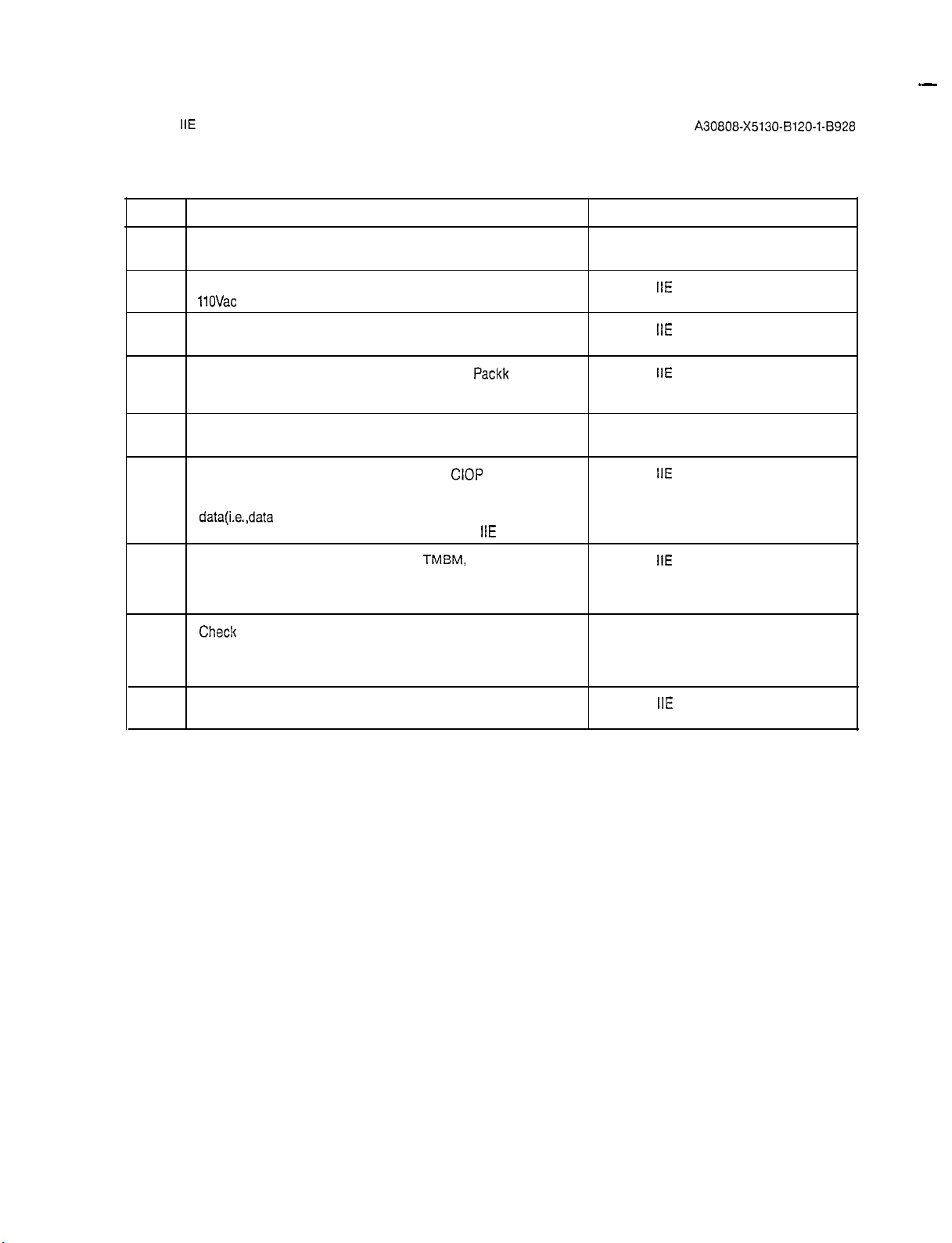
STEP
1
2
3
4
5
6
7
IIE
EPABX
Check that the cabinet ac power cord is not connected to an
electrical outlet.
Check that the -48Vdc power supply is strapped for SATURN
11OVac
or 22OVac. Procedures Practice (Section 4.00)
Check that all circuit breakers on the Power System Unit SATURN
(PSU) are in the OFF position and fuses inserted. Procedures Practice (Section 4.00)
If the MSM is installed, check that the Battery
connected but inserted into corresponding position. Also Procedures Practice (Section 4.00)
check that the PSU is strapped for MSM operation.
Check that each PCB in the system is withdrawn from its
backplane connector.
Check that the DIP switch settings for the
to meet the operating characteristics of the particular data Procedures Practice (Section 4.00)
service terminal to be used to input the installation-dependent
data(i.e.,data
data base format is supplied with the SATURN
Check that each trunk-type PCB (i.e.,
and/or TMBA-4) is properly strapped according to the Procedures Practice (Section 4.00)
operating characteristics of the trunk facility of the Central
Office (CO) or distant PABX.
base) into system memory when the standard
A30808-X5130-B120-l-8928
Table 2.01 Visual Inspection
VISUAL INSPECTION REFERENCE
IIE
EPABX Installation
IIE
EPABX Installation
Packk
is not SATURN
CIOP
board are set SATURN
IIE
System.
TMEM,
TMIE, TMBA-2 SATURN
IIE
EPABX Installation
IIE
EPABX Installation
IIE
EPABX Installation
Issue 1, May 1986
8
Chec!c
that the intercabinet signal and power/ground cabling Figures 2.00 through 2.03
arrangements are complete and all connectors are firmly seated according to the referenced illustrations (Figures 2.00
through 2.03).
9
Check that Berg Clips are on pins 27 and 28 of unused SATURN
signal cable connectors on basic shelf. Procedures Practice (Section 4.00)
IIE
EPABX Installation
2-3
Page 8
I
I
SATURN
,xtallation
IIE
EPABX
Test Procedures
A30808-X5130-B120-l-5928
Issue 1, May 1986
w3 w13
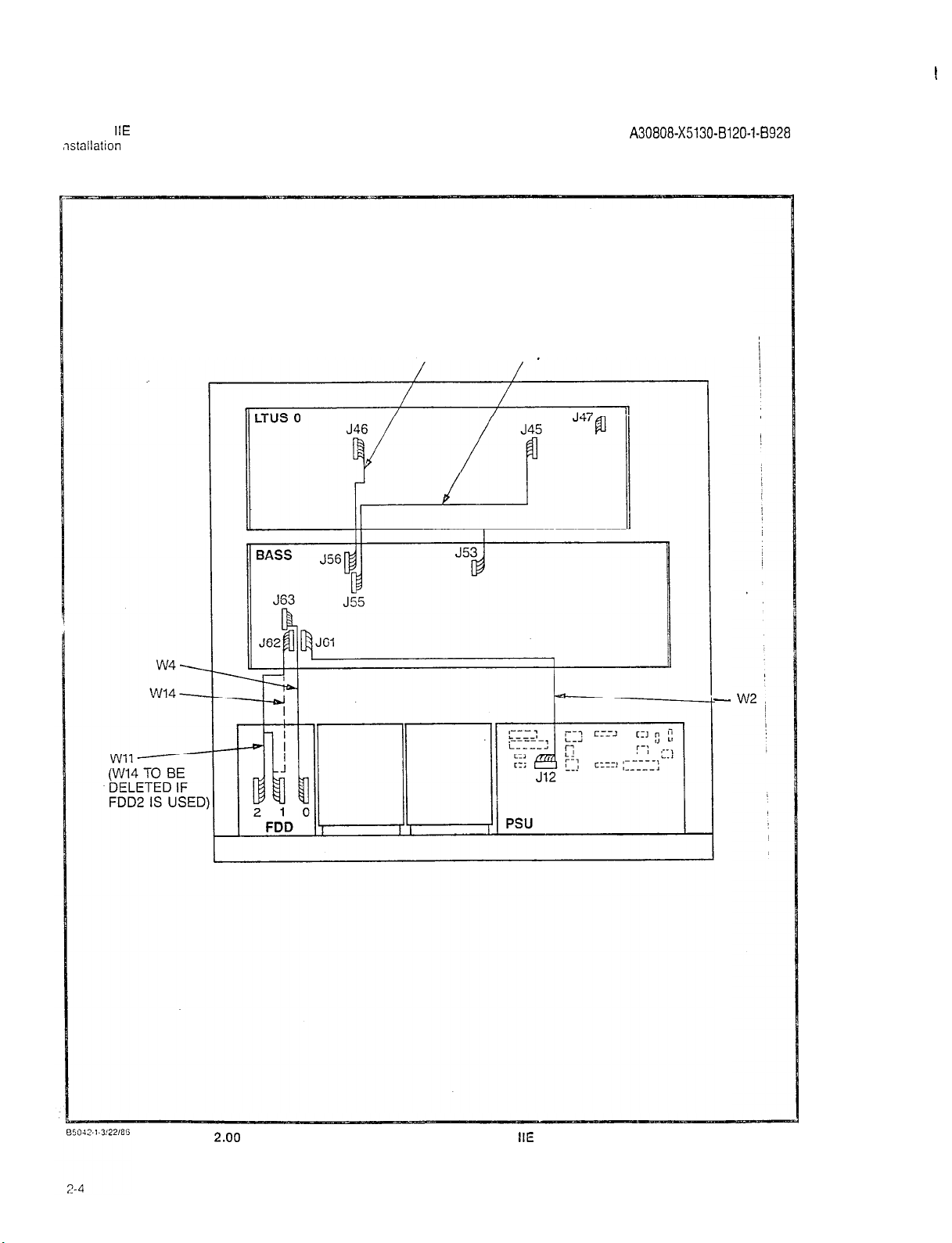
Figure
2.00
Signal Cable Distribution for the SATURN
IIE
System (Basic Cabinet)
-
Page 9
SATURN
Installation Test Procedures
IIE
EPABX
A30808-X5130-B120-l-8928
issue 1, May 1986
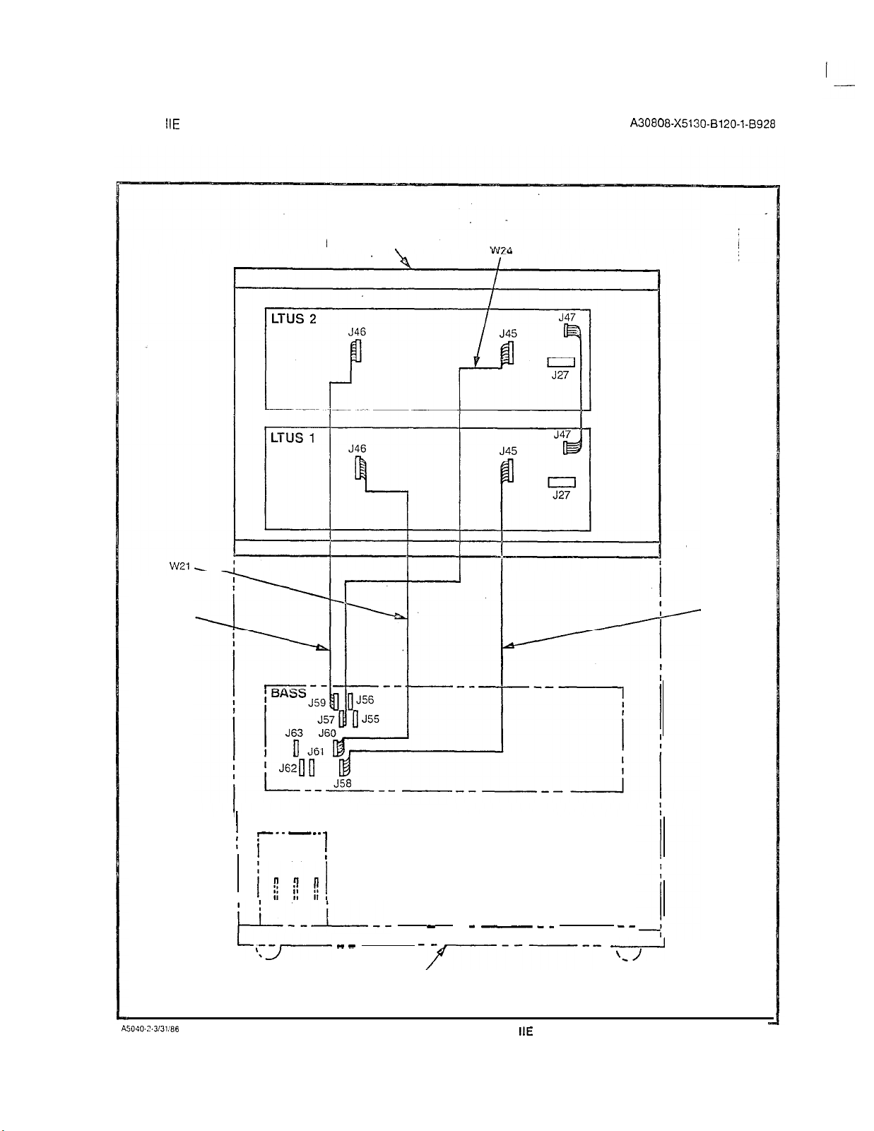
W23
EXPANSION CABINET
\
W22
A5040-2.313186
I
--- ---
: ]
,
i;wi!
i-L--i--
FDD
1
:
-
_-__
LiTJ-. - -
-r-----
BASIC CA&NET
Figure 2.01 Signal Cable Distribution for the SATURN
--
*
IIE
System (Expansion Cabinet)
2-5
Page 10
SATURN
tnstallation
IIE
EPABX
Test Procedures
A30808-X5130-8120-1-8928
Issue 1, May 1986
LTUSO
LINE TRUNK UNIT SHELF
BASS
BASIC SHELF
J42
J43
El a----
J46
J47
E2
r JP
L
Jl
05039.1..wmG
2-6
Figure 2.02 Power/Ground Distribution for the SATURN
IIE
System (Basic Cabinet)
Page 11
EXPANSION CABINET REF.
A30808-X5130-B120-l-8920
Issue 1, May 1986
A5U38-1-4:3:86
L
--M--e--\
----
------
BASIC‘CABINET REF.
Figure 2.03 Power/Ground Distribution for the SATURN
-----
IIE
System (Expansion Cabinet)
-,-,
2-7 (2-8 blank)
Page 12
SATURN
IIE
EPABX
Installation Test Procedures
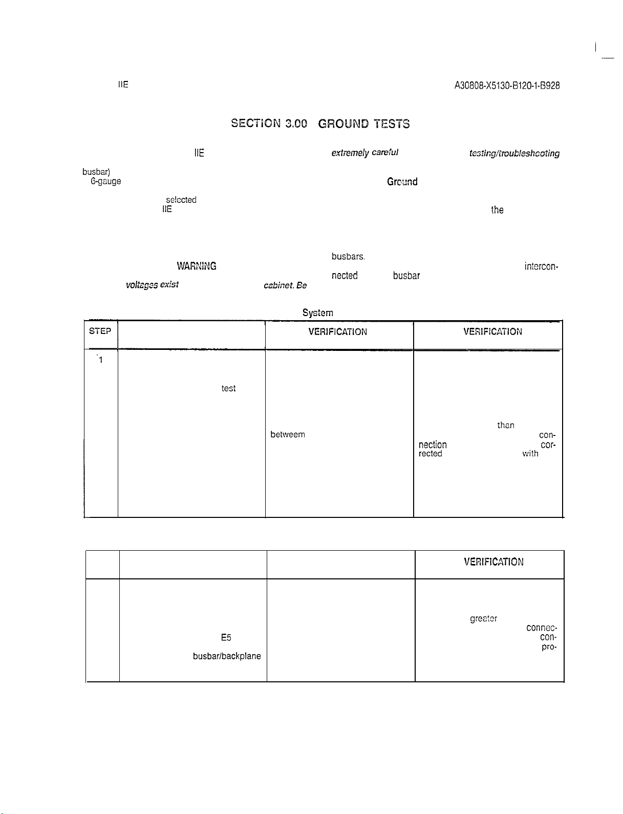
3.01
General. The SATURN HE System must be connected
to an earth ground (i.e., metallic cold water pipe or master ground
busbar)
in addition to the safety ground in the ac power cord.
A
G-gauge
(twisted copper wire) conductor should be connected between the grounding lug E5 located on the bottom of the
cabinet frame and the
snlccted
earth ground (refer to Section
3.00 in the SATURN HE EPABX Installation Procedures practice for details). The following tests must be performed to en-
extremely ca-ej’Ll
procedures with the equipment panel(s) removed.
3.02
System
Grcund
procedures indicated in Table 3.00, check that the earth
ground connections are secure and ground conductors are
firmly positioned on grounding lug E5 at
cabinet frame.
sure that proper earth ground connections have been
3.03
accomplished, and that ground connections within the cabinet
assembly have not been damaged or loosened during shipment.
WARNiNG
Hazardous
voltsgos txkt
within the equipment
csbinef. Ee
Shelf Ground Continuity Test. Each LTU shelf assembly within the cabinet assembly is grounded via two vertical
busbars.
Beiore proceeding with the test procedures indicated in Table 3.01, check that each shelf backplane is
netted
with the
busbar
position.
A30808-X5130-B120-l-8928
issue 1. May 1986
when performing
t~s%i~g/l’roubiesh~oting
Test. Before proceeding with the test’
ihe
bottom of the
flanges and adequately secured into
iniercon-
.l
2
3
4
STEP
1
Table 3.00
PROCEDURE
System
Ground Test
VERlFlCATlON
IF
VERlFlCATION
IS NOT OBTAINED
If connected, remove ac power cord
from commercial power outlet.
Short digital multimeter
tesi
leads
together and noie resistance of test
leads.
Set digital multimeter to lowest
resistance range and connect its
leads between the U-ground pin of the measured test lead resistance.
the ac power cord and the U-ground
socket in the commercial power
Resistance measured should be If a reading greater
betweem
0 and 2 ohms greater than obtained, the faulty ground
nection
must be isolated and
rected
befora continuing
installation test procedures
outlet (refer to Figure 3.00 for details).
Repeat procedure with second ac Same as step 3 above. Same as step 3 above.
power cord if optional expansion
cabinet is incorporated into system.
Table 3.01 Shelf Ground Continuity Test
PROCEDURE
VERIFICATION IF
VERIFICATiON
IS NOT OBTAINED
If connected, remove ac power cord
from commercial power outlet.
ihan
2 ohms is
wi?h
con-
cor-
the
2
Set digital multimeter to lowest Resistance measured should be If a reading
resistance range and connect its between 0 and 1 ohm greater than obtained, the faulty ground
leads between ground lug E5 located the measured multimeter test lead
at the bottom of the cabinet frame,
and one of the
busbar/backplane
resistance. tinuing the installation test
tion must be corrected before
cedures.
attaching screws for each existing
LTU shelf (refer to Figure 3.01)
greator
than 1 ohm is
connec-
con-
pro-
3-l
Page 13
SATURN
IIE
EPABX
A30808-X5130-B120-l-8928
Installation Test Procedures Issue 1, May 1986
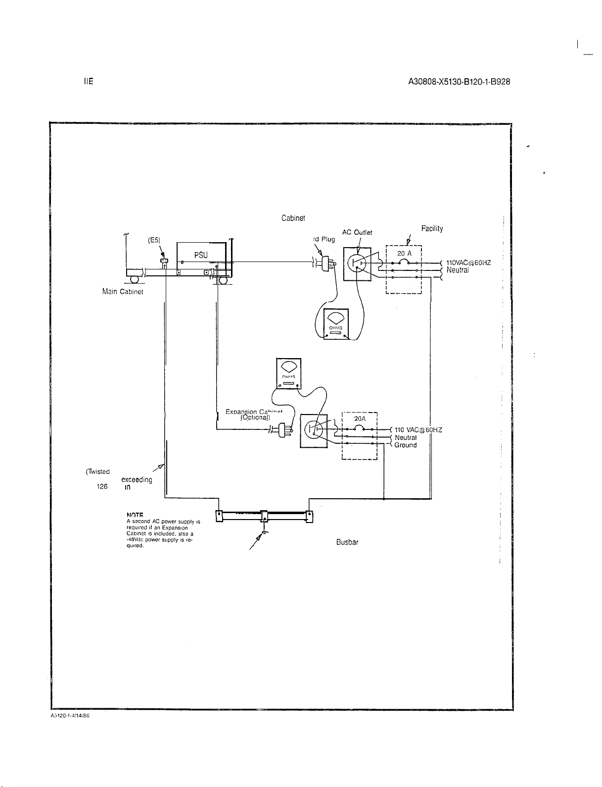
GND
LUG
(ES)
,
5,
hlatn Cabmel
(Rear View)
Recommended: B-gauge
(iwtsted
conductor not
Copper Wire)
exceedmg
i26
feet m length.
B D
BASIC Cabinet
Power co
PSU
El
El
I
(Ootlonall
f
Fuse Box Facility
llOVAC~$GOi-fZ
Neulral
Ground
3-2
I.1
f
Earth Ground Note: Single Point Ground (SPG) configuration IS shown
Master Ground
Busbar
Figure 3.00 System Ground Test Connections
Page 14
SATURN
Installation Test Procedures
IIE
EPABX
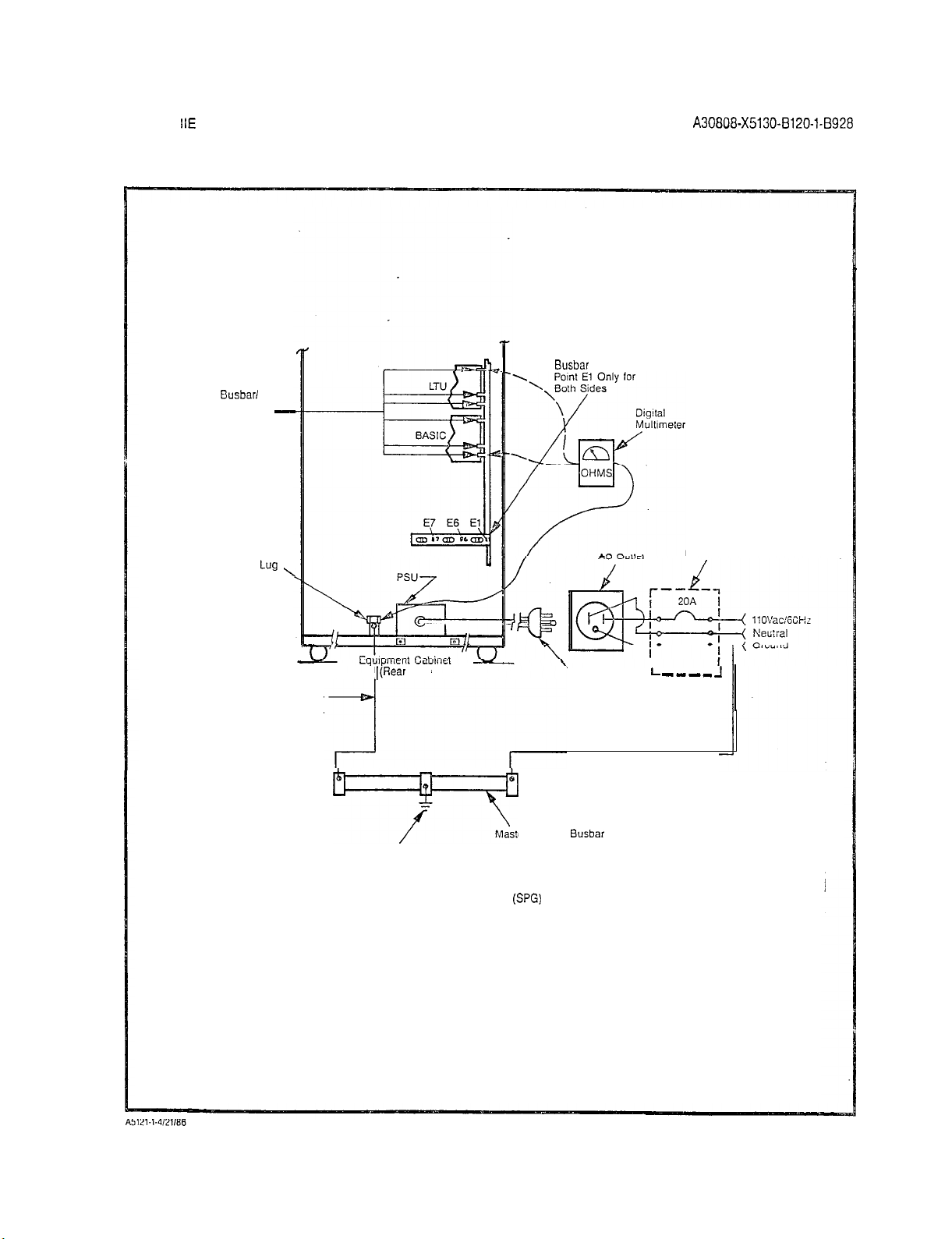
Busbar/
Backplane
Attaching
Screws
-
Busbar
A30808-X5130-8120-1-8928
Issue 1, May 1986
Grounded at
GND
Lug
No. E5
’
7
-
Recommended: 6 Guage
(twisted copper wire) conductor
not exceeding 126 feet in length.
7
I(Rear
View)
Master Ground
Earth Ground
Note: Single Point Ground (SPG) configuration is shown
\
Power
Cord Plug
Busbar
Fuse Box Facility
I
L
---_
-I
Figure 3.01 Shelf Ground Continuity Test Connections
3-3 (3-4 blank)
Page 15
I
-_
SATURN
installation Test Procedures
IIE
EPABX
SECTION 4.00 POWER-UP TESTS
4.01
tributed power in the equipment cabinet. Several power supplies are used in the system. These power supplies provide
voltage and message waiting voltage, from a
input power source. After satisfactorily performing the ground
tests
formed to ensure that proper power cable connections have
been accomplished and that the power supplies inside the
cabinet assembly have not been damaged during shipment.
General. The SATURN
+5Vdc, -SVdc, +12Vdc, -12Vdc, -48Vdc, 90Vac-20Hz
indicaied
YiEP
in Section 3.00, the following
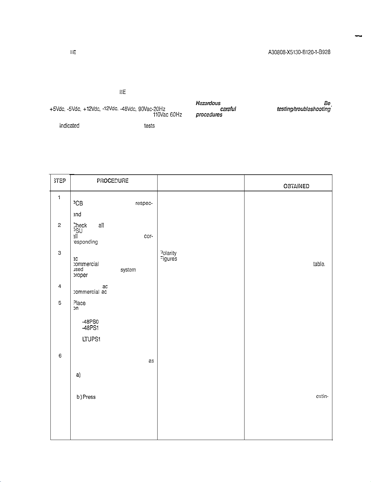
PROCEDtJRE
f not previously done, extract each
‘CB
in the system from its
ive backplane connector in basic
md
LTU shelves.
Check
that
‘SU
311
fuses are inserted in their
,esponding
all
are in the off positions and that
locations.
IIE
System makes use of dis-
tests
Table 4.60 Power-Up/Output Voltage Test
respec-
circuit breakers on the
cor-
ringing
11OVac 60Hz
must be per-
A30808-X5130-BlZO-l-8928
WARNING
Hazardous
extremely
pmcedures
4.02
the test procedures indicated in Table 4.00, check that all pow-
er cable assemblies are properly secured into their corresponding locations. Note that the test procedures in Table 4.00 include
procedures for testing the optional MSM, when equipped in the
system.
VERIFICATION
voltages exist within the equipment cabinet.
careful
when performing
with the equipment panel(s) removed.
Power-Up/Output Voltage Tests. Before proceeding with
IF VERIFICATION
IS NOT
Issue 1, May 1986
Be
testin@roubkshootjng’
08TAlNED
Jsing the digital multimeter (or an
3c
polarity indicator), verify that the
:ommercial
Jsed
Iroper
Connect the
zommercial
?lace
on
the PSU to the on (up) position:
a) Basic PS
b)
c)
d) LTUPSO (if equipped)
e)
ac power receptacle
for powering the
polarity.
ac
the following circuit breakers
-48PSO
-48PSl
(if equipped)
LTUPSl
(if equipped)
systsm
has the
ac
power cord(s) to the
power receptacle(s).
9 LTUPS2 (if equipped)
If the optional MSM module is
equipped in the system, proceed
follows:
2)
If not previously done, connect
and insert battery pack into
the MSM assembly.
b)Press
the BATTERY TEST
switch on the PSU and
release after verification has
been obtained.
2s
‘olarity
indication must coincide with
=igures
3.00 and 3.01.
The associated green LED should
light steadily.
if polarity indication does not coincide, correct before proceeding with
the remainder of test in this
If the green LED remains
guished, the battery pack is below
acceptable voltage limits. Let MSM
charge battery pack and retry test after 30 minutes have elapsed. If green
LED remains extinguished, the battery pack is defective and requires
replacement.
lable.
cxtin-
‘l-1
Page 16
SATURN
Installation Test Procedures
IlE
EPABX
A30808-X5130-8120-1-8928
issue 1, May 1986
SE?
8A
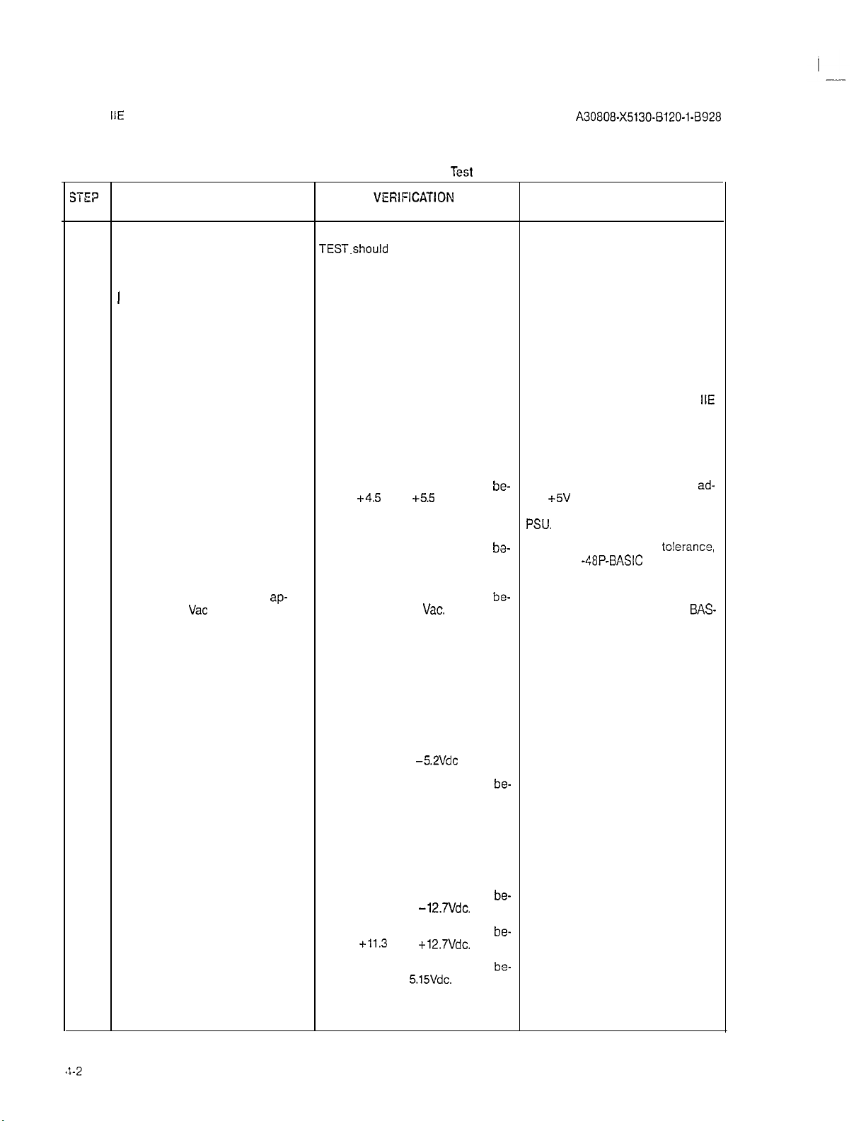
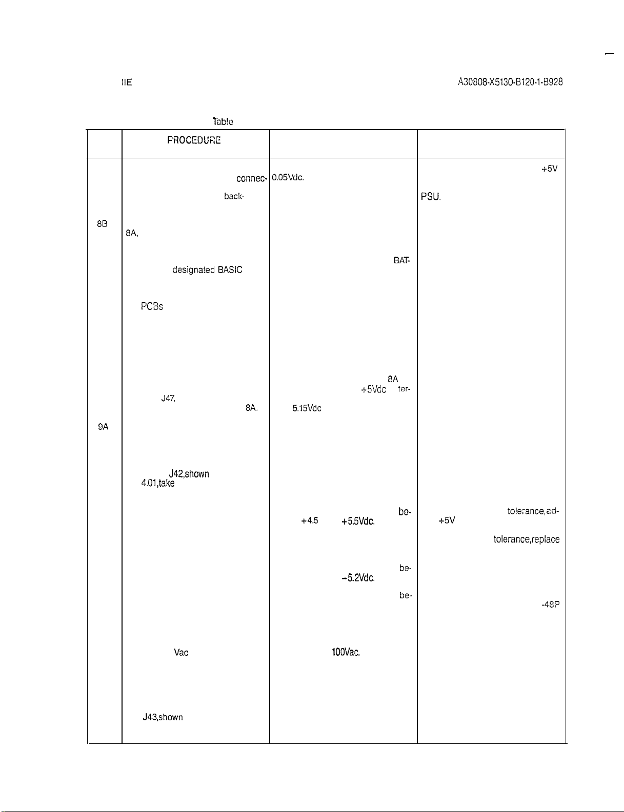
Table 4.00 Power-Up/Output Voltage
PROCEDURE
c) On the PSU, place the circuit
breaker designated BASIC PS
in the off (down) position.
d) On the PSU, place the circuit If the red LED remains steadily lit,
1
breaker designated BASIC PS be extinguished. either the cabinet ac power cord is
to the on (up) position.
7
Set digital multimeter to appropriate
dc voltage scale for the following If further troubleshooting information
tests.
To measure the unloaded basic shelf
input voltages, proceed as follows:
a) On basic backplane shown in
Figure 4.00, take reading be- tween
tween terminal El, E2, E3 or PSU. If still out-of-tolerance replace
E4 and ground.
b) On basic backplane connector
J46, shown in Figure 4.00, take
readings beiween pins 2 and 3. If fuse is good, replace -48PSO.
c) Set digital multimeter to
propriate
reading between pins 1 and 2 IC fuse on PSU. If fuses are good,
of J46.
d) Set digital multimeter to appropri-
ate Vdc scale and take readings
between the following pins on
basic backplane connector J47
(shown in Figure 4.00):
1) Pins 1 and 3.
2) Pins 2 and 3.
e) On basic backplane connector
J48, shown in Figure 4.00, take
readings between the following
pins:
1) Pins 1 and 4.
2) Pin 2 or 3 and pin 4.
3) Pins 4 and 5.
Vat
scale and take
ap-
The red LED designated BATTERY If the red LED remains extinguished,
TEST.should
The red BATTERY TEST LED should
Voltage measured should read
Voltage measured should read
tween -43 and -53Vdc.
Voltage measured should be
tween 75 and 100
Voltage measured should be between -4.9 and
Voltage measured should be
tween -43 and -53Vdc check the -488 BASIC fuse on PSU.
Voltage measured should read
tween -11.3 and
Voltage measured should be
tween
Voltage measured should be
tween 4.85 and
VEfiIFICATION
be steadily lit. replace the MSM.
+4.5
and
+11.3
and
Test
(Continued)
+5.5
Vdc. just
Vat.
-5.2Vdc
-12.7Vdc.
+12.7Vdc.
5.15Vdc.
IF VERIFICATION
IS NOT OBTAINED
not connected to the commercial ac
power receptacle or a local ac power failure has occurred.
NOTE
is required during these testing
procedures, refer to SATURN
EPABX Maintenance and
Troubleshooting Practice.
be-
If reading is not within tolerance,
+5V
ADJUST potentiometer on
PSU.
bo-
If reading is not within
check the
be-
If the voltage is not present, check
and replace RGEN fuse or RAC
replace RGEN PCB. If voltage still not
present, replace PSU.
If reading is not within tolerance,
replace the PSU.
be-
If reading is not within tolerance,
If the fuse is good, replace -48PS0.
be-
If reading is not within tolerance,
replace the PSU.
If reading is not within tolerance,
be-
replace the PSU.
be-
If reading is not within tolerance,
check that J16 on the rear panel of
the PSU is strapped to the MSM terminal. If the strap is in place, replace
the MSM.
-48P-BASIC
IIE
ad-
to!erance,
fuse in PSU.
BAS-
Page 17
I
-
SATURN
Installation Test Procedures
STEP
813
IIE
EPABX
FROCEDUEE
f) Connect positive lead of digital Voltage measured should read + If reading is not 0.05 Vdc, adjust
multimeter to pin 5 of
tor J48 and negative lead to
terminal El on basic
plane. (Refer to Figure 4.00.)
After satisfactorily completing step
8A,
proceed as follows to measure
the loaded basic shelf input voltages.
a) On the PSU, place the circuit The MSM red LED designated
breaker
in the off (down) position.
b) Plug all previously extracted
PCBs
their respective backplane
connectors.
c) On the PSU, place the circuit
breaker designated BASIC PS TERY TEST should be extinguished.
in the on (up) position.
designa?ed BASIC
on the basic shelf into
lbb!c
4.00 Power-Up/Output Voltage Test (Continued)
VERIFICATION IF VERIFICATION
connec- 0.05Vdc.
back-
PS TERY TEST should be steadily lit.
The MSM red LED designated BAT-
A3G808-X5130-B120-1-B928
Issue 1, May 1986
IS NOT OBTAINED
ADJUST potentiometer on PSU. If
adjustment is not effective, replace
PSU.
BAT-
.
+5V
d) Repeat measuring procedures Same verification as in steps 8A a)
on basic backplane connectors
J46,
J47,
El-E4 as indicated in step
9A
To measure the unloaded LTU shelf
input voltages (if applicable), proceed
as follows:
a) On the LTU backplane con-
nector
4.01,take
the following pins:
1) Pins 1 and 3.
2) Pins 3 and 5.
3) Pins 3 and 4.
4) Set digital multimeter to
b) Set digital multimeter to ap-
propriate Vdc scale.
J48 and terminals
J42,shown
a reading between
read
Vat
tween pins 2 and 3.
in Figure
and connect be-
8A.
through e), except that
minal El should read between 4.85
and
5.15Vdc
under load.
Voltage measured should be
tween
+4.5
and
Voltages measured should be
tween -4.9 and
Voltage measured should be
tween -43 and -53Vdc.
Voltage measured should be be- If voltage is not present,
tween 75 and
+5.5Vdc.
-5.2Vdc.
1OOVac.
-t-S!/&
at
ter-
be-
If reading is not within
just
+5V
LTUPS. If the adjustment does not
bring voltage into
LTUPS.
be-
replace appropriate LTUPS.
be-
verification reading, check the
check/replace RGEN fuse or RAC
ADJUST potentiometer on
tolerance,replace
If reading is not within tolerance,
If reading does not coincide with
LTU fuse on PSU. If fuse is good,
replace -48PS0.
LTUO fuse on PSU. If fuses are good,
replace PSU.
to!e:ance, ad-
-48P
C) On LTU backplane connector
J43,shown
a reading between the following pins:
in Figure 4.01, take
4-3
Page 18

SATURN
IIE
EPABX
Installation Test Procedures
A30808-X5130-B120-l-6928
Issue 1, May 1986
STEP
98
Table 4.00
PROCEDURE
Power-Up/Output
VEFllFlCATlON
Voliagc?
Test (Continued)
IF VERIFICATION
IS NOT OBTAINED
1) Pins 1 and 3. Voltage measured should read
tween
+4.5
and
+5.5Vdc.
be-
If reading is not within tolerance,
just
+5V
ADJUST potentiometer on
LTUPSO. If adjustment does not bring
the voltage into tolerance, replace
LTUPSO.
2) Pins 1 and 2. Voltage measured should read
tween -43 and -53Vdc.
be-
If reading is not within tolerance,
replace -48PS0. If voltage not
present, check
-488
PSU. If fuse is good, replace 48PS0.
3) Pins 1 and 4.
Voltage measured should read
tween
+11.3
and
+12,7Vdc.
4) Pins 1 and 5. Voltage measured should read
-. ttieen
-11.3 and
-12.7Vdc.
d) On LTU backplane connector Voltage measured should read
J44 shown in Figure 4.01, take tween
+4.5
and
+55Vdc.
If reading is not within tolerance,
be-
replace LTUPSO.
be-
If reading is not within tolerance,
replace LTUPSO.
be-
If reading is not within tolerance,
check
+5V
cabling between
a reading between pins 1 and tween basic shelf and LTU
2 or pins 1 and 3.
Repeat steps 9A a) through d) for expansion cabinet LTU shelf voltages
(if applicable) substituting
-48PSl
for
48Vdc power supply and appropriate
LTUPS.
ad-
LTUO fuse on
be-
9C
After satisfactorily completing steps
9A
and
96,
proceed
measure the loaded LTU shelf input
voltages:
a) On the PSU, place the circuit
breakers designated
LTUPSO,LTUPSl,and
in the off (down) positions.
b) Plug all previously extracted
PCBs
on the LTU shelves into
their respective backplane
connectors.
c) On the PSU, place the circuit
breakers designated LTUPSO,
LTUPSl,
and LTUPS2 in the
on (up) positions.
d) Repeat measurements on LTU
backplane connectors J42, same tolerances except
J43, and J44 per step
2s
follows to
LTUPS2
9A.
Voltages measured should be within
+5Vdc sup-
ply should read between 4.85 and
5.15 Vdc.
4-4
Page 19

I
SATURN
lnstallatlon
IIE
EPABX
Test
Proccdurcs
A30808-X5130-8120-1-8928
Issue I, May 1986
J46/P46
J47/P47
Figure 4.00
Location of Input Voltage Connectors
011
Basic
Bockplnnc
Page 20

i
---I
SATURN
nstallation
IIE EPABX
Test Procedures
A30808-X5130-8120-1-8928
I
Issue 1, May 1986
:42/?42
J43/P43
J44lP44
Figure 4.0.1
Location cf Input
Voltage
Connectors on LTU
Dackp!ane
Page 21

SATURN
Installation Test Procedures
5.01
Controlled (SPC) system. The system is shipped with two identical floppy disks that contain the basic operating and the
installation-dependent data. The operating program uses the
installation-dependent data, commonly referred to as the system data base, to complete and process calls as required by
the customer. This information includes such items as the
number of station lines and trunks in the system, as well as
their operating characteristics.
The exact equipment configuration of the SATURN
tem must be defined in the data base in order for the system
to operate properly. Depending on how the system is ordered,
the data base is supplied in a standard format or, on request,
can be supplied completely defined and prepared by Siemens.
When the standard data base format is supplied, via the
SATURN EPABX Data Base Preparation practice, the equip-
ment configuration of the particular installation-site must be
evaluated to determine if additional information must be ad-
ded to the floppy disks. The floppy disks are updated via a
service terminal. The procedures for defining the data base
and inputting the data to memory are described in the
SATURN EPABX Data Base Preparation practice and
SATURN EPABX Customer Memory Update (CMU) Proce-
dures practice.
5.02
ing the Power-Up/Output Voltage Tests in Section 4.00, the
IIE
EPABX
General. The SATURN
boadjng
Operating
D&a.
IIE
EPABX is a
After
Stored-Program-
satisfactoriiy
IIE
Sys-
complet-
system’s operating program, contained on the floppy
is loaded into the FDD modules for the initial processor initialization. Both floppy disks are loaded, with either disk
placed in either drive (FDDO or
the loading procedures indicated in Table 5.00, the following
precautions must be observed when handling the floppy disks.
Figure 5.00 illustrates the floppy disk and storage envelope.
a.
Prior to using a floppy disk, leave disk in the same en-
vironment as the FDD module for at least 5 minutes.
b. Do not place heavy objects on floppy disk.
c. Do not write on floppy disk.
d. Do not touch floppy disk suriace while
Damage to FDD head may occur due to skin oil pick-
ing up dirt.
e.
Always return floppy
is not in use.
5.03
Inputting CMU Data to
torily loading the operating disks as indicated in Table 5.00,
refer to the SATURN EPABX Data Base Preparation practice
which defines the particular system’s data base,
EPABX Customer Memory Update (CMU)
tice to input the installation-dependent
A30808-X5130-B120-l-8928
FDDI).
dislc
to storage envelope when it
F!oppy
Issue 1, May 1986
Before proceeding
Disk. After satisfac-
and
Prccsdures
da?a
to memory
Uisks,
with
hand!ing.
SATURN
prac-
Centering
Hole
Read/W
Window
Protective
Envelope
Storage
Envelope
1
Index
Hole
I
I
Figure 5.00 Floppy Disk and Storage Envelope
Page 22

SATURN IIE EPABX A3080&X5130-B120-l-8928
Installation Test Procedures Issue 1, May 1986
WARNING
;TEP
1
2
3
4
Hazardous voltages exist within the equipment cabinet. Be
performing
testir;g/~roobleshooting procedur-
LJ with the equ&ment
e&e&y
Table 5.00 Loading Procedures for Operaling Disk
PROCEDURE
VERIFICATION
On the PSU, shown in Figure 5.01,
place the
FAtLURE
TRANSFER
switch in the AUTO position,
Insert a floppy disk into slot opening
of each FDD until it stops (Figure 5.02).
NOTE:
Either system disk may be placed in
either FDD.
Close FDD latch to secure floppy disk
in place.
Perform the following operations on
the CIOP PCB (Figure 5.03).
a) Connect service terminal to
Set CIOP DlP switches (Figure 5.03)
TTY connector on CIOP PCB for service terminal in use per Table
(Figure 5.03).
b) Depress the reset switch locat-
ed under the
CIOP llY con- appear on the service terminal: the LEDs flash a binary value to indi-
5.01.
The following ihree messages should
nectar. Use pencil or other
nonmetallic object to depress
the switch.
1) THE SIB SIDE IS READY FOR
USE
2) READY TO START BOOT
LOADER initialization, remove the floppy disks
BOOT LOADER COMPLETE”’
3)“*
After the last message, the red
STO-ST3 LEDs perform a cycling
sequence and the green ACTV LED re-
mains lit.
When the loading process is com-
plete, the red LEDs stop cycling and
one LED remains lit for a few seconds, then cycling starts again. The
green LED (ACTV) remains lit.
If no failures occur during processor
initialization, the four red
LEDs
display
a code indicating that processor initialization has been completed and
the processor is on-line. Concurrently, the service terminal displays soft-
ware version, date base version, patch
level of disk software, site information
and the prompt ENTER PASSWORD.
If it is desired to perform CMU procedures or clear the alarm stack, enter
the appropriate password. If the
proper password is entered, a date-
and-time prompt is displayed. If an incorrect password is entered, INVALID
PASSWORD ENTERED is displayed.
careful when
panel(s) removed.
!F
VERIFICATION
IS NOT
OBTA!NED
If a failure occurs during initia!ization,
cate loading error as described in
Ta-
ble 5.02.
Should any of the failures described
in Table 5.02 occur during processor
from FDDs and insert the spare flop-
py disks into the FDDs. If no failures
cccur, the floppy disks previously re-
moved are defective. If the same
failure occurs, refer to ACTION
cOlumn in Table 5,02
5-2
Page 23

SATURN
Installation Test Procedures
IIE
EPABX
A30808-X5130-0120-1-8928
lssuc
1, May 1936
Table 5.00 Loading Procedures for Operating Disk
STEP
5
If the operating disks that were loaded did not contain a Siemens-.
prepared data base, refer to SATURN
EPABX Data Base Preparation practice to define the particular system
data base, and the SATURN EPABX
Customer Memory Update Procedures practice to input the
dependent data to the system
memory.
SWITCH
NUMBER SWITCH ON (CLOSED) SWITCH OFF
1
2
PROCEDURE
installation-
Table 5.01
Before
removing
to the off
to
the
on (up) position.
Maintenance/ Test Normal
Not Used
GOP
(c?own)
PCB to set switches, place BASIC PS circuit
position. After replacement of
VERlFlCATlON
CIOP
DIP Switch Settings
CAUTION:
ClOP
PCB, place circuit breaker
Not Used
(Continued)
brea!:er
IF
IS NOT OBTAINED
on
VERIFlCAT!ON
’
lhe PSU
back
(OPZX)
3&4
5
6
7
8
NOTE: The following are the baud rate combinations for switches 3 and 4.
Baud Rate (see note) Baud Rate (see
One Stop Bit Two Stop Bits
Odd Parity Even Parity
Parity Disabled Parity Enabled
Seven Bits Eight Bits
SW3
OFF OFF
ON OFF
OFF
ON ON
SW4
ON
BAUD RATE
300
1200
2400
9600
no?e)
5-3
Page 24

I’
Table 5.02
ST0
LED
OFF
:z
OFF
OFF
OFF
OFF
OFF
ON
ON
ON
ON
ON
ON
ON
ON
Notes:
1.
2.
3.
ST1
LED
I
OFF
OFF
OFF
OFF
ON
ON
%
ON
ON
ON
%F
OFF
OFF
OFF
Upon failure, retry loading procedure. If failure persists, replace
Upon failure, retry loading procedure using another set of floppy disks. If failure persists,
and then
If reload and
is no longer present.
ST2
LED
OFF
OFF
ON
ON
OFF
OFF
%
OFF
OFF
ON
%F
OFF
ON
ON
CIOP
CIOP
ST3
LED
OFF
ON
OFF
ON
OFF
ON
OFF
ON
OFF
ON
OFF
ON
OFF
ON
OFF
ON
PCB, if necessary.
PCB replacement (Noie 1) is not effective, replace memory
HEX
CCDE
0
2
3
4
5
:
LED Display Values for Loading Errors
ERRCR
DETECTED
Start of self test not halted
1
6
D
E
F
8
9
A
I3
Main processor error
EPROM checksum
MEM slot 0 low 64k test error
8k by 8 static RAM test error
IRAM
memory test error
ORAM
memory test error
SIB side error
Global memory
Watchdog iimer error
SIB serial
SIB counter timing test error
Start boot process (self test done)
Disk
Drive not ready error
CRC retry
loopback
coniroller
errcrs
error
error
test error
error
exceed 8
CIOP
PC3.
PCBs
starting from
A30808-X5130-(3120-l-8928
chcc!i/replace
Issue 1,
sloi
May
ACTION
_._________-________
Note 1
Note 1
Notes 1 and 3
Noie 1
Note 1
Note 1
Note 1
NOieS
1 and 3
Note 1
Note 1
Note 1
______-___--___-____--
Note ‘1
Note 2
Note 2
disk drives
0 until failure
1986
Figure 5.01
Po*wr Sys?em
Unit (Front
View)
Page 25

I
--
SATURN
Installation Test Procedures
IIE
EPABX
LATCH
OPEN\
LATCH
CLoSED
\
/
/
?
0
A30808-X5130-6120-1-8928
/
Issue 1, May 1986
WRITE
PROTECT
NOTCH
FLOPPY
DiSi’c
25
Figure 5.02
Floppy Dish Loading
Proceduics
Page 26

I
-
SATURN
Installation Test Procedures
IIE
EPABX
LED
LED
(Red)
A30800-X5130-6120-l-8928
Issue 1, May 1986
ST3
LED
ACTW
LED
Connector
Service
Terminal
r
‘witch
5-6 (6 pages)
Figure
5.03
CIOP
Printed
Circuit Coard
Page 27

SATURN
Installation Test Procedures
6.01
and inputting CMU data to system memory via a service terminal, the operational capability of the system must be verified after the necessary MDF cross-connections are
performed. The SATURN
group of system and apparatus (ancillary equipment) diag-
nostic test routines which are accessed via the maintenance
phone. Resulting visual and/or audible responses from these
on-line diagnostic tests make it possible to verify correct operation or detect and isolate system and apparatus malfunctions. If in doubt about a SATURN PCB or apparatus
maliunctioning,
IIE
ther details. If a SATURN PCB or apparatus is proven to be
IIE
EPABX
General. After satisfactorily loading
IIE
System software contains a
EPABX Mainionance and Troubleshooting
craft personnel should refer to the SATURN
the cperating
praciice
disk
for fur-
defective, craft personnel should proceed according to the
instructions contained in the MRA kit.
6.02
Connecticn
Figures 6.00 and 6.01 provide the details for the maintenance
phone and modem initial MDF cross-connections. Figure 6.00
also identifies the leads used when interfacing other maintenance related equipment such as a power failure transfer
subsystem and dry contact closures for remote minor and
major alarm indications. Note that such equipment is
customer-provided and craft personnel should follow the
manufacturer’s instructions when installing them. To connect
ihe
maintenance phone and modem, the initial MDF
connections
a.
Maintenance Phone. At the MDF connecting block on
which PSU cable J13 is terminated, cross-connect the
T&R leads of pair number 1
leads of the subscriber line circuit assigned for main-
tenance purposes (refer to Figure 6.00 for details). Note
that this subscriber line circuit must be classmarked
with the Maintenance Diagnostic Test
Apparatus Test (TSTAPP) features.
b.
Modem. From the system T&R connecting block that
allocates system MDF cable J44 from the basic shelf,
cross-connect the T&R of pair number 24
to the T&R leads of the subscriber line circuit to be used
for modem application (refer to Figure 6.01 for details).
The subscriber line circuit to be used for modem application must be assigned to a class of service in
which the Data Line Security (DATASEC) classmark has
been enabled.
After the above initial MDF cross-connections have been
performed, the DTMF telephone set to be used as the
maintenance phone can be connected to the modular
jack designated MTCE PHONE on the PSU if equipped
with a standard modular plug, or connected at the MDF
to the T&R leads of the associated subscriber line circuit. Note that if a permanent maintenance phone is
of Maintenance
aie
as follows:
Phcne
and Modem.
(W/BL- BL/W)
(TESTDIAG)
cross-
to the T&R
and
(V/BR- BR/V)
A30808-X5130-BlZO-l-8920
desrred
in tho equipment, it may be installed
front of the cabinet, and cross-connected per Figure 6.02.
6.03
MDF
tenance
ed, perform the necessary MDF cross-connections according
to the equipment configuration plan. The following
tions are provided to assist craft personnel in the MDF cross
connections of peripheral interfacing devices:
Cross-Connecting Procedures. After the main-
phone and modem connections have been complet-
a.
Figures 6.02 and 6.03 - Cross-Connections for rotary
or pushbutton Single Line Telephone Instruments interfacing with SLMA-S and
b.
Figure 6.04 - Cross-Connections for Siemens Digital
Telephone Interfacing with SLMD PCB.
C.
Figure 6.05 - Cross-Connections for SATURN
dant Console.
d.
Figure 6.06 - Cross-Connections for Central Office
(CO) and Direct Inward Dialing (DID) Trunks.
e.
Figure 6.07 - Cross-Connections for Two-Wire (Type
E&M Tie Trunks.
f.
Figure 6.03 - Cross-Connections for
I)
E&M Tie Trunks.
Figure 6.09 - Cross-Ccnnections for
9.
E&M Tie Trunks.
h.
Figure 6.10 - Cross-Connections for Four Wire (Type
II) E&M Tie Trunks.
i.
Figure 6.11 - Cross-Connections for Recorded Announcement Equipment (DID and Tie Trunk Vacant
Number Intercept, and ACD Announcement Service).
Figure 6.12 - Cross-Connections for Coda Calling
i
Equipment with or without
k.
Figure 6.13 -Cross-Connections for DTMF Dial Dictation Equipment.
I.
Figures 6.14 and 6.15 - Cross-Connections for
on-Hold Feature via a Music Source, interfacing with
a TMBA4 and an
m
Figure 6.16 - Cross-Connections for Zoned Paging
Equipment With Answerback Capability.
n.
Figure 6.17 - Cross-Connections for Zoned Paging
Equipment Without Answerback Capability.
0.
Figure 6.18 - Cross-Connections for Zoned Universal
Night Answer (ZUNA or UNA) Signaling Equipment,
SLMA/SLAlG
Issue 1. May 1986
SLA16 PCBs,
Four-l”dirc (T]pe
T;:jo-Wire (T]pe I!)
Answerbaclc
PCB, respectively.
neartho
’
illusira-
respectively.
Atien-
I)
Capability.
Music-
6-l
Page 28

I
.-
SATURN
lnstallatlon
IIE
EPABX
Test Procedures Issue 1, May 1986
,-Syslein
MDF
Cable
Cross-connect
for the maintenance telephone.
PXFER
1
J
PXFER (Normally Closed)
J13
.to
SLMA circuit designated
(No&h Ooen1
,
\$$!
14
0
D > FUBL
I
Cross-connect to failure transfer
relay(s) subsystem (customerprovided).
>
:tG
TIP(Major-NC)
>
RING (Major Common)
TIP (Major-NO)
A30808-X5130-B120-l-B928
Dry contact closures
for remoie
major alarm indications (customerprovided).
miner
and
Syslem Maiafcnancc
Figure 6.00
Note: The cross-connections shown are used for the
Mainienance
RAUP PCB.
Phone and Mainienance-Related Cross-Conneciions
System MDF Cable 144 from Basic Shelf
Connecting
rSystem
Blsck
T&R Connecting Block
Cross-connect to SLMA circuit i
designated for Modem application. !
Figure
G.01
Modem Cross-Connections
Page 29

SATURN
Installation Test Procedures
IIE EPABX
A30808-X5130-B120-1-6928
Issue 1, May 1986
SlNGLE
TELEPHONE
Note: Dashed
I
I
LINE ’ HOUSE
!
CABLING I
lilies
represent installation-dependent cross-connections.
Figure 6.02
I
/
I
I
Inlerfacing
----------
-+(-Jo--- -________
Sing!e
Line Telephone Cross-Connections Using
EQUIPMENT ROOM
Connecting Block
f
[
---I
System
T&R
Connecting Block
Sys:em MDF Cable J32, J34. J36. C38.
or J44 from
J32. J34. J36. J38, or J40
the EZISIC
I
SLMA
shelf or
PC5
J26, J28, J30,
from tile
JSO,
J42
LTU shelf
I
SINGLE LINE
TELEPHONE
I
HOUSE
i
CABLING
I
Interfacing Connecting Block
\I
EWIPMENT
r
\ \ \
Notes: Dashed lines represent installation-dependent cross-connections
Figure 6.03 Single Line Telephone Cross-Connections Using
ROOM
System T&R
yecling
Block
System MDF Cable J321J33, J34/J35, J3EN37,
J381J39, J401J41, J42/J43.
Basic
shelf; or
J32/J33, J34/J35, J36/J37, J38/J39
\ from
Lhe
LTU shelf.
SLA16
or
J26N27, J28N29, J3O/J31,
J441J45
or
PCB
from
J4O/J41
the
6-3
Page 30

SATURN
Installation Test Procedures
IIE
EPABX
A30808-X5130-B120-l-8928
Issue 1, May 1986
I
SIEMENS
DIGITAL : HOUSE
TELEPHONE
DYAD
or
Jr-DYAD
Note: Dashed lines represent installation-dependent cross-connections
ICABLING!
I
I
I
1
Figure 6.04 Siemens Digital
I
I
’
.
I
I
Interfacing
I\
.
EQUlPMENT FiOOM
Connecting Block
Te!cphone
System T&R Connecting Block
System MDF Cable J32, J34, J36. J38, J40. J42 :
or J44 from the Basic shelf or
J32, J34, J36, J38, or
Cross-Connections Using
SLMD PC9
J26,
J40
J28,
from the LTU shelf
1
J30,
j
6-4
SAbRN
ATTENDANT
CONSOLE
Note: Dashed lines represent installation-dependent cross-connections.
Figure 6.05 SATURN Attendant Console Cross-Connections
HOUSE
CABLING
i
I
Interfacing Connecting Block
EQUIPMENT ROOM
System T&R Connecting Block
System MDF Cable J32, J34. J36. J38. J40. J42
or J44 from the
J32, J34, J36, J38. or
Basic
I
shelf or
J25
J40
J28,
from the LTU shelf j
J30,
i
;
Page 31

SATURN
Installation Test Procedures
IIE
EPABX
A30808-X5130-B120-1-6928
Issue 1, May 1986
DISTANT
OFFICE
OR
SlGNALING
EQUIPMENT
CENTRAL
OFFICE
co QP C3D
Trunk
Circuit
NO!%
Dashed lines
;
TRUNK
I FAClLlTY :
I
I
I
represcnl ins!allalion-dependenr cross-CCnnEcfions
TRUNK
FACILITV
Figure
i
1
;
Local Telephone Company
Interfacing Connecting
i
G.06 63
and
Interfacing Connecting Block
CUSTOMER PREMISES
Bloc!c
System
MDF
or J44 from the Basic shelf or J26, J28. J30, J32,
J34. J36, J38. or
L
DID
Trunk Cross-Connections
CUSTOMER
Cable J32. J34,
System T&R Connecting
PREMlSES
System T&R Connecting Block
J35, J38, J40.
J40
from the LTU shelf
Dock
ystem MDF Cable J32.
44 from the
36.
J38,
or
Dasic
J40
shelf or
from
J42
J34. J36. J33. J40.
J26. J28. J30.
the LTU
shelf
J32,
J42 or
J34,
I
i
Figure 6.07
System E&M Connecting Block
Two-Wire (Type I) E&M Trunk Cross-Connections
J39, J41. J43, or
‘3.
J31, J33. 335.
if
6-5
Page 32

I
-
SATURN
Installation Test Procedures
IIE
EPABX
DISTANT
OFFICE
OR
SIGNALING ;
EQUIPMENT
I
-l-RUN!<
;
FACILITY 1
I
I
I
I
I
I
Interfacing
Connecilng
CUSTOMER PREMISES
Block
System T&R
Y
L
System
Connecting Bloc!c
System MDF Cable J32. J34.
or J44 from the Basic shelf or J26. J28, J30, J32,
J34, J36,
L
System
or J45 from the Basic sheif; or J27. J29, J31, J33,
J35. J37,
E&M
Connecting
J38,
or
J40
MDF
Cable J33, J35,
J39 or
J41
6lock
A30808-X5130.B120-l-8928
from the LTU shelf
from the LTU
Issue 1, May 1986
J36, J38. J40,
J37,
J39,
J41,
she!f
J42
J43,
A5135-1-4/W3!3
DISTANT
OFFICE
OFI
SIGNALING
EQUIPIMENT
Figure
I
TRUNK
t
FACILITY
(
I
I
6.06
Four-Wire (Type ;)
f
:
I
i
t
i
Interfacing Connecting Block
I
a
E&M
Trunk Cross-Connections
CUSTOMER PREMISES
L-.
~System
System
T&R Connecting
Lo
System MDF Cable J33, J35,
or J45 from the
J35, J37, J39 or J41 from the
E&M.
Connecting
B!ock
System MDF Cable J32, J34.
or J44 from the Basic shelf: or J26. J28. J30, J32,
J34, J36. J38, or
Elock
J40
from the LTU shelf
Baw
shelf; or
J36, J38, J40,
J37.
J39. J41, J43,
J29, J31, J33,
J27,
LTU
shelf
J42
I
6-6
Figure 6.09 Two-Wire (Type II) E&M Trunk Cross-Connections
Page 33

I
--
SATURN
IIE
EPABX
A3080i3-X5130-B120-1-69.28
Installation Test Procedures Issue 1, May 1986
DISTANT
OFFICE
OR SIGNALING
EQUIPMENT
TRUNK
FACiLlTY f
;
CUSTOMER
In:er:ach~g Conneclmg
PfiErvwzs
Block
System T&R
Connecilng
Block
634. J3S. J30. J40.
J28.J~O.J32,~34.J3S.J33.
J42 or
I
J44‘
r------
I
Type II
I
Four-Wire
Trunk
or
Signaling
Circuit
E&M
R
-
I!
Rl
E
-
SC
-
M
-
SE
-
System E&M Connecting Block
35,
7.
J29,
J37,
J31.
J39. J41.
J33,,‘35, J37, J29
JS3.
or
J45
E!o!e:
Dashed lines represent in
Typical
Announcement
Equipment
G
Audio
output
8
1
SMl @
SM2 @-
SZl a-
sz2 a-
Some ann~uncemenl
Busy (MB)
signals
s:al!ation-dependent crcc;-connections.
Figure 6.10 Four-Wiro (Type
-------
-------
___-----
------
machines send both Start Message (SM) and
over same
par
(EAIEB).
ii) E&M Tiunlc Cross-ConnecZions
or J44
J34.
J36. J38.
Make
u
P
-
System MDF Cable J33. J35, J37, J39, J4!, J43,
or J45 from the Basic shelf; or J27, J29. J31. J33.
J35, J37, J39 or J41 from the LTU shelf
System E&M Connecting
Cable
J32.
J34,
from
the Basic shelf or J26. J28, J30, J32,
or
J40
from the LTU shelf
Block
J36. J33. J40, J42
A5126-l-4,8/86
Figure 6.11 Recorded Announcement (DID and Tie Trunk Vacant Number intercept, and
AC3
Announcement Service) Cross-Connections
6-7
Page 34

SATURN
Installation Test Procedures
IIE
EPABX
Connecting Block
A30808-X5130-B120-l-8928
System T&R Connecting Block
Issue
1, May 198G
No:es:
~Il”-i-4:oIES
Dashed lines represent installation-dependent
Ei-drrecticnal
swerback
Maximum of one code calling equipment (with or without
bility)
When maintenance procedures are to be performed on code
ment, associated trunk circuit must first be taken out-of-service. Failure
to observe this will cause users accessing code calling to receive unanswered
connection to code calling device for both calling and
channels shown.
can be interfaced with the system.
ringback
tone instead of busy tone.
Code
Figure 6.12
Cailing
cross-connectrons
answerbaclc capa-
callrng
(With or Without
equip-
Answcrba~h) Cross-Comedons
an-
stem
,
J42 or J44 from the Basic shelf or
, J28,
m the LTU shelf
System MDF Cable J32, J34,
J36, J38, J4.0, J42 or J44 from the
Basic shelf or
J25,
J28,
J30,
J32,
J34, J36, J38, or J40 from the LTU
sheif
MDF Cable J32, J34,
J30,
J32, J34, J36, J38, or
J36, J38,
J40
Notes: Dashed lines represent installation-dependent cross-connections,
Bi-directional connecction
Maximum of four DTMF dial dictation circuits can be interfaced with the
system.
When maintenance procedures are to be performed to a dial dictation equip-
ment, the associated SLMA crrcuit must first be taken out-of-servrce. Fatlure
to observe this
hunt
to
instead of being routed to an in-service device or receiving busy tone.
will
an out-of-service device and receive unanswered
to DTMF dictation equipment shown.
cause users accessing the dial dictation equipment to
Figure 6.13 Dial
Dic?ation
ringback
(DTMF) Cross-Connections
tone
Page 35

SATURN
Installation Test Procedures
IIE
EPABX
A30808-X5130-B120-l-8928
Issue 1, May 1988
Interfacing
Connectmg
(Op!lonal)
System E&M Connecting Block
Notes: Dashed lines represent installation-dependent cross-
connections. Broadcast type connection from music source
shown. Two kinds of music source can be cross-connected, con-
tinuous type and demand type. For
leads are not used; and for demand music, the E&M leads are
Figure 6.14
Music-cn-Wc!d
Block
continuous mustc,
System
A----
h
the E&M
Cross-Connections Using
T&R Connecttng 61ocl(
System MDF Cable
from the Basic shelf or J26. J28, J33, J32, J34, J3G. J38.
or
J40
from the LTU shelf
L
System MDF Cable J33: J35, J37, J33. J41, J43. or J45
from the @asic shelf; or J27, J29, J31, J33, J35, J37, J39
or J41 from the LTU shelf
J32. J34. J36.
.Jm.
J40.
J42
TMBA4 PC0
or
J44
I
r
j
I
EQUIPMENT ROOM
Interfacing Connecting
Sloc!c
T
System
T&R
System
or J44 from the Basic shelf or J26,
J34, J36,
Music Source
- - - - -
Notes: Dashed lines represent installation-dependent cross-
connecttons.
System MDF Cable connections are shown for an
SLMA
PCB.
For
SLA16
6.03.
Only continuous type music sources may be crossconnected.
connections, refer to
Figure 6.15 Music-on-Hold Cross-Connections Using
-----
T
-
Ftgure
Connecting Block
MDF
Cable J32, J34. J36,
J38, or
J40
from the LTU shelf
\a
,--\ T
I
1
SLMAiSLAl6
Station Line
Circuit
Within an
SLMAlSLAlG
PCB
J36, JSO,
J26, J30,
PCB
J42
J32,
6-9
Page 36

System
__----
-------
-----mm
--------
-------
E&M
Connecting
A30808-X5130-0120-1-8928
Block
System MDF Cable J3.2, J34. J36, J36. J40, J42
or J44 from the Basic shelf or J26,
J32, J34, J36.
J36,
or
Trunk Circuit
issue 1, May 1986
JSO
from the LTU shelf
J26, J30.
A5!59-,-4,9:66
Typical
Paging
Equipment
Audio
8-
Input
i
0
BSYl
0
BSY2
0
PGl
0
PG2
0
System E&M Connecting
Figure 6.16 Paging With Answerback Cross-Connections
---------
Interfacing
Connecting Block
(Optional)
[IO’
used’pJ
k/--j
.,,-I
r---m7
i
-w---1
L----
--1
I
I
7
L--w--
I
I
L---s--
Block\
System T&R connecting Block
L
System MDF Cable J33. J35. J37, J39, J41, J43,
or J45 from the Basic shelf; or J27, J29, J31,
J33, J35, J37, J39 or J41 from the LTU shelf
System MDF Cable J32. J34. J36. J36. J40. J42 or
J44 from the Basic shelf or JZG. J28. J30. J32, J34,/I
J36.
J38.
-
or
J40
from the
LTU
shelf
J35, J37, J39. J41. J43, or
or J27, J29. J31. J33. J35.
LTU shelf
6-10
Figure 6.17 Paging Without Answerbock Cross-Connections
Page 37

SATURN IIE EPABX
Installation Test Procedures
A30808-X5130-6120-1-8928
Issue 1, May 1986
System T+R Connecting Block
UNA Signaling Device
-----a-
Interfacing
Connecting Block
(Optional)
\
------
System MDF Cable J32, J34, J36, J38,
J40, J42 or J44 from the Basic shelf or
J26, J28. J30, J32, J34, J36, J38 or J40
from the LTU shelf
------
Notes: Dashed lines represent installation-dependent cross-connections.
System MDF Cable connections are shown for an SLMA PCS. For SLA16
connections, refer to Figure 6.03.
An AC signaling device operated by
nected to an SLMA circuit used for UNA. Each UNA circuit will drive up
to four equivalent ringer loads. For installations requiring -48Vdc or a dry
contact closure for UNA. appropriate external equipment
The system will support up to four UNA signaling zones (i.e.; ZUNA); one
SLMA circuit is assigned per zone.
Figure 6.18
20Hz
ringing voltage must be con-
must
be used.
Universal Night Answer (UNA) Cross-Connections
With
an
SLMAISLAlG PC13
I
i
6-11
Page 38

I
-
SATURN
IIE EPAEX
Installation Test Procedures
6.04
System Diagnostic Tests. After the necessary MDF
cross-connections have been completed, the on-line diagnostic
icsts
and procedures are performed to verify
tronal
capability of the system. Note that the subsequent
the opera-
on-line diagnostic tests and procedures are presented in the
sequence in which they should be performed under normal
insiallation
conditions. It is the responsibility of craft
pers,on-
nel to determine the sequence in which such tests and procedures should be performed when unusual installation
conditions exist. Unless otherwise indicated, these tests can
be performed with
a.
Tone Generator Test. This system diagnostic test rou-
SDTs
and/or DTMF
SLTs.
tine verifies that each tone provided by the SMXTG
PCS is generated properly. In addition, the test also
checks the connection path(s) through the Memory
Time Switch (MTS). Refer to Table 6.00 for the necessary procedures to perform the tone generator test.
b.
DTMF Receiver Test. This system diagnostic test rou-
tine verifies that a DTMF receiver circuit in a
aarticu-
lar DTMF PCB is operating properly. The test also
checks the connection path(s) through the MTS. Refer
to Table 6.02 for the necessary procedures to perform
the applicable DTMF receiver circuit test(s). This test
requires a Type 2500 DTMF Pushbutton Telephone Set.
c.
Station Line Test. This apparatus diagnostic test routine verifies that the supervisory and transmission
capabilities between an SLMA,
cuit and
asscciated
staiion or Siemens Digital Tele-
SLA16
or SLMD cir-
phone instrument are operating properly. This test is
performedfrom the station instrument under test and
applies to both single line telephones (rotary or pushbutton) and Siemens Digital Telephones. Refer to Table 6.03 for the necessary procedures to perform the
applicable station line test(s).
d.
DTMF Pad Test. This apparatus diagnostic test routine
verifies that the DTMF keypad performance, including
the transmission capabilities, of any DTMF
pushbutton-
type station instrument is operating properly. The test
is performed from the station instrument under test and
only applies to single line telephones equipped with
a DTMF keypad. Note that a Siemens Digital Telephone
cannot be used for this test since data, not tones, are
transmitted from the
SDTs
pushbutton keypad. Refer
to Table 6.04 for the necessary procedures to perform
the applicable DTMF pad test(s).
e.
Console Test. This apparatus diagnostic test routine
verifies that the data and speech highways to and from
an attendant console are operating properly. The test
also verifies that the console LED indicators, alphanu-
meric display unit and audible alerting device are
oper-
A30808-X5130-5120s1-8928
Issue 1. May 1986
ating properly. The test is performed from the console
under test. Refer to Table 6.05 for
dures to perform the applicable console
f.
Siemens Digital Telephone Button Tests. These appara-
the
necessary proce-
tes:s.
tus diagnostic test routines verify that the signaling
highways to and from Siemens DYAD and JR-DYAD telephones are operating properly. In addition, the tests
also verifv that the
devices of the telephones are operating properly.
LEDs
and the audible
alertinn
The
tests are performed using the DYAD and JR-DYAD tel-
ephones. Refer to Tables 6.07 and 6.08 for the neces-
sary procedures to perform the applicable Siemens
digital telephone button
Siemens Digital Telephone Display Test. This appara-
9
tus diagnostic test rouiine verifies that the signaling
tests.
highways to and from the Siemens DYAD telephones
are operating properly. In addition, the tests also verify that the alphanumeric display unit and the audible
alerting devices are operating
prcperly.
The tests are
performed using the DYAD telephones under test.
Refer to Table 6.09 for the necessary
form the Siemens digital
h.
Trunk Test. This system diagnostic test verifies that the
ie!ephone
procsdurcs
display tests.
to per-
supervisory and transmission capabilities of an outgoing (or outgoing portion of a two-way) trunk are operating properly. In addiiion, the test also verifies the
connec?ion path(s) through the MTS. Refer to Tab!o 6.11
for the necessary procedures to perform the
epplica-
ble trunk tests.
i.
Placing Circuit(s) In-Service. This system procedure al-
lows craft personnel to place an assigned circuit in
service from an out-of-service state. This procedure
works in parallel with the CMU procedure that changes
a circuit’s state. Refer to Table 6.12 for the necessary
procedures to perform the applicable in-service place-
ment of circuits.
Placing Circuit(s) Out-of-Service. This system proce-
j.
dure allows craft personnel to place an assigned cir-
cuit out-of service from an in-service state. This
procedure works in parallel with the CMU procedure
that changes a circuit’s state. Fiefer to Table 6.13 for
the necessary procedures to perform the applicable
out-of-service placement of circuits.
WARNING
Hazardous voltages exist
Mhin the equipmcnr cebkc?.
Be extremely careful when performing testing/troubleshooting procedures
panel(s)
removed.
wiih Ehe
equipment
G-l?
Page 39

SATURN
IIE E?ABX
A30808-X5130-8120-l-8928
Installation Test Procedures issue 1, May 1986
iab:a
6.00 Tone
Generator
Test
TEP
1
Place maintenance test phone
PCDCECURE
VERIFICATION
Dial tone returned.
off-hook.
2 Dial the
3
Dial 1 for tone generator test.
4A
Dial 00 if all tones are to be tested and
Diagncstic
Test Access Code.
verify that all tones returned are
dis!orted.
Recall dial tone returned.
None.
All tones are returned in the sequence
shown in Table 6.01 for two seconds
un-
each: test repeats until the maintenance test phone is placed on-hook
or hook flashed.
4B
Dial the individual test number shown
Chosen tone returned until main- If
in Table 6.01 if a particular tone is to tenance test phone is placed
be tested. or hook-flashed.
5A
If additional
tE?SiS
or procedures are
Recall dial tone is returned.
to be performed, hook-flash the maintenance test phone and dial the next
code (Diagnostic Test Access Code is
not redialed).
56
If no additional tests or procedures are
to be performed,
placa
the main-
Nono.
tenance test phone on-hook.
Table 6.01 Tone Generator Test Numbers
on-hco!c
IF VERIFICATION
IS
NOT OBTAINED
If any tone(s) is returned
test two
mere
times. If distortion con-
distortad
s
retry
tinues, replace the SMXTG PCB. Ncto
that the first 16 tones are hardware interrupted. if continuous tones are
returned, replace the SMXTG PCB.
chcsen tono
is returned
dictoricd.
retry test two moie times. If distortion
continues, replace the SMXTG
PCB
TEST
NUMBER
00
01
02
03
04
05
06
07
08
09
10
11
12
13
14
15
16
17
18
19
20
21
22
23
24
25
26
27
TONE
Circular Sequence
DTMF-1
DTMF-2
DTMF-3 (697Hz +
DTMF-4
DTMF-5
DTMF-6
(697Hz +
(6Q7Hz +
(77OHz
+
(77OHz
+ 1336Hz)
(77OHz
+
1209Hz)
1336Hz)
1477Hz)
1209Hz)
14i7Hz)
DTMF-7 (852Hz + 1209Hz)
DTMF-8 (852Hz + 1336Hz)
DTMF-9 (852Hz +
1477H.z)
DTMF-0 (941Hz + 133SHz)
DTMF-’
(941Hz + 1209Hz)
DTMF-#
(941Hz +
14i7Hz)
DTMF-A (697Hz + 1633Hz)
DTMF-B
(770Hz +
1633Hz)
DTMF-C (852Hz + 1633Hz)
DTMF-D (941Hz
Dial Tone
Busy Tone
-I-
1633Hz)
(35OHz
+
440Hz)
(480Hz +620
Hz)
Reorder Tone (Fast Busy Tone)
Test Tone
Low Tone
Audible Ring
Intercept Tone
(1004Hz @-16dEim)
(440Hz)
(440Hz
+
(440Hz
480Hz -
+
620Hz)
uninterrupted)
LDN Call Identification Tone (400 Hz + 480 Hz - interrupted)
Called Party Tone (2100 Hz - uninterrupted)
Remote Hold Recall Identification Tone (400 Hz)
Quiet Tone
--_
G-13
Page 40

I
SATURN
Installation Test Procedures Issue 1, May 1986
STEP
1
5
IIE
EPABX
Table 6.02
PROCECURE
Place maintenance test phone
off-hook.
Dial the Diagnostic Test Access Code.
Dial # for DTMF receiver test.
Dial the four-digit PEN number of the
DTMF receiver circuit to be tested.
Depress the maintenance test phone
keypad’s buttons in the following sequence.
a) For 12-button phones: 1, 2, 3,
4, 5, 6, 7, 8, 9, 0, *and
b) For
16-button
D, 1,
2, 3, 4, 5, 6, 7, 8, 9, 0, * ,
and
#.
phones: A, B, C,
#.
Dial tone is returned.
Recall dial tone is returned.
None.
Dial tone returned and the associated DTMF receiver circuit LED in the
DTMF PCB is lit steadily.
Test tone
returned.
DTMF
Receiver Test
VEFHFICATION
(1004Hz
at -16dBm)
If busy tone is returned, the DTMF
receiver circuit is busy. Retry later. If
intercept tone is returned, the DTMF
receiver circuit is not assigned (check
data base assignment).
If intercept tone is returned at any
time, either the DTMF receiver or the
maintenance phone’s key-pad is nc?
operating properly, or the buttons
were depressed in the wrong sequence. Retry test with another DTMF
phone. If intercept tone is returned
again, replace the DTMF receiver
circuit.
A30808-X5130-B120-l-8928
IF VERIFICATION
IS NOT OBTAINED
6A
If additional tests or procedures are
to be performed, hook-flash main-
tenance tes? phone and dial the next
code (Diagnostic Test Access Code is
not redialed).
68
If no additional tests or procedures are
to be performed, place the maintenance test phone on-hook.
NOTES: 1) If the system option flag TSTDIAG has been enabled in the data base or the station under test is c!assmarked
STEP
with the TSTAPP feature, the maintenance test phone is not required to enable or disable the Apparatus Diagnostic Test routines; therefore, perform only steps 5 through 10.
2) If the system option flag TSTDIAG has been disabled in the data base or the station under test is not classmarked
with the TSTAPP feature, the maintenance test phone is required to enable or disable the Apparatus Diagnostic
Test routines; therefore,
PROCEDURE VERIFICATION
Place maintenance test phone
off-hook.
Dial the Diagnostic Test Access Code.
Dial 3 to enable the Apparatus tests.
Place the maintenance test phone
on-hook.
oerform
.
Recall dial tone is returned and the
associaied
in the DTMF PCB is extinguished.
The associated DTMF receiver circuit
LED in the DTMF PCB is extinguished.
Table 6.03 Station Line Test
the entire procedure (steps 1
Dial tone is returned.
Recall dial tone is returned.
Confirmation tone is returned.
None.
DTMF receiver circuit LED
throuqh 11).
IF
VERIFKATION
IS NOT OBTAINED
1
6-14
Place the station under test off-hook. Dial tone is returned
;:;ethe
Test-Station Line Access
Confirmation tone is returned.
Page 41

SATURN
IIE
EPABX
Installation Test Procedures
A30808-X5130-B120-l-8928
Issue 1, May 1986
.
STEP
7
8
9
10
11
Tab!c A.03
FROCEDUZZ
Station Line
VERIFICATTION
Test fCnntinc)edl
\-----------I
IF VER!FiCATION
IS NOT OBTAINED
Place station under test on-hook.
Ringing returned.
If ringing is not heard, switch the station instrument to determine if it is
defective. If ringing is still not heard,
replace the associated subscriber line
PCB.
Pick up handset to answer test
Verify that the test tone level is
rect
by using a TMS. returned. swap the instrument to determine if it
tail.
cor-
Test tone
(1004Hz @
-lGdBm) is
If the returned test tone level is weak,
is defective If the test tone level increases considerably, replace
tion instrument. If test tone level
remains weak, replace the associated subscriber line PCB (SLMA,
SLA16
Place station under test
on-hoo!(.
None.
or SLMD).
If no additional Test routines are to be
performed, proceed as follows:
Place maintenance test phone Dial tone is returned.
off-boo!<.
Dial the Diagnostic Test Access Code
Dial 2 to disable test routine.
Recall dial done is returned,
None.
’
the s:a-
Place maintenance phone on-hook.
None.
Tab!e
6.04 DTMF Fad Test
NOTES: 1) If the system option flag TSTDIAG has been enabled in the data base or the station under test is
with the TSTAPP feature, the maintenance test phone is not required to enable or disable the Apparatus Test
routines; therefore, perform only
sieps
5 through 8.
2) If the system option flag TSTDIAG has been disabled in the data base or the station under test is not classmarked
with the TSTAPP feature, the maintenance test phone is required to enable or disable the Apparatus Test routines; therefore, perform the entire procedure (steps 1 through 9).
,
STEP
PROCEDURE
VERIFICATION IF VERIFICATION
IS NOT OBTAINED
1
Place maintenance test phone Dial tone is returned.
off-hook.
2
Dial the Diagnostic Test Access Code.
3
Dial 3 to enable the tests.
4
Place maintenance test phone None.
Recall dial tone is returned.
Confirmation tone returned.
on-hook.
5
Place DTMF station under test Dial tone returned.
off-hook.
6
Dial the Test DTMF Pad Access Code.
Recall dial tone is returned.
classmaiked
6-15
Page 42

SATURN
instaliation
IIE
EPABX
Test Procedures Issue 1, May 1986
Wbtc
6.04
DTMF
Pad Test
A30808-X5130-B120-l-B928
STEP
7
8
9
10
PWO@EDWE
Depress the DTMF keypad buttons in
the following sequence:
For
12-button
7,
8, 9, 0, 4 and
For 16-button phones: A, B, C, D, 1,
2, 3, 4, 5, 6, 7, 8, 9, 0, * and
F;Q;he
Place DTMF station under test onhook to terminate test.
If no additional apparatus tests are to
be performed, proceed as foilows:
Place maintenance test phone Dial tone is returned.
off-hoo!(.
Dial the Diagnostic Test Access Code.
Dial 2 to disable the Apparatus Tests.
Place maintenance test phone None.
on-hook.
phones: 1, 2, 3, 4, 5, 6,
#.
#.
level of test tone by using
Recall dial tone ceases. After all the If busy tone is returned at any time,
DTMFjteypad
in the sequence indicated, test tone depressed in the wrong
(1004Hz @
one minute.
None.
Recall dial tone is returned.
None.
VERIFICATION
buttons are depressed
-16dBm) is returned for
IF VERIFICATIGN
IS NOT OBTAINED
either the DTMF key pad buttons were
DTMF keypad of the station under test
is defective or the subscriber line cir-
cuit is defective.
To locate failure, retry test to verify that
the keypad buttons were not
depressed out of sequence. If
problem persists, swap the station instrument to determine
If problem remains, replace the
propriate subscriber line PCB.
If the measured test tone is correct
but is weak, replace the station set.
If the measured tone is low,
the subscriber line PCB SLMA or
SLA16).
sequencethe
ii
it is defective.
rp-
rep!ace
Table 6.05 Console Test
NOTES: 1)
STEP
1
2 Dial the Diagnostic Test Access Code.
3
4
5
6-16
If the system option flag TSTDIAG has been enabled in the data base, the maintenance test phone is not required
to enable and disable the Apparatus Test routines; therefore, perform only steps 5 through 9.
2) If the system option flag TSTDIAG has been
to enable and disable the Apparatus Test routines; therefore, perform the entire procedure (steps 1 through 10).
PROCEDURE VERIFICATION IF VERIFICATION
Place maintenance test phone Dial tone is returned.
off-hook.
Recall dial tone is returned.
Dial 3 to enable the Apparatus Tests.
Place maintenance test phone None.
on-hook.
At the Console under test dial the
tendant
Console Test access code access code is displayed
when the console is in an idle state.
Confirmation tone is returned.
At-
Recall dial tone is returned. Also the
ily, then the display changes to CON- retry later.
SOLE TEST and all button
extinguished.
disabted
in the data base, the maintenance test phone is required
IS NO-i- OBTAINED
momentar-
LEDs
are
If reorder tone is returned, the
dant Console Test routine is in use,
Atten-
Page 43

SATURN
Installation Test Procedures
IIE
EPABX
A30808-X5130-B120-l-8928
Issue 1, May 1986
Table 6.05 Console Test (Continued)
:TE? PRCCEDURE VERIFICATIDN
6
Depress the console’s keypad buttons
in the following sequence: 1, 2, 3, 4,
5, 6, 7, 8, 9, 0, * and
7
Depress the console’s feature buttons
in the sequence shown in Figure 6.19.’
a
After the last button in the sequence
is depressed, depress any console
button to initiate the display test. The
display can be suspended by last character is displayed (under whether the
depressing any key on the console score character), the display unit is
and resumed in the same manner. cleared and the following
#.
All digits dialed are displayed
cumulate).
Each button LED lights when console is defective, or
depressed and extinguishes when the
next key is depressed. test to verify that the buttons were not
Groups of eight of each of the display- If proper verificaiion is not obtained or
able characters are scrolled in the se- busy tone is returned again, replace
quence
shown in Table 6.06. Ai-ier the
momentarily light then extinguish in
the following sequence: obiained or busy tone is returned
a) TRUNK GROUP STATUS 1
b)
%“RCE
c) DESTINATION
d) ALERT
e) CW
9
MAJ
ALM
g) MIN ALM
After the above indications are com-
pleted the
Ringbeck
All
flash..
After the above indications are completed the following indications occur:
Ringback
All
flash.
The audible alerting device sounds at
intervals.
fo!lowing
indications occur:
tone is returned.
LEDs
on the display assembly
tone is returned.
LEDs
on the display assembly
(ac-
LEDs
-
lF VERlFlCATlON
IS NOT OBTAINED
If proper verification is not obtained or
busy tone is returned at any time, the
keypad buttons or console buttons
were depressed out of sequence, the
is defective. To isolate the failure, retry
depressed out of sequence.
associated
sole is defective. If proper verificaiion
is obtained, replace the
PIMD PCB. If proper verification is not
again, replace the console.
PIMD
PIMD
PIMD
PCB to verify
circuit or the
associa?ed
+
circuit
con-
.
REMOVE HANDSET is displayed.
9
Remove and reinsert handset
bly to terminate test, or wait 30
conds
for test timeout.
10
If no additional apparatus tests are to
be performed, proceed as follows:
Place maintenance test phone Dial tone is returned.
off-hook.
Dial the Diagnostic Test Access Code.
Dial 2 to disable the Apparatus Tests.
Place maintenance test phone None.
on-hook.
assem-
se-
INSERT HANDSET is displayed while
handset is removed. After handset is
reinserted, console returns to normal
operation.
Recall dial tone is returned.
None.
6-17
Page 44

I
-
SATURN
IIE
EPABX
installation Test Procedures
TRUNK GGOUPSTATUS
nnnnnnnn
00000000
li 18 19 20 21 22 23 24
A30808-X5130-8120-143928
Issue 1, May 1986
k
(ALPHANUMERIC DISPLAY
SOUlxi
L'NI;)
OESTIXATION
ALERT
CL'1
Figure 6.19 Attendant Console
Keypad
and Feature Button Depression Sequence
Page 45

SATURN
Installation Test Procedures
IIE
EPABX
ORDER
12.
1.
2.
3.
4.
5.
6.
7.
8.
9.
10.
11.
13.
14.
15.
16.
17.
18
19.
20.
2’:.
Table 6.06 Attendant Console Displayable Characters
CHARACTER
I I I I I I ! !
;;;;,A!,;;;;
$$$$5$$$
o/o o/o 010 o/o o/o o/o o/o %
&&&&&&&&
I I I I I I I I
( ( ( ( ( ( ( (
) 1 1 1 1 1 1 1
* l * * * l *
++++++++
I I
> 9 I 1 3I
- - - - - - - i i i i i i i i
00000000
1 1 1 1 1 1 1 1
22222222
33333333
44444444
55555555 66666666
*
ORDER
33. AAAAAAAA
34.
ii:
37. EEEEEEEE
:i
40:
41.
42.
43.
44.
45.
46.
47.
48.
49.
50.
51.
52.
54. 53.
A30808-X5130-B120-l-6926
Issue 1, May 1986
CHARACTER
BBBBBBBB
cccccccc
DDDDDDDD
FFFFFFFF
GGGGGGGG
HHHHHHHH
I I I I I I I I
JJJJJJJJ
K K K K K K I< K
LLLLLLLL
MMMMMMMM
NNNNNNNN
00000000
PPPPPPPP
QQQQQQQQ
RRRRRRRR
ssssssss
TTTTTTTT
vvvvvvvv uuuuuuuu
23:
24.
25.
26.
27.
28.
30.
29.
31.
32.
77777777
88888888
99999999
: : : : : : : :
; ; ; ; ; ; ; ;
(((((((C
TPffSf=>S
????????
OQOQ@@@@
55.
56.
2;
59:
60.
61.
62.
63.
wwwwwwww
xxxxxxxx
YYYYYYYY
zzzzzzzz
[
I [ 1 I 1 1 I
\\\\)))\
1 1 I
A A A A
----_---
I
,I>
A A A
6-19
Page 46

I
.
I
-
SATURN
Installation Test Procedures
IIE
EPABX
Table 6.07 Siemcns Digital Telephone - DVAD
NOTES: 1) If the system option flag TSTDIAG has
STEP
1
2
3
4
5
6
7
8
9
10
test is classmarked with TSTAPP feature, the maintenance test phone is nbt required to enable or disable the
Apparatus Diagnostic routines; therefore, perform only steps 5 through 9.
2) If the system option flag TSTDIAG has been disabled in the data base or the Siemens Digital Telephone under
test is not classmarked with the TSTAPP feature. the maintenance test phone is required to enable or disable
the Apparatus Diagnostic routine?
PROCEDURE
‘lace
the maintenance test phone
,ff-hook.
3ial
the Diagnostic Test Access Code.
Iial
3 to enable the Apparatus
lostic
Tests.
‘lace
maintenance test phone
x+hook.
‘lace
Siemens DYAD Telephone
,ff-hook.
Dial
the Siemens Digital Telephone
rest
Access Code.
Ieoress
the Siemens DYAD
&ne
keypad buttons as,
7,
3,
3, 4, 5, 6,
Depress the
the sequence shown in Figure 6.20
and according to the Siemens DYAD
Telephone model.
Place Siemens DYAD Telephone under test on-hook to terminate test. normal operation.
If no additional Apparatus Diagnostic
Test routines are to be performed, proceed as follows:
Place maintenance test phone
off-hook.
Dial the Diagnostic Test Access code.
Dial 2 to disable the Apparatus Diag-
nostic Test.
Place maintenance
hook.None.
8, 9, 0,*,
DYAD
feature buttons in
test
Diag-
fo!lows:
i?.
phone
Telc-
1,
on-
A30808-X5130-B120-I-6928
Dutton Test
been
enabled in the data base or the Siemcns Digital Telephone under
herefore, perform the entire procedure (steps 1’ through 10).
s; t
. VERIFICATION
Iial
tone is returned.
qecall
dial tone is returned.
>onfirmation
Uone.
Iial
tone is returned.
secall
The access code is momentarily
3layed,
ton
Button
and extinguish when the next button
is depressed.
After the last button is depressed, the
following indications occur:
Ringback
All button
The audible alerting device sounds at
intervals.
TEST COMPLETE is displayed.
Siemens DYAD Telephone returns to
Dial tone is returned.
Recall dial tone is returned.
None.
None.
tone is returned.
dial tone is returned.
dis-
then the display unit and but- nens DYAD Telephone
LEDs
are extinguished. n use, try later.
LEDs
light when depressed
tone is returned.
LEDs
flash.
f reorder tone is returned, the
xsy
either the keypad buttons cr
buttons were depressed out of sequence, the DYAD Telephone is defac-
tive, or the SLMD circuit is defective.
To isolate the failure, retry test to verify that the buttons were not depressed
Dut
If proper verification is not obtained or
busy tone is returned again, replace
the Siemens DYAD Telephone under
test with a known good DYAD Telephone and retry test. If proper verification is not obtained or busy tone is
returned again, replace the SLMD
PCB.
IF
VERiFICATlON
IS NOT OBTAINED
f proper verification is not obtained cr
tone is returned at
of sequence.
Issue 1, May 1986
eny
Sie-
Test is
time,
featuie
Button
6-20
Page 47

I
-
SATURN HE EPABX
Installation Test Procedures
IS
BUTTON
DYAD
A30808-X5130-8120-1-8928
Issue 1, May 1986
/
’
I
26 BUTTON
DYAD
NOTE: These buttons do not
contain
LEDs.
SEE NOTE
SEE NOTE
y
Figure 6.20 Siemens DYAD Telephone Button Depression Sequence
6-21
Page 48

SATURN
Installation Test Procedures
IIE
EPABX
A30808-X5130-BlZO-l-8928
Issue 1, May 1986
Table 6.06 Siemcns Digital Telephone - JR-DYAD Button Test
NOTES: 1) If the system option flag TSTDIAG has been enabled in the data base or the Siemens Digital Telephone under
STEP
1
2 Dial the
3
4
5
6
7
8
test is classmarked with TSTAPP feature, the maintenance test phone is ‘not required to enable or disable the
Apparatus Diagnostic routines; therefore, perform only steps‘5 through 9.
2) If the system option flag TSTDIAG has been disabled in the data base or the Siemens Digital Telephone under
test is not classmarked with the TSTAPP feature, the maintenance test phone is required to
the Apparatus Diagnostic routines; therefore,
PROCEDURE VERIFICATION
Place the maintenance test phone Dial tone is returned.
off-hook.
Diag-
Tele-
Recall dial tone is returned.
Confirmation tone is returned.
Button
and extinguish when the next button
is depressed. defective. To isolate the failure, retry
After the last button is depressed, the
following indications occur:
Ringbac!c
All button
The audible alerting device sounds at
intervals.
Diagncstic
Dial 3 to enable the Apparatus
nostic Tests,
Place maintenance test phone None.
on-hook.
Place JR-DYAD Telephone off-hook. Dial tone is rereturned.
Dial the Siemens Digital Telephone Recall dial tone is returned.
Test Access Code.
Depress the Siemens JR-DYAD
phone keypad buttons as, follows: 1,
2, 3, 4, 5, 6, 7, 8, 9, 0, * ,
Depress the JR-DYAD feature buttons
in the sequence shown in Figure 6.21.
Test Access Code.
#.
perfcrm ihe
LEDs
tone is returned.
LEDs
entire procedure (steps 1 through
light when depressed
flash.
If reorder tone is returned, the
mens JR-DYAD Telephcne Button Test
is in use, try later.
Ii proper verification is
busy tone is returned at any iime,
either the keypad buttons or feature
buttons were depressed out of se-
quence,
defective, or the SLMD circuit is
test to verify that the buttons were not
depressed out of sequence.
If proper verification is not obtained or
busy tone is returned again, replace
the Siemens JR-DYAD Telephone under test with a known good JR-DYAD
Telephone and retry test. If proper
verification is not obtained or busy
tone is returned again, the SLMD circuit is defective and the
requires replacement.
the JR-DYAD Telephone is
enab!e
or disable
i0).
IF VERIFICATION
IS NOT OBTAINED
net obtainsd
SLMD PC6
Sie-
or
6-22
9
Place Siemens JR-DYAD Telephone
under test on-hook to terminate test. to normal operation.
10
If no additional Apparatus Diagnostic
Test routines are to be performed, proceed as follows:
P&tokmaintenance
Dial the Diagnostic Test Access code. Recall dial tone is reiurned.
Dial 2 to disable the Apparatus
nostic Test.
Place maintenance test phone None.
on-hook.
test phone Dial tone is returned.
Siemens JR-DYAD Telephone returns
Diag- None.
Page 49

I
-
SATURN
Installation Test Procedures
IIE
EPABX
A30808-X5130-B120-l-8928
Issue 1, May 1986
NOTES:
*
These feature buttons are not testable.
Buttons 9 through 13 do not contain
Figure 6.21 Siemeno JR-DYAD Telephone Button Depression Sequence
LEDs.
6-23
Page 50

I .
I
-
SATURN
Installation Test Procedures
IIE EPABX
NOTES: 1) If
2) If the system option flag TSTDIAG has been disabled in the data base or the Siemens Digital Telephone under
XEP
1
Place maintenance test phone Dial tone is returned.
off-hook.
Dial the Diagnostic Test Access Code.
2
3
Dial 3 to enable the Apparatus
nostic test.
4
Place maintenance test phone None.
on-hcok.
Place the Siemens Digital Telephone
5
under test off-hook.
G
Dial the Siemens Digital Telephone
test access code.
the
system
test is classmarked with TSTAPP feature, the maintenance test phone is not
Apparatus Diagnostic routines; therefore, perform only steps 5 through 9.
test is not classmarked with the TSTAPP feature, the maintenance test phone is required to enable or disable
the Apparatus Diagnostic routines; therefore, perform the entire procedure (steps 1 through 10).
PROCEDURE
A30808-X5130-B120-l-8928
Table 6.09 Siemens Digital Telephone
option
flag TSTDIAG has been enabled in the data base or the Siemens Digital Telephone under
VERIFICATION IF VERIFICATION
Recall dial tone is returned.
Confirmation tone is returned.
Diag-
Dial tone returned.
Recall dial tone is returned. The
cess
code is momentarily displayed, mens Digital Telephone Display Test
then the display unit clears. is being used, retry later.
-DYAD
Display Test
required
Ac-
If reorder tone is returned, the
to
IS NOT OBTAINED
Issue 1, May 1986
enable
or
disabie
the
.
./ ;
Sie-
7
Depress any button in the Siemens
Digital Telephone under test to initiate
test.
(Note: The display test can be sus- played the following occurs: good one and retry test. If verification
pended any time by depressing any is obtained, replace the Siemens
button. The test can be resumed at
any time in the same manner.)
8 Place Siemens Digital Telephone
hook to terminate test or wait 30 seconds for test timeout.
If no additional Apparatus Diagnostic
9
Tests are to be performed, proceed as
follows:
Place maintenance test phone Dial tone returned.
off-hook.
Dial the Diagnostic Test Access Code.
Recall dial tone returned.
Dial 2 to disable the Apparatus Diagnostic Test.
Place maintenance test phone None.
on-hook.
Groups of 16 of each of the
ble characters are scrolled in the
quence
shown in Table 6.09. After the
last
characier
Ringback
All button
alerting device sounds at intervals. replace
TEST COMPLETE is displayed.
on-
Recall dial tone is returned
None.
(underscore) is
tone is returned.
LEDs
flash and the audible If verification is still not obtained,
displaya-
se-
dis-
If verification is not obtained, either
the Siemens Digital Telephone or the
SLMD circuit is defective. Replace
Siemens Digital Telephone with a
ital Telephone.
the
SLMD PCS.
Dig-
G-24
Page 51

i
.
I
SATURN
Installation Test Procedures
IIE
EPABX
Table
ORDER CHARACTER
1.
2.
3.
4.
5.
6.
7.
8.
9.
10.
11.
12.
13.
14. 46.
15.
16.
17.
18.
19.
20.
21.
22.
23.
24.
25.
26.
27.
28.
29.
30.
31.
32.
! ! ! ! ! ! ! ! ! ! ! ! ! ! ! !
#P It It I, I, ,I 0 0 I, r, 0 I, 0 I, ,I
#H#H#####,Y######
$ssssss$s$s$s$s$
o/b 010
vo
%%%%
&&&&&&&&&&.&&&&&&
;;;;;;;;;1;;;;;;
))))))))))))))I)
****************
-I-+++++++++++++++
0000000e00.0.0..
---------------
GE;;;;;;;;;;;
0000000000000000
1111111111111111
2222222222222222
3333333333333333
4444444444444444
5555555555555555
6666666666666666
7777777777777777
8888888888888888
9999999999999999
. . . * . . . . . . . . . . . .
. . . . . . . . . . . . . . . .
. . . . . . . . . . . . . . . .
~~~~t~~~~i~i~lii
ff~~~,,,,,,,,,,,
????????????????
Q@Q@@@@@@@@Q@QOQ
6.10 Siemens Digital Telephone Displayable Characters
ORDER CHARACTER
vo vo
o/o %% o/o %% o/o
========zz==
33.
I,
34,
35.
36.
37.
38.
39.
40.
41.
42.
43.
44.
45.
47.
48.
49.
50.
51.
52.
53.
54.
55.
56.
57.
58.
59.
GO.
61.
62.
63.
AAAAAAAAAAAAAAAA
BBBBBBBBBBBBBBBB
cccccccccccccccc
DDDDDDDDDDDDDDDD
EEEEEEEEEEEEEEEE
FFFFFFFFFFFFFFFF
GGGGGGGGGGGGGGGG
HHHHHHHHHHHHHHHH
I I I I I I I I I I I I I I I I
JJJJJJJJJJJJJJJJ
KKKKKKKKKKKKKKKK
LLLLLLLLLLLLLLLL
MMMMMMMMMMMMMMMM
NNNNNNNNNNNNNNNN
0000000000000000
PPPPPPPPPPPPPPPP
QQQQQQQQQQQQQQQQ
RRRRRRRRRRRRRRRR
ssssssssssssssss
TTTTTTTTTTTTTTTT
uuuuuuuuuuuuuuuu
vuvvvvuvvvvvuvvv
wwwwwwwwwwwwwwww
xxxxxxxxxxxxxxxx
YYYYYYYYYYYYYYYY
zzzzzzzzzzzzzzzz
11
1 [ I [ [ [ 11 I[ [ [ [
\ \ \> \
11 1 I II 1111111111
AAAAAAAAAAAAAAAA
- - - - -
A30808-X5130-B120-l-6928
Issue 1, May 1986
[
\ \ \ \ \ \ \ \ \ :\ \ \
_ _ _
6-25
Page 52

SATURN
‘nstallation
IIE
EPABX
Test Procedures
A30808-X5130-8120-l-8928
Issue 1, May 1986
Table 6.11 Outgoing Trunk Test
STEP
1
5
6
PROCEDURE
?lace
maintenance test phone
Iial
off-hook.
Dial the Diagnos?ic Test Access Code.
Dial 2 to enable trunk test.
Dial the two-digit trunk group number
(00 through 31)
coniaining
the trunk
jecall
done.
done.
circuit to be tested.
Dial the two-digit trunk number (00
99) of the trunk circuit to be tested.
20
41~0,
In
licate
Iutgoing.
For CO-type trunks (i.e., TMBM PCB),
Test tone
dial the test tone number provided by
the local phone company.
VERlFiCATlCN
tone is returned.
dial tone is returned.
or PABX dial tone is returned.
the associated irunk circuit LED
the trunk PCB is lit steadily to
the trunk has been seized
(1004Hz)
is returned
IF VERIFICATION
IS NOT
I j
OETAINED
If reorder tone is returned, the select-
ed trunk circuit is either an
in-
type, invalid, or not assigned
data base assignments).
If busy tone is reiurned, the selected
trunk is in use, retry later.
If CO or PABX dial tone is not
returned, verify trunk MDF
connections and attempt to access
CO/PABX
trunlc
trunk using a butt set. If the
is working properly replace the
trunk PCB under test and retry test.
incoming-
(chec!c
cross-
i
7
Verify that the returned test tone level is correct, using a TMS.
If additional tests or procedures are
8A
to be performed, hook-flash the main-
tenance test phone and dial the next
code (Diagnostic Test Access Code is
not redialed).
If no additional tests or procedures are
8B
to be performed, place the maintenance test phone on-hook.
If the reiurned test tone level is weak,
replace PCB with another having the
same characteristics and retry test. If
returned test tone level increases considerably, trunk PCB is defective and
should be replaced. If the test tone
level is still weak, contact CO repair
service to verify trunk facility.
Recall dial tone is returned.
None.
i
6-26
Page 53

-
SATURN
Installation Test Procedures
IIE
EPABX
Table 6.12 Placing Circuit(s) In-Service
STEP
1
Place maintenance test phone Dial tone is returned.
off-hook.
2 Dial the Diagnostic Test Access Code.
3
Dial 7 for placing a circuit in-service.
If a single circuit is to be placed
4A
service, dial the four digit PEN
bar of the circuit.
45
If all the circuits in a PCB are to be Confirmation tone is returned. If reorder tone is returned the selectplaced in-service, dial the first three
digits of the PEN number for the PCB
followed by digit 8. For an SLA16, dial
the first three digits of the PEN num-
ber associated with the first eight circuits followed by an 8, then dial the
first three digits of the associated PEN
number for the second eight circuits
(W,X,Y+l)
PROCEDURE
followed by an 8.
in-
num-
Recall dial tone is returned.
None.
Coniirmation tone is returned. If reorder tone is returned, the
VERIF!CATION
A30i308-X5130-B120-1-B928
IF
IS
ed circuit is invalid or unassigned.
Check data base assignments.
ed PCB is invalid or unassigned
Check data base assignments,
Issue 1, May 1986
VERlFlCATIOfl
NOT OBTAiNED
*
seleci-
.
5A
If additional
to be performed,
tenance test
code (Diagnostic Test Access Code is
not redialed).
5B If no additional tests or procedures are
to be performed, place the maintenance test phone on-hook.
STEP
1
Place maintenance test phone Dial tone is returned.
off-hook.
2
Dial the Diagnostic Test Access Code.
3
Dial 8 for placing a circuit out-of- None.
service.
4A48If a single circuit is to be placed
of-service, dial the four digit PEN
number of the circuit.
If all the circuits in a PCB are to be
placed out-of-service dial the first
three digits of the PEN number for the
PCB followed by digit 8. For an SL416,
dial the first three digits of the PEN
number associated with the first eight
circuits followed by an 8, then dial the
first three digits of the associated PEN
number for the second eight circuits
(W,X,Y+l)
t&s
or procedures are
hoolcilash
phcne
PROCEDURE VERIFICATION IF
followed by an 8.
the main-
and dial the next
Table 6.73 Taking
Recall dial
None.
Recall dial tone is returned.
out-
Confirmation tone is returned.
Confirmation tone is returned. If reorder tone is returned the select-
tcne
is returned.
Ci:cuit(s)
Out-et-Service
VERlFtCATION
IS NOT OBTAINED
If reorder tone is returned, the select-
ed circuit is invalid or unassigned.
Check data base assignments.
ed PCB is invalid or unassigned.
Check data base assignments.
6-27
Page 54

I ’
SATURN IIE EPABX
installation Test Procedures
STEP
5A
Table 6.13
PROCEDURE VERIFICATION IF VERIFICATION
If additional tests or procedures are
Takinq
to be performed, hook-flash the maintenance test phone and dial the next
code (Diagnostic Test Access Code is
not redialed).
5B If no additional tests or procedures are None.
to be performed place the maintenance test phone on-hook.
Circuit(s) Out-of-Service
. ,
IContinucdl
Recall dial tone is returned.
.: j
A30808-X5130-8120-1-8928
Issue 1, May 1986
IS NOT OBTAINED
6-28 (28
pages)
Page 55

I
.--
SATURN
Installation Test Procedures Issue 1, May 1986
7.01
dures contained in this practice, each installation test procedure performed should be recorded to ensure that all tests
IIE EPABX
SECTKIN
General. After performing the installation test proce-
7.00 INSTALLATION TEST PROCEDURES
Table 7.00 Installation Test Procedures Checklist
A30808-X5130-B120-143928
CHECKLlST
have been completed satisfactorily. Use Table 7.00,
iion
Test. Procedures Checklist, for this purpose. This table
can be used as a sign-off sheet, if required.
Installa-
7-l
(7-2 bl!nnL,)
 Loading...