

Page 1
(
IGWiPS200-1
Rev 3
May 2007
) ) ) ) ) ) ) ) ) ) )
( ( ( ( ( ( ( ( ( ( (
INSTALLATION GUIDE
WiPS-200 Series
Wireless Process Solution
Frequency Hopping Spread Spectrum Radio
Two-Way (Multipoint-to-Point) for Monitoring and Control
With Expandable I/O Options
Page 2

Page 3

IGWiPS200-1
TABLE OF CONTENTS
SECTION TITLE PAGE
PREFACE.....................................................................................................................................................2
CONVENTIONS AND SYMBOLS ..............................................................................................................................2
QUALIFIED PERSONS..............................................................................................................................................2
SCOPE ......................................................................................................................................................................3
INTRODUCTION...........................................................................................................................................4
PRODUCT SUPPORT ...............................................................................................................................................6
INSTALLATION............................................................................................................................................7
FCC RULES AND COMPLIANCE..............................................................................................................................8
CSA HAZARDOUS LOCATION PRECAUTIONS ......................................................................................................9
ENVIRONMENTAL CONSIDERATIONS ...................................................................................................................9
ANTENNA CONNECTORS AND SURGE VOLTAGE PROTECTION .....................................................................10
CURRENT (AMPERAGE) BUDGET CALCULATION ..............................................................................................10
USER SUPPLIED MATERIALS ...............................................................................................................................11
I/O MODULE CONFIGURATION SWITCH SELECTIONS ......................................................................................11
A. Analog Output and Digital Output Fault Response Selections.........................................................................12
B. Pulse Input and Pulse Output Mode of Operation Selections ..........................................................................12
C. Setting Module Switches .................................................................................................................................13
MOUNTING THE DIN RAIL .....................................................................................................................................14
MOUNTING A TRANSCEIVER OR I/O MODULE ...................................................................................................14
MOUNTING THE 1/4-WAVE WHIP ANTENNA .......................................................................................................16
WIRING....................................................................................................................................................................16
Transceiver Wiring Examples...............................................................................................................................18
Transceiver RF Link and Output State Wiring Options.........................................................................................22
I/O Expansion Module Wiring Examples ..............................................................................................................22
ASSIGNING AND SETTING I/O MODULE ADDRESSES .......................................................................................27
HAZARD LABEL ......................................................................................................................................................28
ADDING A REMOTE OR SPARE TRANSCEIVER TO YOUR NETWORK .............................................................28
POST INSTALLATION SIGNAL STRENGTH AND LED INDICATIONS..................................................29
TRANSCEIVER RSSI ..............................................................................................................................................29
TRANSCEIVER AND I/O EXPANSION MODULE STATUS LED INDICATIONS ....................................................30
PULSE INPUT MODULE DIAGNOSTIC LED’S .......................................................................................................30
PULSE OUTPUT MODULE DIAGNOSTIC LED’S ...................................................................................................31
SPECIFICATIONS......................................................................................................................................31
WARRANTY ...............................................................................................................................................34
LIST OF FIGURES
FIGURE AND TITLE PAGE
Figure 1 Sample Installation..........................................................................................................................................7
Figure 2 Current (Amperage) Budget Example...........................................................................................................10
Figure 3 Physical Dimensions.....................................................................................................................................14
Figure 4 Module Features ...........................................................................................................................................15
Figure 5 Removing a Connector Block........................................................................................................................17
Figure 6 Transceiver Wiring, 4-20 mA Current Loop with 2-Wire Device ....................................................................18
Figure 7 Transceiver Wiring, 4-20 mA Current Loop with 3-Wire Device ....................................................................19
Figure 8 Transceiver Wiring, 4-20 mA Current Loop with 4-Wire Device ....................................................................20
Figure 9 Analog Output Wiring for a Loop Powered Device, Separate Power Supply ................................................21
Figure 10 Analog Output Wiring for a Loop Powered Device, Transceiver Power Supply ..........................................21
Figure 11 Transceiver Block Diagram .........................................................................................................................22
Figure 12 4-Channel Analog Input Module Wiring.......................................................................................................23
Figure 13 4-Channel Analog Output Module Wiring....................................................................................................23
Figure 14 8-Channel Digital Input Module Wiring........................................................................................................24
Figure 15 8-Channel Digital Output Module Wiring.....................................................................................................24
Figure 16 Combination Input and Output Module Wiring ............................................................................................25
Figure 17 2-Channel Pulse Input Module Wiring.........................................................................................................26
Figure 18 2-Channel Pulse Output Module Wiring......................................................................................................26
Figure 19 I/O Module Address Selection Switch .........................................................................................................27
Figure 20 Module Disassembly...................................................................................................................................28
Figure 21 Received Signal Strength Graph.................................................................................................................30
May 2007
1
Page 4
IGWiPS200-1
PREFACE
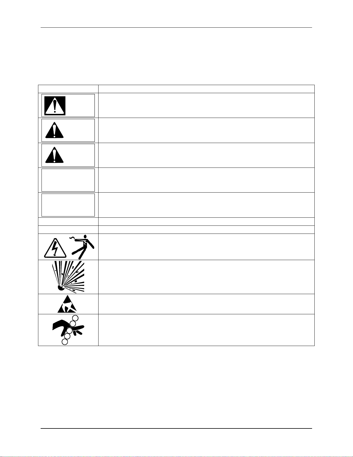
CONVENTIONS AND SYMBOLS
The following symbols may be used in this manual and may appear on the equipment. The reader should become
familiar with the symbols and their meaning. Symbols are provided to quickly alert the reader to safety related text.
Symbol Meaning
Indicates an immediate hazardous situation which, if not avoided, will result in death or
DANGER
WARNING
CAUTION
CAUTION
NOTICE
IMPORTANT
Note
serious injury.
Indicates a potentially hazardous situation which, if not avoided, could result in death or
serious injury.
Indicates a potentially hazardous situation which, if not avoided, may result in minor or
moderate injury.
Indicates a potentially hazardous situation which, if not avoided, may result in property
damage.
Indicates a potential situation which, if not avoided, may result in an undesirable result or
state.
Identifies an action that should be taken to avoid an undesirable result or state.
Identifies supplemental information that should be read before proceeding.
Electrical shock hazard – Either symbol indicates the presence of an electrical shock
hazard. The associated text states the nature of the hazard.
Explosion hazard – Symbol indicates that the danger of an explosion hazard exists. The
associated text states the nature of the hazard.
Electrostatic discharge – The presence of this symbol indicates that electrostatic
discharge can damage the electronic assembly.
Pinch hazard – Symbol indicates that a pinch hazard exists if correct procedures are not
followed.
QUALIFIED PERSONS
The described equipment should be installed, configured, operated, and serviced only by qualified persons thoroughly familiar
with this manual. A copy of this manual is supplied with the equipment. The current version of the manual, in Portable Document
Format (PDF), can be downloaded from the Siemens Internet site; see Product Support in this manual.
For the purpose of this manual and product labels, a qualified person is one who is familiar with the installation, assembly,
commissioning, and operation of the product, and who has the appropriate qualifications for said activities such as:
• Training, instruction, or authorization to operate and maintain devices/systems according to the safety standards for
electrical circuits, high pressures, and corrosive, as well as, critical media.
May 2007
2
Page 5
IGWiPS200-1
• For devices with explosion protection: training, instruction or authorization to work on electrical circuits for systems that
could cause explosions.
• Training or instruction according to the safety standards in the care and use of suitable safety equipment.
SCOPE
This manual does not purport to cover all details or variations in equipment or to provide for every possible
contingency to be met in connection with installation, operation, or maintenance. Should further information be
desired or should particular problems arise which are not covered sufficiently for the purchaser’s purposes, the
matter should be referred to a support group listed in the Product Support section of this manual.
The contents of this manual shall not become part of or modify any prior or existing agreement, commitment or
relationship. The sales contract contains the entire obligation of Siemens. The warranty contained in the contract
between the parties is the sole warranty of Siemens. Any statements continued herein do not create new warranties
or modify the existing warranty.
General Warnings and Cautions
WARNING
An explosion-proof device may be opened only after power is removed from the device.
An intrinsically safe device loses its license as soon as it is operated in a circuit that does not meet the requirements
of the examination certificate valid in your country.
The device may be operated with high pressure and corrosive media. Therefore, serious injury and/or considerable
material damage cannot be ruled out in the event of handling of the device.
The perfect and safe operation of the equipment is conditional upon proper transport, storage, installation and
assembly, as well as, on careful operation and commissioning.
The equipment may be used only for the purposes specified in this manual.
CAUTION
Electrostatic discharge can damage or cause the failure of semiconductor devices such as integrated
circuits and transistors. The symbol at right appears on a circuit board or other electronic assembly to
indicate that special handling precautions are needed.
• A properly grounded conductive wrist or heel strap must be worn whenever an electronics module
or circuit board is handled or touched. Static control kits are available from most electrical or electronic supply
companies.
• Electronic assemblies must be stored in static protective bags when not installed in equipment.
Changes for Revision 3, May 2007
Figure 1 updated.
Product Support section updated.
Analog output wiring for a loop power external device added. See Figures 9 and 10.
RF Link contact rating added to Specifications.
May 2007 3
Page 6
IGWiPS200-1
INTRODUCTION
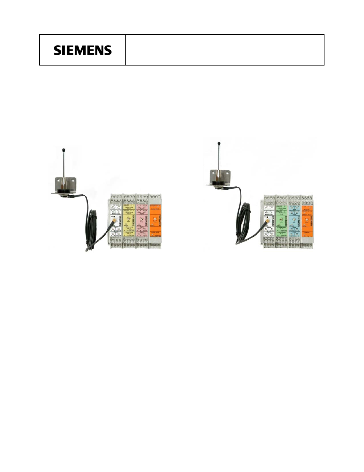
This publication describes installation of the Siemens Wireless
Process Solution (WiPS) 200 Series Two-Way Multipoint-To-Point
Radios and I/O Expansion Modules. Radios (i.e. transceivers)
I/O modules are used to construct a WiPS wireless network for the
gathering and distribution of process related analog, digital, and
pulse/frequency data. Table 1, on the next page, identifies each
WiPS 200 Series model. The table also provides a description of
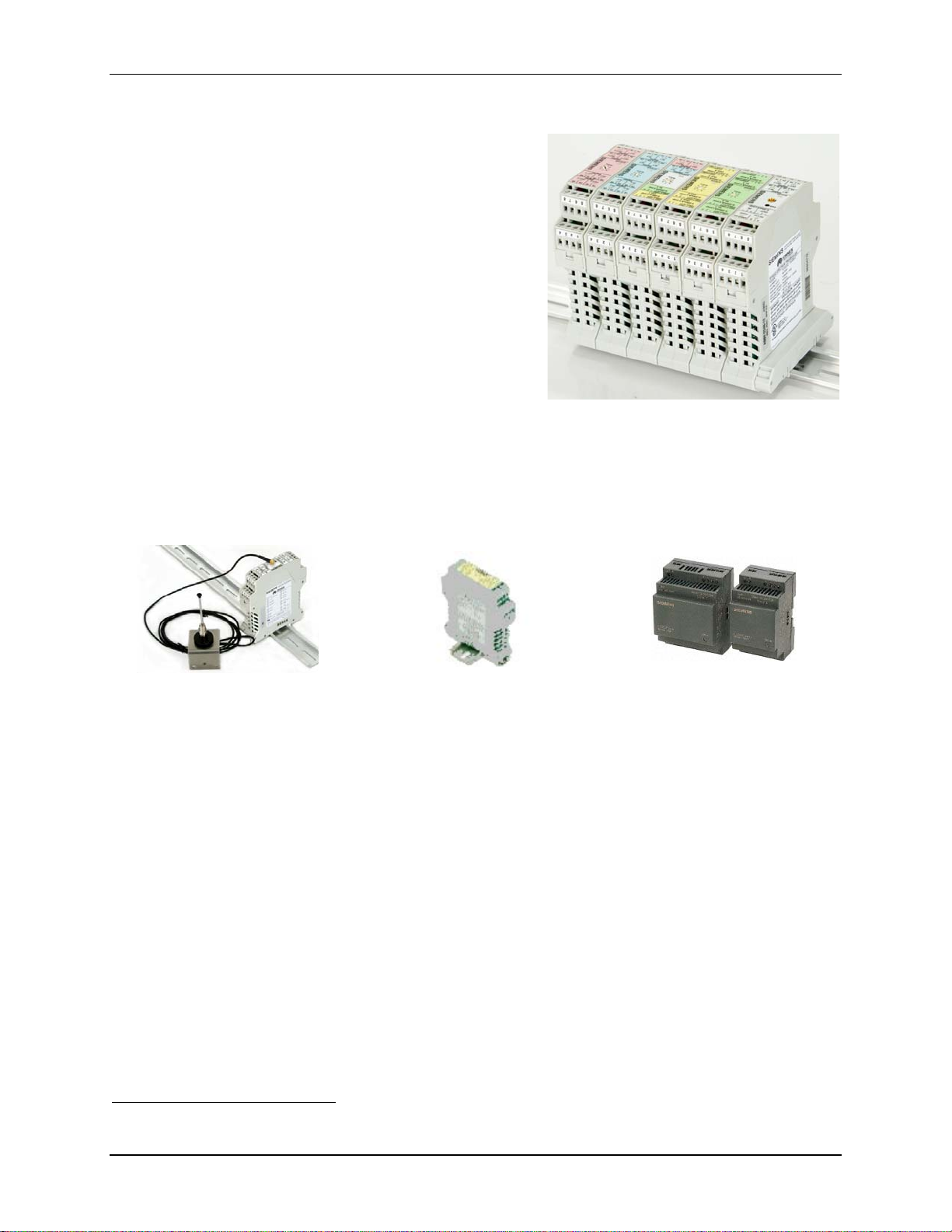
each item and an order/part number. Shown at right are a
transceiver, the right-most module, and five I/O modules mounted
on a section of DIN rail.
A WiPS wireless network is built using a selection of transceivers,
I/O Expansion modules, and accessories, such as antennas, antenna
cables, and power supplies. Transceivers perform two-way wireless
communications. They also have I/O capability with one analog
input channel, one analog output channel, two digital input channels, and two digital output channels. I/O Expansion
modules perform the bulk of the process data gathering and distribution. A selection of modules is available to
accommodate analog, digital, and pulse/frequency data. Antenna selections include a wide range of omnidirectional
and Yagi directional models. These antennas can be paired with low loss antenna cable to further improve
transmitted signal strength allowing communication over longer distances. Siemens Logo power supplies are
available to power transceivers and I/O Expansion modules. Other accessories include surge voltage protection
adapters and cable connector adapters.
1
and
Transceiver with 1/4-Wave Antenna Typical I/O Expansion Module Siemens Logo Power Supplies
Two types of transceivers are provided: Master and Remote (i.e. Slave
2
). The master transceiver is installed at a
central data collection and processing location, such as a control room. Remote transceivers are installed near field
devices, such as transmitters, counters, motors, fans, conveyer belts, stirrers, and annunciators. Each wireless
network must have one master transceiver and at least one remote transceiver. Up to eight remote transceivers can
be installed on a network allowing access to widely distributed field devices.
Table 1 lists the seven types of WiPS I/O Expansion modules and their model and order numbers. I/O Expansion
modules are added to the wireless network’s Master and Remote transceivers in complementary pairs. Up to eight
I/O Expansion modules of any combination can be connected to a Master transceiver. Eight complementary I/O
Expansion modules can then be connected to up to eight remote transceivers. Thus a total of sixteen modules can be
connected to your WiPS wireless network. As mentioned above, I/O Expansion modules are added to the network in
complementary pairs:
• An input module at the Master transceiver must be complemented by an output module of the same type at a
remote transceiver.
• An output module at the Master transceiver must be complemented by an input module of the same type at a
remote transceiver.
The network can accommodate a maximum of 32 analog signals or 64 digital signals or 16 pulse signals or a
combination of analog, digital, and pulse signals (total of inputs or outputs, not the sum of input and outputs).
1
The terms radio and transceiver are used interchangeably in this guide.
2
The terms remote and slave are used interchangeably in this guide.
May 2007
4
Page 7

IGWiPS200-1
Each transceiver and each I/O Expansion module has bus connectors on both sides of its cover: a male connector on
one side, a female connector on the other. A transceiver and several I/O Expansion modules can be physically
interconnected by way of their bus connectors and then snapped onto a section of DIN rail as a single unit. These
bus connectors carry signal, power, and ground connections between the interconnected devices.
An easy to use wireless network Configurator is available at the Siemens Internet site to help you select remote
transceivers and I/O expansion modules. A master transceiver and one remote transceiver are the configuration
starting point. When adding an I/O module to a remote transducer, the complementary module is automatically
added to the master transceiver. For example, adding an 8-Channel Digital Input Module to a remote transceiver will
cause an 8-Channel Digital Output Module to be automatically added to the master transceiver. The online
Configurator totals the number of I/O Expansion modules and displays a warning if the maximum quantity is
exceeded.
Table 1 WiPS Series 200 Multipoint-To-Point Transceivers and I/O Expansion Modules
WiPS Model
Number
Transceiver and I/O Expansion Modules
(see Notes below)
Order
Number
WiPS-20 Unconfigured Transceiver TGX:16347-320
WiPS-22 8-Channel Digital Input Module TGX:16347-322
WiPS-23 8-Channel Digital Output Module TGX:16347-323
WiPS-24 4-Channel Analog Input Module TGX:16347-324
WiPS-25 4-Channel Analog Output Module TGX:16347-325
Combination Input/Output Module with: WiPS-26
TGX:16347-326
1 analog input channel
1 analog output channel
2 digital input channels
2 digital output channels
WiPS-27 2-Channel Pulse Input Module TGX:16347-327
WiPS-28 2-Channel Pulse Output Module TGX:16347-328
Notes:
Order antennas, antenna cable, power supplies, and other accessories separately.
Siemens Logo power supply is part number 6EP13311SH02.
All 200 Series transceivers and I/O Expansion module have bus connectors for distribution of power and data.
A WiPS Series 200 transceiver is a frequency hopping spread spectrum radio designed for professional installation
and integration with other products. When installed with an approved antenna and cable, the system integrator needs
to make sure that the unit’s FCC label is clearly visible on the outside of the integrated product. WiPS is approved
within the 902 to 928 MHz ISM band under 47CFR15.247 of the FCC Rules and Regulations.
Frequency hopping spread spectrum technology was originally developed by the U.S. military to prevent
interference or interception of radio transmissions on the battlefield. Frequency hopping devices concentrate their
full power into a very narrow signal and randomly hop from one frequency to another within a designated frequency
band. If they encounter interference on a particular frequency, the devices error-check the affected data, hop to
another point on the spectrum, and resume communications on subsequent hops. Since there are always spaces
without interference somewhere in the allotted radio spectrum, a frequency hopping device will use those spaces to
complete a transmission.
IMPORTANT
Save this Installation Guide and have it available when installing the above products.
May 2007 5
Page 8

IGWiPS200-1
PRODUCT SUPPORT
When contacting Siemens for support:
• Please have complete product information at hand:
• For hardware, this information is provided on the product nameplate
(part number or model number, serial number, and/or version).
• For most software, this information is given in the Help > About
screen.
• If there is a problem with product operation:
• Is the problem intermittent or repeatable? What symptoms have been observed?
• What steps, configuration changes, loop modifications, etc. were performed before the problem
occurred?
• What status messages, error messages, or LED indications are displayed?
• What troubleshooting steps have been performed?
• Is the installation environment (e.g. temperature, humidity) within the product’s specified operating
parameters? For software, does the PC meet or exceed the minimum requirements (e.g. processor,
memory, operating system)?
• A copy of the product Service Instruction, User’s Manual or other technical publication should be at hand. The
Siemens public Internet site (see the table below) has current revisions of technical publications, in Portable
Document Format, for downloading.
• To send an instrument to Siemens for repair, contact Siemens and request a Return Material Authorization
(RMA).
IMPORTANT
An instrument must be thoroughly cleaned (decontaminated) to remove any process
materials, hazardous materials, or blood born pathogens prior to return for repair. Read and
complete the Siemens RMA form(s).
Contact Information
Telephone +1 800 333 7421
United States
of America
For customer/product support, visit the Siemens Process Instrumentation product support page at
http://www2.sea.siemens.com/Products/Process-Instrumentation/Support/Customer-Support.htm. Select the desired
type of support (e.g. Sales, Technical).
The current revision of this publication and other Siemens WiPS technical publications can be found at
http://www2.sea.siemens.com/Products/Process-Instrumentation/Wireless-Solutions/Wireless+Solutions.htm. Click
on the WiPS series interest (i.e. 100, 200, or 300). The publications are in Portable Document Format (PDF).
Public Internet Site http://www2.sea.siemens.com/Products/Process-
Instrumentation
Repair Service +1 215 646 7400 extension 3187
May 2007
6
Page 9
IGWiPS200-1
INSTALLATION
This section provides installation procedures for a WiPS 200 Series wireless network. A wireless network contains a
master transceiver and up to eight remote (i.e. slave) transceivers. I/O Expansion modules provide the network with
additional analog, digital, and pulse I/O capacity. Transceivers and I/O modules are mounted on user-supplied DIN
rail by the installer. Accessories include antennas (omnidirectional and directional as needed), low-loss antenna
cables, connector adapters, voltage transient suppression adapters, and power supplies.
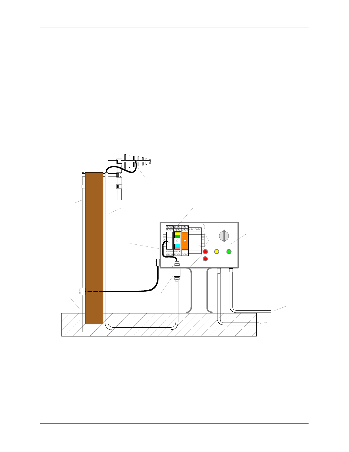
A sample installation is shown in Figure 1. It shows a DIN-rail mounted transceiver and two I/O modules located in
a NEMA 4X rated enclosure. Note the use of a single-point ground system to prevent undesired ground loop
currents. Installation of user-supplied DIN rail and transceiver and I/O modules is discussed later in this section.
The highly directional Yagi antenna, shown below, is used when data transmission over longer distances is
necessary. An omnidirectional whip antenna is used for shorter distances and when a circular radiation pattern is
desired, often due to the wide physical distribution of remote transceivers. Regardless of antenna type, a surge
arrestor is highly recommended, particularly in out-of-doors installations, to protect the connected transceiver from
very large voltages induced by lightning strikes and other electromagnetic events.
Directional Yagi antenna and mounting hardware shown.
Omnidirectional antennas also available.
Grounding
Cable & Rod
Used with
a nonconductive
structure
(wood pole).
Single
Point
Ground
Optional pigtail
Pole
adapter - Type-N
to MCX
Optional COAXTRAB
surge arrester - type-N
connectors
Cable
(LMR400)
Figure 1 Sample Installation
DIN Rail with Transceiver, I/O Expansion
Modules and Logo power supply.
ON
OFF
User-Supplied
NEMA 4X Enclosure
with Operator
Controls
Signal and data
wiring to PLC
or field devices
AC Power
to Logo
power supply
MG00496a
May 2007 7
Page 10
IGWiPS200-1
DANGER
Electrical shock hazard
Explosion hazard
Will cause death or injury.
• Remove power from all wires and terminals before working on
equipment.
• In a potentially hazardous atmosphere, remove power from equipment
before connecting or disconnecting power, signal, or other circuit.
• Observe all pertinent regulation regarding installation in hazardous area.
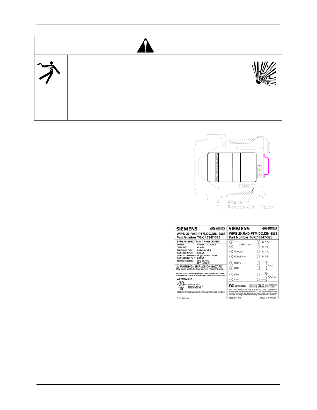
Matched Transceivers
When WiPS transceivers (see Table 1) are ordered, a master transceiver
and up to eight matched remote (i.e. slave) transceivers are supplied.
These transceivers will communicate only with each other.
3
Matched
transceivers have ID labels with the same five digit number. A master
transceiver ID will have an “M” suffix; a remote transceiver will have
an “S” suffix. See the adjacent figure.
Note
When installing several wireless networks, keep track of the
matched transceivers to insure that the proper data is
delivered to the intended controller, PLC, recorder, or field
device.
Nameplate and Wiring Labels
Each transceiver and I/O module has a nameplate label and a
wiring label. The nameplate label carries the module’s part
number, agency approvals, and other data. The wiring label
identifies the connection terminals. Sample labels are shown
here.
To assist module identification, color coded faceplate labels are
provided.
Transceiver – White
4-Channel Analog Input – Green
4-Channel Analog Output – Yellow
8-Channel Digital Input – Blue
8-Channel Digital Output – Pink
Combination Module – Multicolored, by signal type
Pulse Input and Pulse Output – Orange
FCC RULES AND COMPLIANCE
This device complies with 47CFR15.247 of the FCC Rules. Operation is subject to the following two conditions: (1)
This device may not cause harmful interference, and (2) this device must accept any interference received, including
interference that may cause undesired operation.
3
Each transceiver has an internal Hop Key. All transceivers on a WiPS wireless network must have factory programmed Hop
Keys with identical programming allowing them to communicate and exchange data. Hop Keys contain the electronic identifier
and the unique frequency hopping pattern for the transceivers on that WiPS wireless network. For additional details, see Adding
an Extra or Spare Transceiver to Your System later in this Guide.
May 2007
8
Page 11

IGWiPS200-1
Changes or modifications not expressly approved by Siemens will void the user’s authority to operate the
equipment.
This product is intended for fixed installation applications. In order to comply with FCC/ISC adopted RF exposure
requirements, installation of this transmitter system’s antenna must be performed in a manner that will provide at
least a six foot (2m) clearance from the front radiating aperture to any user or member of the public.
FCC 47CFR15.247
ISC RSS 210
UL Class I, Div. 2 (Groups A,B,C,D)
CSA HAZARDOUS LOCATION PRECAUTIONS
This section provides CSA hazardous location precautions that should be observed by the user when installing or
servicing the equipment described in this Instruction. These statements supplement those given in the preceding
section.
Precautions - English
For Class I, Division 2 hazardous locations:
• Use only factory-authorized replacement parts. Substitution of components can impair the suitability of this
equipment for hazardous locations.
For Division 2 hazardous locations:
• When the equipment described in this publication in installed without safety barriers, the following precautions
should be observed. Switch off electrical power at its source (in non-hazardous location) before connecting or
disconnecting power, signal, or other wiring.
Précautions - Français
Emplacements dangereux de classe I, division 2:
• Les pièces de rechange doivent être autorisées par l'usine. Les substitutions peuvent rendre cet appareil
impropre à l'utilisation dans les emplacements dangereux.
Emplacement dangereux de division 2:
• Lorsque l'appareil décrit dans la notice ci-jointe est installé sans barrières de sécurité, on doit couper
l'alimentation électrique a la source (hors de l'emplacement dangereux) avant d'effectuer les opérations
suivantes branchment ou débranchement d'un circuit de puissance, de signalisation ou autre.
ENVIRONMENTAL CONSIDERATIONS
Operate each device within its environmental specifications to help ensure reliable, trouble-free operation with
minimum down time. Refer to the Specifications section for operating temperatures limits, operating humidity, and
maximum moisture content.
CAUTION
Exceeding the specified operating temperature limits can adversely affect performance and
may cause damage to the instrument.
May 2007 9
Page 12

IGWiPS200-1
ANTENNA CONNECTORS AND SURGE VOLTAGE PROTECTI ON
Each transceiver has an MCX female antenna connector. The base 3-1/2", 1/4-wave whip antenna has an MCX male
connector. Optional higher gain antennas and low-loss coaxial cables have type-N connectors. MCX to type-N
adapters and other connector adapters are available. Optional antennas may be accompanied by additional
installation instructions.
If an antenna will be installed out-of-doors or otherwise exposed to surge voltages or strong electromagnetic fields,
such as from a nearby lightning strike, a COAXTRAB Surge Voltage Protection Adapter should be included in the
installation; see Figure 1 for a typical installation. The adapter features a user replaceable gas arrestor tube that
shunts induced high voltage to ground to help protect the transceiver.
Type-N connectors are provided on the adapter; the genders of the two adapter connectors are specified by the
adapter part number. Mount the surge adapter through a bulkhead, through the wall of an enclosure (as shown in
Figure 1), in-line with the antenna cable, on the supplied straight bracket, or on a user-fabricated bracket. Installation
instructions are supplied with the adapter.
CURRENT (AMPERAGE) BUDGET CALCULATION
A common current bus interconnects a transceiver and its connected I/O modules; see Figure 2. The current on this
bus may not exceed 5A. This section shows how to calculate the current flowing on the common current bus. Note
that the calculations in this section are also useful when determining power supply requirements at each transceiver
location.
Figure 2 shows a two-node (remote site and control room) wireless network. The remote site has a remote
transceiver, two input modules, and a power supply. The master transceiver is installed at a control room with two
complementary output modules and a power supply.
The bus current at each transceiver location is calculated by summing the current requirements for the transceiver
and all connected I/O modules. Table 2 lists the current requirements of each module type.
Power Supply
Remote Transceiver
Analog Input Module,
Address 1
Digital Input Module,
Address 2
Power Supply
Master Transceiver
Analog Output Module,
Address 1
Digital Output Module,
Address 2
MG00430a
Remote Site
Common
Current Bus
Control Room
Common
Current Bus
Figure 2 Current (Amperage) Budget Example
Remote Site
As shown in Figure 2, the remote site has one remote transceiver, one analog input module, and one digital input
module. Table 2 shows that the transceiver draws 75 mA, the digital input module 26 mA, and the analog input
module 32 mA plus 20 mA per active channel. The total current (I
) requirement is:
t
It = 75 mA + 26 mA + 32 mA + (4 x 20 mA) = 213 mA
May 2007
10
Page 13

IGWiPS200-1
Control Room
At the control room, there is one master transceiver and complementing I/O: one analog output module, and one
digital output module. The total current requirement is 287 mA [75 mA +100 mA + 32 mA + (4 x 20 mA)].
Table 2 WiPS Module Bus Current Requirements
Module Bus Current Requirement
(in mA @ 24 Vdc)
Transceiver 75 mA average; 200 mA peak*
+ 20 mA per active analog channel
8-Channel Digital Input Expansion Module 26 mA
8-Channel Digital Output Expansion Module 100 mA
4-Channel Analog Input Expansion Module
Module only*
Internal Loop Power**
+ 20 mA per active analog channel
32 mA
4-Channel Analog Output Expansion Module
Module only*
Internal Loop Power**
+ 20 mA per active analog channel
32 mA
Combination Module
Module only*
Internal Loop Power**
+ 20 mA per active analog channel
80 mA
Pulse Input Expansion Module 50 mA
Pulse Output Expansion Module 120 mA
* Base current for module.
** Add 20 mA for each analog channel using internal loop power. Externally powered analog
loops are not added to the calculation.
USER SUPPLIED MATERIALS
A partial list of the materials the user must furnish is provided below. Additional materials may be needed,
depending upon peripheral and accessory equipment and the particular installation.
1. DIN rail(s), mounting hardware, and enclosure(s) appropriate to the environment and hazardous area
certification
2. Signal and power wiring and appropriate tools for wire preparation (e.g. wire cutters and strippers)
3. Conduit tubing, adapters, and outlet boxes and appropriate tools for cutting and routing conduit
4. Circuit protection devices (e.g. fuses, circuit breakers, on-off switches)
Electrostatic Discharge
Semiconductor devices must be protected from electrostatic discharge. A properly grounded conductive
anti-static wrist strap must be worn whenever a circuit board assembly is handled or touched. A service
kit with a wrist strap and static dissipative mat is available from most electronic parts supply companies.
I/O MODULE CONFIGURATION SWITCH SELECTIONS
Configure the following modules before mounting on the DIN rail.4 Field settable switches are provided module
configuration. Default settings are provided.
• 4-Channel Analog Output Module (See Figure 13 on page 23 and paragraph A below.)
• 8-Channel Digital Output Module (See Figure 15 on page 24 and paragraph A below.)
• Combination Input/Output Module (See Figure 16 on page 25 and paragraph A below.)
• 2-Channel Pulse Input Module (See Figure 17 on page 26 and paragraph B below.)
• 2-Channel Pulse Output Module (See Figure 18 on page 26 and paragraph B below.)
4
A module may be configured after installation. However, access to switches may be impeded by adjacent modules.
May 2007 11
Page 14

IGWiPS200-1
A. Analog Output and Digital Output Fault Response Selections
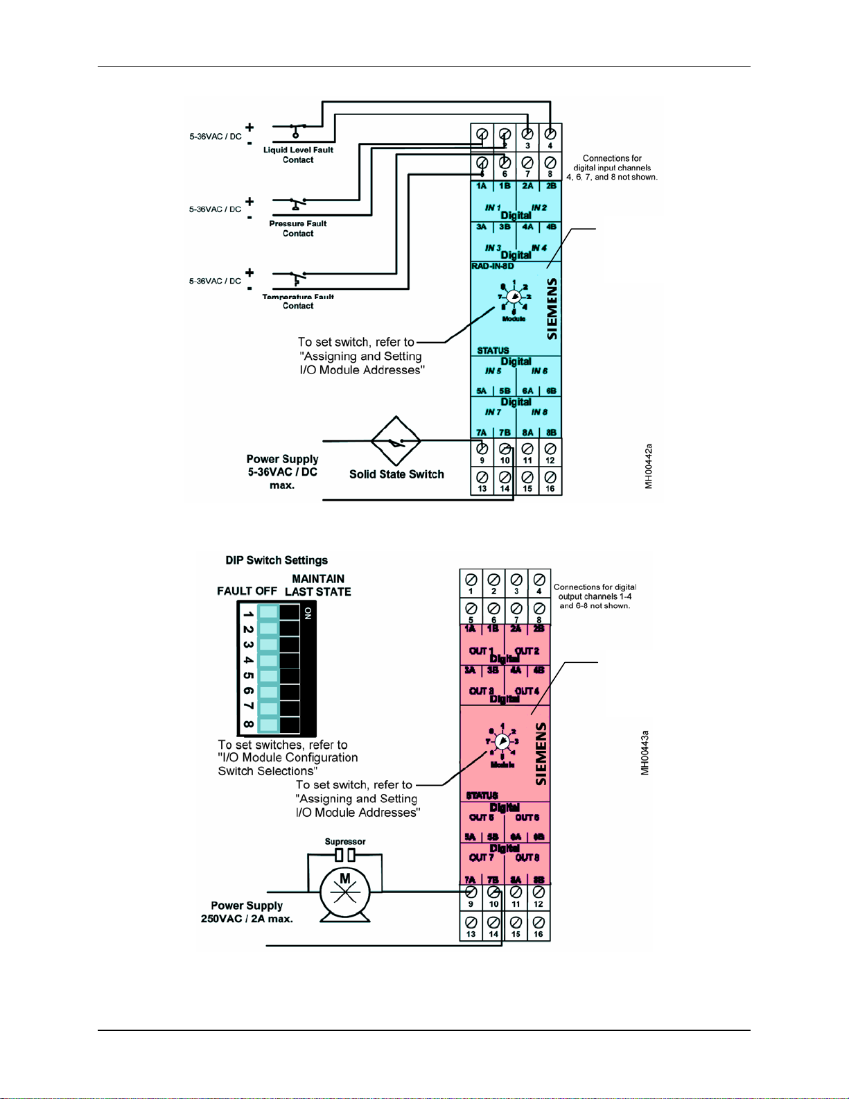
Three I/O modules (4-Channel Analog Output Module, 8-Channel Digital Output Module, and Combination
Input/Output Module) contain DIP switches that may be set by the user to determine the module’s response to the
connected transceiver’s loss of an RF Link or to the loss of an input signal. There is a DIP switch for each signal
channel allowing individual programming of each channel. See Figures 13, 15, and 16 on pages 23, 24, and 25
respectively.
When a loss of RF Link or signal occurs:
• If the DIP switch is set to ON, the default setting, the output from that channel will MAINTAIN LAST STATE.
• If the DIP switch is set to OFF, the output from an analog channel will be 2 mA; the output from a digital
channel will be OFF.
Refer to paragraph C to set the DIP switches.
B. Pulse Input and Pulse Output Mode of Operation Selections
The 2-Channel Pulse Input Module has five sliding-shunt switches, the complementary 2-Channel Pulse Output
Module has four DIP switches. Several switches are used to select mode of operation: counter or frequency. Others
allow selection of coupling, impedance, speed, and sensor input. Setting for Pulse Input and Pulse Output Modules
are detailed below. Refer to paragraph C to set the switches.
Pulse Input Module (See Figure 17 on page 26)
Switch 1 Coupling – AC or DC; Default setting is AC
Set the jumper to AC Coupling if the pulse voltage will never drop below 3.6V with respect to the
transceivers power supply negative. This would apply where there is a DC bias voltage added to the pulse
input voltage, where the DC bias exceeds 3.6V such as in a ground loop condition. All other applications,
including an AC sine wave input, should be set to DC Coupling.
Switch 2 Input Impedance – Low or High; Default setting is High
The Low impedance setting has an input impedance of 1K Ohm and the High setting has an impedance of
90K Ohm. Use the High impedance setting for magnetic transducers to prevent the current draw from
dropping the voltage below the 100 mVAC peak-to-peak minimum. Use the Low impedance setting for
digital and relay interfaces because the additional current draw will prevent electrical noise from causing
false pulse counts.
Switch 3 Operation – Counter or Frequency; Default setting is Counter
Pulse input values are stored in the PLC register in either of two formats: an absolute count of the number of
pulses, which will require that the register be reset periodically to prevent overflow, or a frequency value.
The frequency setting will take the average number of pulses every second.
Switch 4 Speed – Low or High; Default setting is High
The Low speed pulse setting is for a maximum input frequency of 2 Hz with a minimum pulse width of 70
ms. The High speed setting is designed for pulse frequencies up to 32 kHz and requires a minimum pulse
width of 10 microseconds. Use the Low speed setting for mechanical pulse generating devices such as relays
and the high speed setting for all other applications. The Low speed setting prevents contact bounce from
being recorded as pulses.
Switch 5 Sensor Input – Single Ended (Common Mode) or Differential Mode; Default setting is Single
Ended
If the pulse signal is expected to be of negative polarity, with respect to ground, set the module to Differential
mode, whereas if the signal will remain positive at all times, set it to Single Ended (Common Mode).
May 2007
12
Page 15

IGWiPS200-1
Pulse Output Module (See Figure 18 on page 26)
There are two DIP switches for each channel: switches 1 and 2 for channel 1, switches 3 and 4 for channel 2.
Switches 1 (CH1) and 3 (CH2) – Counter or Frequency Mode; Default setting is Counter
When Counter mode is selected, the module will output a specific number of pulses as determined by the
PLC value written to it by the Pulse Input Module. If Frequency mode is selected, the pulse output module
will generate pulses in accordance with the desired frequency, with a 50% duty cycle. In Frequency mode,
the low or high speed switch setting below is ignored.
Switches 2 (CH1) and 4 (CH2) – Low or High Speed Operation; Default setti ng is Hi gh
Set this switch when the channel is set to Counter mode; see preceding paragraph. If High speed is selected
the pulses will be sent at a frequency of 10 kHz with a 50% duty cycle. If Low speed is selected the pulses
will be sent at a frequency of 10 Hz also with a 50% duty cycle.
C. Setting Module Switches
Perform the following steps to change switches from default settings.
1. Place an anti-static wrist strap on your wrist and connect the strap’s ground lead to a good ground. If
the module to be configured is installed on DIN rail, go to step 2; if it has not been installed, go the
step 3.
2. Remove power and signal from the transceiver and all I/O modules, if the module is installed and wired.
At the module to be configured, remove the wired connector block(s) from the module; see Figure 5 on page 17
for photographs (alternatively, label each wire to facilitate reconnection and then disconnect the wires).
Physically separate interconnected modules to disconnect the common current bus connectors. Use a small
straight slot screwdriver to lever the spring-loaded module mounting lip away from the DIN rail allowing that
module to slide on the rail. Remove the module from the DIN rail.
3. Remove the faceplate/circuit board assembly by locating a rectangular recess near the numbered terminals on
the top of the module cover; see the photographs below and Figure 4 on page 15. With a small flat blade
screwdriver, press the tab in the recess inward and pull that corner of the faceplate outward slightly. Repeat this
process at the bottom of the module. Carefully pull the faceplate/circuit board assembly from the cover.
4. Locate the module at hand in Figures 12 through 18 on pages 23 through 26. Set the switches as described in the
appropriate preceding paragraph and figure.
5. Press the faceplate ribbon cable into the module and carefully insert the circuit board into its cover until it snaps
into place. When inserting the circuit board into its cover, be sure the circuit board engages the card guides in
the cover and that the circuit board card edge connector mates with the connector in the cover.
6. If the module was removed from DIN rail in step 2, install the module on the rail. Fully insert the connector
blocks (or connect removed wires).
7. Repeat the above steps for each module containing switches.
8. Remove the anti-static wrist strap from your wrist and install the DIN rail and module(s).
Press Tab
Faceplate /
Circuit Board
Assembly
in Recess
at Top
then at
Bottom
May 2007 13
Page 16

IGWiPS200-1
MOUNTING THE DIN RAIL
At each installation site, mount the DIN rail and DIN rail mount modules (e.g. transceiver, I/O modules, power
supply) in a NEMA enclosure appropriate for the environment and hazardous area classification. Refer to Figure 3
for transceiver and I/O module dimensions. Allow room for:
o Physically mounting and wiring the modules and for antenna, power, ground and signal wire runs
o Accessories (e.g. low loss cable and MCX to N-type connector adapter, surge voltage protection adapter)
o Conduit adapters
o Operator controls
o Circuit protection/safety devices (e.g. switches, circuit breakers, or fuses)
o Other items as determined by the installer/user.
Fasten the DIN rail to a rigid panel within the enclosure using user-supplied hardware. An enclosure is required in a
hazardous area installation. In a non-hazardous area, a secure enclosure can provide safety for area personnel and it
restricts access to the equipment.
IMPORTANT
The DIN rail must be grounded. When mounting the DIN rail in a non-conductive
enclosure, install a ground wire between the rail and the single point ground.
DIN Rail Mount Transceiver or I/O Expansion Module
Figure 3 Physical Dimensions
MOUNTING A TRANSCEIVER OR I/O MODULE
I/O Expansion Modules may be mounted on a section of DIN rail in any sequence. Mount the Transceiver at either
end of the row of up to 8 I/O modules, to ensure sufficient heat dissipation.
IMPORTANT
If a module contains configuration switches that have not been set, refer to I/O Module
Configuration Switch Selections on page 11 before installing the module on DIN rail. A list
of modules with configuration switches is provided in the referenced section.
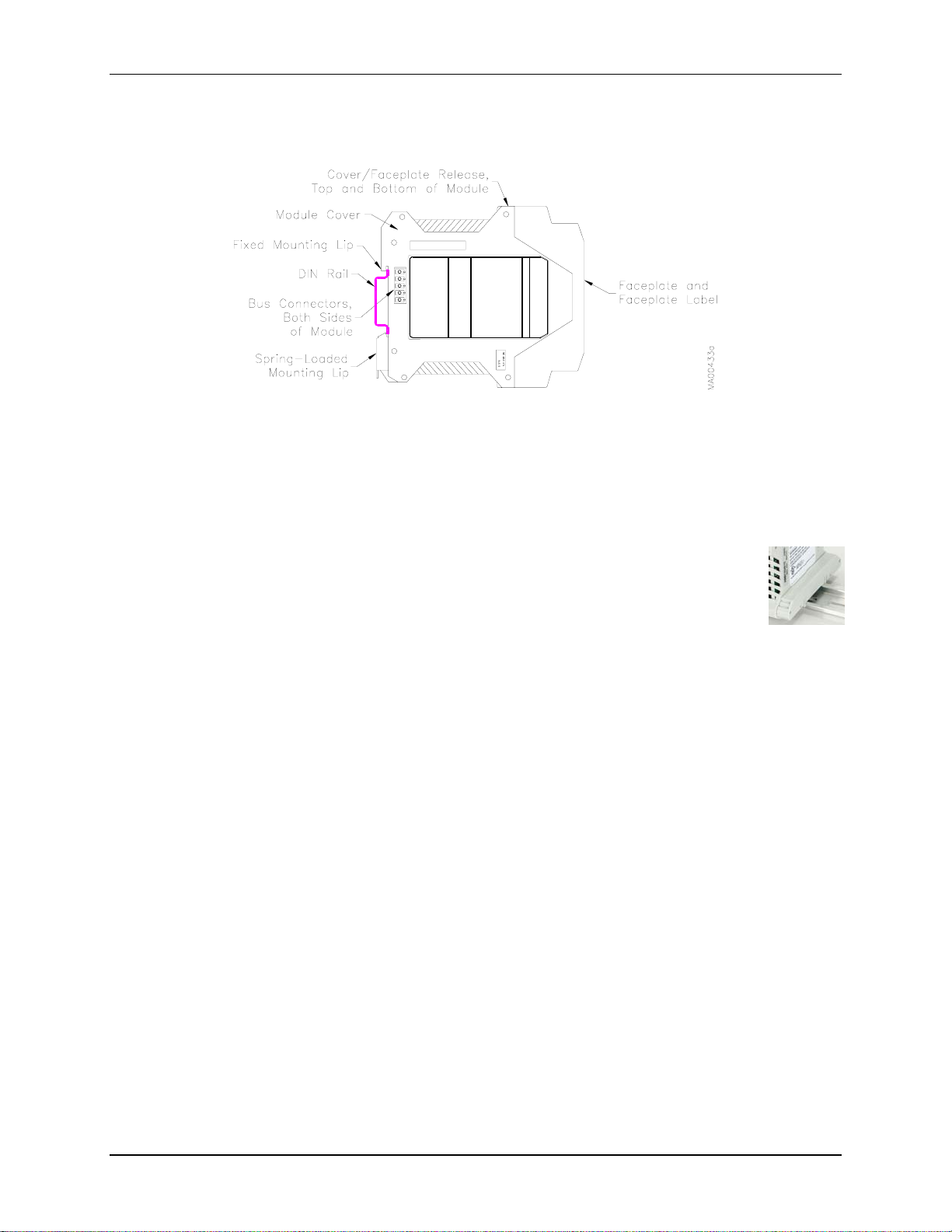
At each installation site, the transceiver and I/O modules are interconnected by built-in bus connectors; see Figure 4
below. Each module has male bus connectors on one side and female bus connectors on the other. When mounting
modules on a DIN rail, be sure to correctly orient modules so they interconnect and the module faceplates are
oriented for easy reading. Refer to the following procedures to install modules.
May 2007
14
Page 17
IGWiPS200-1
Each module has a moveable, spring-loaded mounting lip to assist in mounting a module, sliding a module along the
DIN rail, and removing a module from the DIN rail. This lip has a slotted tab so the blade of a small screwdriver can
be inserted and the lip levered away from the rail.
Figure 4 Module Features
To mount a row of up to 8 modules on a DIN rail:
1. Interconnect the modules by mating the bus connectors.
2. Hook the fixed mounting lips, see Figure 4, on the DIN rail.
3. Press the assembly onto the DIN rail. The spring-loaded mounting lips will snap onto the rail. Do not use
excessive force.
4. A transceiver is supplied with a bus connector cover, shown at right. Place the cover over the
exposed male bus connectors at one end of a group of modules.
To add a module to a row:
1. Note the gender of the installed module’s bus connector.
2. Orient the module and hook the module’s fixed mounting lip on the DIN rail.
3. Press the module against the DIN rail until the spring-loaded mounting lip snaps onto the rail.
4. Slide the module to one side until the bus connector mates with the adjacent module. A module will easily slide
on the DIN rail if the spring-loaded lip is levered away from the rail.
5. As required, place a bus connector cover (supplied with a transceiver) over the exposed male bus connectors at
one end of a group of modules.
To remove a module from the DIN rail:
1. Separate the module to be removed from adjacent modules. To move a module, use a small straight-slot
screwdriver to lever the spring loaded mounting lip slightly away from the rail and slide the module along the
DIN rail until the bus connectors separate. Be sure the bus connectors on both sides of the module to be
removed are fully disengaged from adjacent modules.
2. On the module to be removed, lever the moveable, spring-loaded mounting lip away from the DIN rail. Then
pull the module from the DIN rail.
May 2007 15
Page 18
IGWiPS200-1
MOUNTING THE 1/4-WAVE WHIP ANTENNA
Mount the 3-1/6" (80.4 mm) high, omnidirectional whip antenna5, shown at right, within 5' (1.5m) of the
transceiver to allow the supplied 6' (2m) cable to easily reach between the antenna and transceiver. A
mounting bracket and three screws are supplied. Antenna spacing (transmitter to receiver) should not
exceed 600' to 1000' (183m to 305m). Line of sight is not a requirement.
Incorrect antenna placement and positioning can have a significant impact on the performance of the
system. Keep the omnidirectional antenna vertical and mounted as high as possible.
1. Fasten the supplied right-angle bracket to a rigid, vibration-free surface such that the antenna is oriented
vertically.
2. Unscrew the black disk from the antenna cable end. Insert the antenna cable stud into the large center hole in
the bracket and thread the disk onto the stud. The shallow shoulder on the disk should be toward the bracket
surface. Refer to the cover of this publication.
3. Center the disk in the hole using the shallow shoulder on the disk to assist centering and then tighten the disk.
The supplied hex wrench can be inserted in a hole in the disk perimeter to help tighten the disk. Do not over
tighten. The threaded stud must not be in contact with the grounded bracket.
4. Thread the antenna onto the stud and tighten.
5. Once the transceiver is installed, plug the MCX male connector on the end of the antenna cable into the MCX
female connector on the transceiver faceplate.
WIRING
This section provides wiring guidelines for the transceiver and I/O Expansion modules.
A wireless network contains a master transceiver and up to eight matched remote transceivers. These transceivers
will communicate only with each other. Refer to Installation, Matched Transceivers for additional information.
Before wiring transceivers, confirm that the ID numbers match and that the installed locations are correct. This is
particularly important when installing several wireless networks.
These devices must be wired in accordance with Class 1, Div. 2 wiring methods as described in the National
Electrical Code, Article 501-4(b) or the authority having jurisdiction.
DANGER
Electrical shock hazard
Explosion hazard
Will cause death or injury.
• Remove power from all wires and terminals before working on
equipment.
• In a potentially hazardous atmosphere, remove power from equipment
before connecting or disconnecting power, signal, or other circuit.
• Observe all pertinent regulations regarding installation in a hazardous
area.
5
For other antenna models, refer to the appropriate antenna Data Sheet for specifications and mounting dimensions. Additional
installation information may be provided with the antenna.
May 2007
16
Page 19

IGWiPS200-1
Electrical Connections – Power and I/O connections are completed through screw actuated compression terminals.
Connector blocks can be removed from a module for wiring, as shown in the two figures below. Insert a small
straight-slot screwdriver between a connector block and the faceplate and use a gentle prying motion to separate the
connector block from the module. Each connector in a module is uniquely keyed. When installing a connector block,
be sure to fully insert the block in the module.
Connector
Block
Removed
from Module
Figure 5 Removing a Connector Block
A snap-in MCX female connector is provided for the transceiver antenna connection.
Wire Stripping Recommendations:
Screw terminal wiring - 1/4" (6 mm) to 5/16" (8 mm)
Be careful not to nick the conductor or cut away strands.
Wire Selection - Stranded wire is recommended for most connections. Carefully select wire size, conductor
material, and insulation. Some selection considerations are:
• current and voltage to be carried
• total length of each wire run
• whether wire will be bundled or run singly
• indoor or outdoor installation
• temperature extremes (Use supply wires suitable for 5°C (10°F) above ambient temperature.)
• exposure to sunlight
• vibration
• types of contaminates
Wire Routing and Conduit - DC wiring should be separated from AC wiring and away from AC powered
pushbuttons, alarms, annunciators, motors, solenoids, and similar devices. Conduit and raceways are commonly
used for routing wiring. Wiring not installed in conduit or raceway should be clamped or supported approximately
every 12 inches (300 mm).
Power Input Circuit Protection
A circuit protection device must be installed in the power input circuit between the power source and the WiPS
transceiver or I/O module. Locate the protective device in a non-hazardous area unless suitable for use in a
hazardous area. Circuit protection can be provided by a circuit breaker, fuse or on-off switch accessible to the
operator, except where otherwise stated in this guide or by a certifying agency.
• AC to DC (converter) power supply – Typically, this power supply includes a fuse or circuit breaker in its
output circuit and often includes current limiting. An additional protective device at the module enclosure is
recommended. Check power supply specifications carefully.
• Battery power supply – This power system, because of the large amount of energy stored in a battery, must
include circuit protection.
May 2007 17
Page 20

IGWiPS200-1
Transceiver Wiring Examples
Five transceiver wiring examples are provided below. Figures 6, 7, and 8 show typical transceiver wiring for 2-wire,
3-wire, and 4-wire current loops. Figures 9 and 10 show two variations on the wiring for a loop powered external
analog device. Also shown in Figures 9 and 10 is the wiring for an RF Link annunciator, which can be an input to a
PLC or controller or a separate light or siren. A digital output wiring example is provided in Figure 9.
The transceiver is DC-powered, typically by a DIN rail mount power supply, as shown below. The power supply for
the transceiver also powers the connected I/O modules. Power is supplied through the transceiver and across the
common current bus as shown in Figure 2 on page 10.
Figure 6 Transceiver Wiring, 4-20 mA Current Loop with 2-Wire Device
May 2007
18
Page 21

IGWiPS200-1
Figure 7 Transceiver Wiring, 4-20 mA Current Loop with 3-Wire Device
May 2007 19
Page 22

IGWiPS200-1
Figure 8 Transceiver Wiring, 4-20 mA Current Loop with 4-Wire Device
May 2007
20
Page 23

IGWiPS200-1
Figure 9 Transceiver Wiring, Analog and Digital Outputs
Figure 10 Transceiver Wiring, Analog Output Wiring for a Loop Powered Device
May 2007 21
Page 24

IGWiPS200-1
Transceiver RF Link and Output State Wiring Options
This section describes the transceiver RF link status relay and the analog output and digital output wiring options. A
block diagram of the transceiver is shown in Figure 11.
Figure 11 Transceiver Block Diagram
Transceiver RF Link
The RF Link relay has Form A, Normally Open (NO) contacts that close when the transceiver establishes an RF link
with another transceiver. The contacts are often used to turn on a STATUS light, provide a digital status signal to a
controller or PLC, or mechanically disconnect an analog or digital signal, as described below, when an RF link is
lost. Refer to the Specifications section for relay contact rating.
For additional information about RF Link response, refer to Transceiver and I/O Expansion Module Status LEDs on
page 30.
Transceiver Analog and Digital Output Last State Selection
The default state upon loss of RF link for the analog and digital outputs is MAINTAIN LAST STATE. Either an
analog output or a digital output may be wired in series with the RF Link contact to provide a FAULT OFF status
when an RF link is lost. Refer to the Specifications section for relay contact rating.
I/O Expansion Module Wiring Examples
I/O module wiring connections are shown in Figures 12 through 18 on the following pages.
May 2007
22
Page 25

IGWiPS200-1
Green
Faceplate
Figure 12 4-Channel Analog Input Module Wiring
Yellow
Faceplate
Figure 13 4-Channel Analog Output Module Wiring
May 2007 23
Page 26
IGWiPS200-1
Blue
Faceplate
Figure 14 8-Channel Digital Input Module Wiring
Pink
Faceplate
Figure 15 8-Channel Digital Output Module Wiring
May 2007
24
Page 27

IGWiPS200-1
Multiple
Colors
Faceplate
Figure 16 Combination Input and Output Module Wiring
(One Analog Input, One Analog Output, Two Digital Inputs, and Two Digital Outputs)
May 2007 25
Page 28

IGWiPS200-1
Orange
Faceplate
Figure 17 2-Channel Pulse Input Module Wiring
Orange
Faceplate
Figure 18 2-Channel Pulse Output Module Wiring
May 2007
26
Page 29

IGWiPS200-1
ASSIGNING AND SETTING I/O MODULE ADDRESSES
Module addresses are 1 through 8, as shown on the module faceplates in Figure 19. The top row in the figure shows
three I/O modules at a location (for example, at a remote location). The lower row shows the complementary I/O
modules at another location (for example, at the control room); transceivers are not shown. Note that the modules in
each complementary pair are set to the same address. For example, the Analog Output Module at the remote location
(yellow faceplate) and the complementary Analog Input Module at the control room (green faceplate) are set to
address 1. The small triangle symbol points to the selected module address.
When assigning I/O module addresses:
• Assign a module address to each complementary pair of I/O modules on a wireless network.
• An address may be used for only ONE complementary pair on each wireless network.
If module addresses conflict or are improperly set within a complimentary pair, the STATUS LED will light; see the
Transceiver and I/O Expansion Module Status LED Indications section on page 30.
Yellow
Faceplate
Green
Faceplate
A. Three I/O Modules (Remote Location)
B. Three Complementary I/O Modules (Control Room)
Figure 19 I/O Module Address Selection Switch
May 2007 27
Page 30

IGWiPS200-1
HAZARD LABEL
A label, similar to that shown here, is included in a WiPS shipment. The installer or
user should post this label in an appropriate, highly visible location near the WiPS
modules. Possible label mounting locations include: on the outside of an enclosure
housing WiPS modules or inside that enclosure adjacent to the modules.
ADDING A REMOTE OR SPARE TRANSCEIVER TO YOUR NETWORK
When WiPS transceivers are ordered, two or more transceivers are supplied as
matched devices, meaning that they share the same electronic identifier and
frequency hopping pattern. This data is stored in a Hop Key. The Hop Key in a
transceiver can be removed and physically transferred to another transceiver
producing a second matched transceiver. The original matched transceiver will
retain its Hop Key data and operate normally even though the Key has been
removed.
The following procedure describes transferring the Hop Key from a matched transceiver to an unmatched
transceiver (e.g. spare transceiver part number TGX:16347-320) thereby producing another matched transceiver.
The newly matched transceiver can then be used as a remote transceiver in a multipoint-to-point system, a spare
transceiver, or a replacement (master or remote) transceiver. Once the Hop Key is installed in the transceiver and
power is applied, the transceiver will memorize the identification, hop frequencies, and hop sequence of the matched
transceiver. When power is removed, it will retain this information, even if the Hop Key is removed. The newly
matched transceiver and the original matched transceiver will communicate with the other matched transceiver(s).
IMPORTANT
When replacing or adding a transceiver to a wireless network, remember that a network
node can have one (1) master transceiver and up to eight (8) remote transceivers.
To Transfer a Hop Key
1. Place an anti-static wrist strap on your wrist and connect the strap’s ground lead to a good ground.
2. If the transceiver is installed, remove power from the transceiver and all I/O connections.
Remove the wired connector blocks from the transceiver; see Figure 5 on page 17 for photographs
(alternatively, label each wire to facilitate reconnection and then disconnect the wires). Physically separate any
connected I/O modules and remove the transceiver from the DIN rail.
3. Remove the faceplate/circuit board assembly locating a rectangular recess near the numbered terminals on the
top of the transceiver cover (see Figure 4 on page 17 and Figure 20 below). With a small flat blade screwdriver,
press the tab in the recess inward and pull that corner of the faceplate outward slightly. Repeat this process at
the bottom of the transceiver. Carefully pull the faceplate/circuit board assembly from the cover.
Figure 20 Module Disassembly
May 2007
28
Page 31

IGWiPS200-1
4. Locate the Hop Key (a small circuit board) at the rear edge of the top circuit board, see the figure below.
Unplug the Hop Key and set it aside.
Hop Key
Location
5. Carefully insert the faceplate/circuit board assembly in its cover until it snaps into place. When inserting the
assembly into its cover, be sure the circuit board enters the card guides in the cover and the circuit board card
edge connector mates with the connector in the cover.
6. Remove the spare transceiver’s cover as described above in step 3.
7. Insert the Hop Key from the original transceiver into the spare transceiver - carefully align the Hop Key
connector with the main circuit board pins. Carefully insert the faceplate/circuit board assembly in the enclosure
– review step 5 as needed to ensure correct orientation.
8. Label the spare transceiver with the Hop Key 5-digit ID number and suffix (M for master, S for remote).
9. If replacing the original transceiver, mount the spare transceiver on the DIN rail and complete all needed
connections. Otherwise install the original transceiver and complete all needed connections.
10. Remove the anti-static wrist strap from your wrist.
When power is applied to the “spare” transceiver, it will memorize Hop Key data - allow a few seconds after power
up for the data to transfer to transceiver memory.
POST INSTALLATION SIGNAL STRENGTH AND LED INDICATIONS
This section describes a method for determining whether received signal strength is adequate. It also provides status
LED indications that will help to assess whether the wireless network is operating properly.
There are no user serviceable parts within a transmitter or receiver. Should service be needed, see the Product
Support section to contact Siemens.
TRANSCEIVER RSSI
RSSI (Received Signal Strength Indicator) is measured using a DC voltmeter between the provided test point and
power supply ground. The test point is accessed by inserting a positive meter probe into the RSSI receptacle on the
face of the transceiver module and connecting the negative meter probe to the module’s Ground terminal.
The RSSI graph in Figure 21 can be used to test the received signal strength. Ideally, the meter reading should be 2.5
Vdc or more. This represents a 90 dB signal loss and typically indicates that the transceiver has 20 dB fade margin
left until loss of link. It is recommended that a transceiver be set up with no less than a 20 dB margin.
May 2007 29
Page 32

IGWiPS200-1
RSSI vs DC Voltage
4.0
3.0
2.0
-75
1.0
0.0
MG00446a
+DC Volts
-115 -110
-105
-100
Signal Strength (-dBm)
-95 -90 -85
-80
Figure 21 Received Signal Strength Graph
TRANSCEIVER AND I/O EXPANSION MODULE STATUS LED INDICATIONS
Power LED Indicates the presence of power to the module. It is ON when power is present and OFF when
there is no power.
Status LED When flashing rapidly, it indicates an internal error or a module type mismatch. A module type
mismatch occurs when the module address selection for two different modules (i.e. one digital
modules and one analog module are set to the same address or two pairs of modules are sharing
the same address).
RF Link LED Flashes once every two seconds when there is no RF link.
Note: At the Master transceiver, an RF Link failure will not be indicated by the master
transceiver or the connected I/O Expansion Modules until the master has lost RF Link with
all Remote transceivers. A Remote transceiver will indicate a loss of RF Link when it
cannot communicate with the master transceiver.
Flashes rapidly when signal strength is marginal (see the RSSI graph in the Servicing section of
this guide.
ON steady indicates an exceptionally strong RF link.
Most systems will flash occasionally indicating the presence of intermittent interference in the
area.
Digital
Input/Output
OFF means that the digital input or output circuit is Open.
ON means that the digital input or output circuit is Closed.
PULSE INPUT MODULE DIAGNOSTIC LED’S
There are 4 diagnostic LED’s on the pulse input module:
Status LED: On solid when I/O is functional and flashing if there is a conflict with another module.
Backup Power LED: On solid when the backup power supply is powering the module. Off when primary
power is powering the module.
Pulse Input 1 and 2 LEDs: These lights will flicker at a varying frequency when pulses are applied to each
channel:
Frequency Range (Hz) LED Flashing Frequency (Hz)
1 ≤ frequency ≤ 10
10 < frequency ≤ 100
100 < frequency ≤ 1000
1000 < frequency ≤ 32K
1
4
8
On solid
May 2007
30
Page 33

IGWiPS200-1
PULSE OUTPUT MODULE DIAGNOSTIC LED’S
There are 3 diagnostic LED’s on the pulse output module:
Status LED: On solid when I/O is functional and flashing if there is a conflict with another module.
Pulse Input 1 and 2 LEDs: These lights will flicker at a varying frequency depending on the frequency of
pulses being generated:
Frequency Range (Hz) LED Flashing Frequency (Hz)
1 ≤ frequency ≤ 10
10 < frequency ≤ 100
100 < frequency ≤ 1000
1000 < frequency ≤ 32K
1
4
8
On solid
SPECIFICATIONS
Transceiver
Frequency .............................................................902 to 928 MHz industrial, scientific, and medical (ISM) band
Technology...........................................................Frequency Hopping Spread Spectrum
Power Input ..........................................................9-30 Vdc; reverse polarity and surge protected
Power Consumption .............................................75 mA (average), 200 mA (peak) @ 24 Vdc during transmission
(plus I/O modules), 5A (maximum)
Inputs
Analog ...........................................................1, 4 to 20 mA (16-bit, 125 Ohms impedance
Digital............................................................2, 5 to 36 Vac/Vdc (for 120 Vac digital inputs use relays to convert
to specified voltage levels; consult factory for relay options)
Outputs
Analog ...........................................................1, 4 to 20 mA, 12-bit resolution, short circuit protected
Digital............................................................2, 250 Vac / 30 Vdc, 2A dry contact
RF Link .........................................................1, 250 Vac / 30 Vdc, 2A dry contact
Repeatability (4-20 mA Current Loop) ................0.02%
Accuracy (4-20 mA Current Loop) ......................0.2% full scale
Transmitter Power Output ....................................1 Watt (30 dBm)
Range
Standard Omnidirectional Antenna ...............600 to 1000 feet (183m to 305m) in-plant, obstructed LOS
Optional Omnidirectional Antenna ...............4 to 5 miles (6.5 km to 8 km) clear LOS, flat terrain, raised antenna
Optional Yagi Antenna..................................15 to 20 miles (24 km to 32 km) clear LOS, flat terrain,
professional propagation study and installation
Antenna Connector...............................................MCX female, 50 Ohms
Operating Temperature Range..............................-40°C to 70°C (-40°F to 158°F)
Humidity...............................................................20% to 90% non-condensing
Dimensions...........................................................4.5" x 3.9" x 0.9" (114 mm x 99 mm x23 mm)
Faceplate Label Color...........................................White
Weight ..................................................................5.3 oz (150g)
Environmental ......................................................NEMA 1, equivalent to IP 20
Approvals
USA...............................................................FCC 47CFR15.247
Canada...........................................................ISC RSS 210
UL and CUL..................................................Class I, Div. 2, Groups A, B, C, D; Temp. Code T5
CSA ...............................................................Approved
6
6
LOS – Line of Sight between transmitting and receiving antennas
May 2007 31
Page 34

IGWiPS200-1
Digital Input Module
Channels ...............................................................8
Digital Input Voltage Range.................................5 to 30 Vac/Vdc, reverse polarity protected
Input Impedance ...................................................20k Ohms
Input Frequency....................................................DC to 2 Hz
Channel Isolation..................................................Optical
Over-Voltage Rating.............................................100 Vac/Vdc maximum
Power Input ..........................................................12-30 Vdc
Current Consumption ...........................................30 mA maximum
Operating Temperature Range..............................-40°C to 70°C (-40°F to 158°F)
Faceplate Label Color...........................................Blue
Digital (Relay) Output Module
Channels ...............................................................8
Output Terminal ...................................................Dry Contact, normally open
Contact Rating ......................................................250 Vac / 30 Vdc, 2A
Channel Isolation..................................................Full
Power Input ..........................................................12-30 Vdc
Current Consumption ...........................................160 mA maximum
Operating Temperature Range..............................-40°C to 70°C (-40°F to 158°F)
Faceplate Label Color...........................................Pink
Analog Input Module
Channels ...............................................................4
Range....................................................................4-20 mA
Resolution.............................................................16-bit
Input Impedance ...................................................<170 Ohms
Channel Isolation..................................................None (power supply connections are common with transceivers)
Reverse Polarity Protected....................................Yes
Compatibility........................................................2-wire, 3-wire, 4-wire devices
Over-Voltage Rating.............................................42 Vdc maximum
Accuracy...............................................................0.2% of full scale
Repeatability.........................................................0.02% of full scale
Power Input ..........................................................12-30 Vdc
Current Consumption ...........................................130 mA maximum
Operating Temperature Range..............................-40°C to 70°C (-40°F to 158°F)
Faceplate Label Color...........................................Green
Analog Output Module
Channels ...............................................................4
Range....................................................................4-20 mA
Resolution.............................................................16-bit
Channel Isolation..................................................Optical
Short Circuit Protected .........................................Yes
Compatibility........................................................2-wire, 3-wire, and 4-wire devices
Accuracy...............................................................0.2% of full scale
Repeatability.........................................................0.02% of full scale
Power Input ..........................................................9 to 30 Vdc
Current Consumption ...........................................130 mA maximum
Minimum Loop Voltage Drop..............................10 Vdc
Operating Temperature Range..............................-40°C to 70°C (-40°F to 158°F)
Faceplate Label Color...........................................Yellow
May 2007
32
Page 35

IGWiPS200-1
Combination Input/Output Module
Channels ...............................................................1 analog input
1 analog output
2 digital inputs
2 digital outputs
Channel Isolation..................................................All (except for the analog input channel)
Reverse Polarity Protection ..................................Yes
Analog Channel
Range.............................................................4-20 mA
Input Impedance............................................<170 Ohms
Repeatability..................................................0.2% of full scale
Resolution......................................................16-bit
Compatibility.................................................2-wire, 3-wire, 4-wire devices
Over-Voltage Rating .....................................42 Vdc maximum
Digital Input Channel
Input Impedance............................................20k Ohms
Over-Voltage Rating ....................................100 Vac/Vdc maximum
Voltage ..........................................................5 to 36 Vac/Vdc
Digital Output Channel
Contact Rating...............................................250 Vac / 30 Vdc, 2A
Type...............................................................Dry contact, normally open
Power Input ..........................................................12 to 30 Vdc
Current Consumption ...........................................120 mA maximum
Operating Temperature Range..............................-40°C to 70°C (-40°F to 158°F)
Faceplate Label Colors .........................................Analog In section – Green
Analog Out section – Yellow
Digital In section – Blue
Digital Out section - Pink
Pulse Input Module
Channels ...............................................................2
Input Voltage ........................................................3.6 Vdc minimum (Single Edge Mode), 100 mVac P-P
(Differential Mode)
Input Frequency....................................................0-32 kHz
Pulse Width ..........................................................10 μSec minimum
Input Impedance ...................................................1k Ohms (low), 90k Ohms (high), Selectable
Coupling ...............................................................AC or DC, Selectable
Channel Isolation..................................................Optical
Reverse Polarity....................................................Yes, protected
Power Input ..........................................................12-30 Vdc
Backup Power Supply ..........................................12-30 Vdc
Current Consumption ...........................................50 mA maximum
Operating Temperature Range..............................-40°C to 70°C (-40°F to 158°F)
Faceplate Label Color...........................................Orange
Pulse Output Module
Channels ...............................................................2
Output...................................................................30 Vdc @ 250 mA maximum
External Voltage...................................................30 Vdc maximum
Frequency .............................................................0-32 kHz
Duty Cycle............................................................50%
Internal Pull-Up ....................................................1k Ohms
Channel Isolation..................................................No
Power Input ..........................................................12-30 Vdc
Power Consumption .............................................120 mA maximum
Operating Temperature Range..............................-40°C to 70°C (-40°F to 158°F)
Faceplate Label Color...........................................Orange
May 2007 33
Page 36

IGWiPS200-1
WARRANTY
(a) Seller warrants that on the date of shipment the goods are of the kind and quality described herein and are free of
non-conformities in workmanship and material. This warranty does not apply to goods delivered by Seller but
manufactured by others.
(b) Buyer's exclusive remedy for a nonconformity in any item of the goods shall be the repair or the replacement (at
Seller's option) of the item and any affected part of the goods. Seller’s obligation to repair or replace shall be in
effect for a period of one (1) year from initial operation of the goods but not more than eighteen (18) months from
Seller’s shipment of the goods, provided Buyer has sent written notice within that period of time to Seller that the
goods do not conform to the above warranty. Repaired and replacement parts shall be warranted for the remainder
of the original period of notification set forth above, but in no event less than 12 months from repair or replacement.
At its expense, Buyer shall remove and ship to Seller any such nonconforming items and shall reinstall the repaired
or replaced parts. Buyer shall grant Seller access to the goods at all reasonable times in order for Seller to determine
any nonconformity in the goods. Seller shall have the right of disposal of items replaced by it. If Seller is unable or
unwilling to repair or replace, or if repair or replacement does not remedy the nonconformity, Seller and Buyer shall
negotiate an equitable adjustment in the contract price, which may include a full refund of the contract price for the
nonconforming goods.
(c) SELLER HEREBY DISCLAIMS ALL OTHER WARRANTIES, EXPRESS OR IMPLIED, EXCEPT THAT
OF TITLE. SPECIFICALLY, IT DISCLAIMS THE IMPLIED WARRANTIES OF MERCHANTABILITY,
FITNESS FOR A PARTICULAR PURPOSE, COURSE OF DEALING AND USAGE OF TRADE.
(d) Buyer and successors of Buyer are limited to the remedies specified in this article and shall have no others for a
nonconformity in the goods. Buyer agrees that these remedies provide Buyer and its successors with a minimum
adequate remedy and are their exclusive remedies, whether Buyer's or its successors’ remedies are based on
contract, warranty, tort (including negligence), strict liability, indemnity, or any other legal theory, and whether
arising out of warranties, representations, instructions, installations, or non-conformities from any cause.
(e) Note: The above does not apply to any software which may be furnished by Seller. In such cases, the attached
Software License Addendum applies.
All product designations may be trademarks or product names of Siemens Energy & Automation, Inc. or other supplier companies whose use by
third parties for their own purposes could violate the rights of the owners.
Siemens Energy & Automation, Inc. assumes no liability for errors or omissions in this document or for the application and use of information in
this document. The information herein is subject to change without notice.
Procedures in this document have been reviewed for compliance with applicable approval agency requirements and are considered sound
practice. Neither Siemens Energy & Automation, Inc. nor these agencies are responsible for repairs made by the user.
May 2007
34
 Loading...