


SIMATIC
Industrial monitors
IFP1900 INOX PRO
Compact Operating Instructions
07/2019
A5E35751632
Preface
Product description
1
Safety instructions
2
Installing the device
3
Commissioning the device
4
Maintaining and repairing the
device
5
Specifications
6
Technical support
A
IFP1900 INOX PRO
-AC
Siemens AG
Digital Industries
Postfach 48 48
90026 NÜRNBERG
GERMANY
A5E35751632-AC
Ⓟ
Copyright © Siemens AG 2019.
All rig
DANGER
indicates that death or severe personal injury will result if proper precautions are not taken.
WARNING
indicates that death or severe personal injury may result if proper precautions are not taken.
CAUTION
indicates that minor personal injury can result if proper precautions are not taken.
NOTICE
indicates that property damage can result if proper precautions are not taken.
WARNING
Siemens products may only be used for the applications described in the catalog and in the relevant technical
ambient conditions must be complied with. The information in the relevant documentation must be observed.
Legal information
Warning notice system
This manual contains notices you have to observe in order to ensure your personal safety, as well as to prevent
damage to property. The notices referring to your personal safety are highlighted in the manual by a safety alert
symbol, notices referring only to property damage have no safety alert symbol. These notices shown below are
graded according to the degree of danger.
If more than one degree of danger is present, the warning notice representing the highest degree of danger will
be used. A notice warning of injury to persons with a safety alert symbol may also include a warning relating to
property damage.
Qualified Personnel
The product/system described in this documentation may be operated only by personnel qualified for the specific
task in accordance with the relevant documentation, in particular its warning notices and safety instructions.
Qualified personnel are those who, based on their training and experience, are capable of identifying risks and
avoiding potential hazards when working with these products/systems.
Proper use of Siemens products
Note the following:
documentation. If products and components from other manufacturers are used, these must be recommended
or approved by Siemens. Proper transport, storage, installation, assembly, commissioning, operation and
maintenance are required to ensure that the products operate safely and without any problems. The permissible
Trademarks
All names identified by ® are registered trademarks of Siemens AG. The remaining trademarks in this publication
may be trademarks whose use by third parties for their own purposes could violate the rights of the owner.
Disclaimer of Liability
We have reviewed the contents of this publication to ensure consistency with the hardware and software
described. Since variance cannot be precluded entirely, we cannot guarantee full consistency. However, the
information in this publication is reviewed regularly and any necessary corrections are included in subsequent
editions.
07/2019 Subject to change
hts reserved

Preface
Validity
This document applies to devices with the designation IFP1900 INOX PRO, article numbers:
● IFP1900 INOX PRO Stand variant with operator controls, article number
6AV7484-6AB00-0AA0
● IFP1900 INOX PRO Support arm variant, article number with operator controls, article
number 6AV7484-6AB10-0AA0
● IFP1900 INOX PRO Stand variant without operator controls, article number
6AV7484-6AB01-0AA0
● IFP1900 INOX PRO Support arm variant, article number 6AV7484-6AB11-0AA0
In relation to the operation, the IFP1900 INOX PRO is identical with the base unit IFP1900
Touch Standard.
This document describes the mechanical and electrical differences between the device and
the base device IFP1900 Touch Standard.
Conventions
Figures
The notes contained in this document take precedence over the information contained in the
documentation of the basic device, in the release notes and in the online help.
You can find the documentation of the basic device on the Internet at the following address:
Operating Instructions Industrial Flat Panels IFP, IFP PRO, IFP ETH
(http://support.automation.siemens.com/WW/view/en/65288650)
The term "device" is also used instead of the product designation in this document.
"Windows 7" is used as an abbreviation for "Windows 7 Ultimate".
This document contains figures of the device described. The figures can deviate from the
particularities of the delivered device.
IFP1900 INOX PRO
Compact Operating Instructions, 07/2019, A5E35751632-AC
3

Table of contents
Preface ........................................................................................................................................ 3
1 Product description ....................................................................................................................... 5
2 Safety instructions ......................................................................................................................... 9
2.1 Intended use ....................................................................................................................... 9
2.2 General safety instructions .................................................................................................. 9
2.3 Notes about usage .............................................................................................................11
3 Installing the device ..................................................................................................................... 12
3.1 Permitted mounting positions..............................................................................................12
3.2 Mounting and connecting the device ...................................................................................12
3.3 Dismantling the device .......................................................................................................18
4 Commissioning the device ........................................................................................................... 19
5 Maintaining and repairing the device ............................................................................................. 20
5.1 General information on maintenance and servicing .............................................................20
5.2 Cleaning .............................................................................................................................20
5.2.1 Cleaning the device ............................................................................................................20
5.2.2 Clean screen ......................................................................................................................21
5.2.3 Chemical Resistance ..........................................................................................................22
5.2.4 Working with stainless steel surfaces..................................................................................22
5.3 Resetting the device to factory settings ...............................................................................24
5.4 Repair ................................................................................................................................24
6 Specifications ............................................................................................................................. 25
6.1 Certificates and approvals ..................................................................................................25
6.2 Guidelines and declarations ...............................................................................................26
6.3 Dimension drawings ...........................................................................................................27
6.3.1 IFP1900 INOX PRO ...........................................................................................................27
6.3.2 Mechanical interface of the device ......................................................................................28
6.4 Technical specifications ......................................................................................................28
6.4.1 General technical specifications .........................................................................................28
6.4.2 Environmental conditions....................................................................................................30
6.5 Description of the interfaces ...............................................................................................31
6.5.1 Pin assignment of the internal terminal strip ........................................................................31
A Technical support........................................................................................................................ 32
A.1 Service and support ...........................................................................................................32
IFP1900 INOX PRO
4 Compact Operating Instructions, 07/2019, A5E35751632-AC
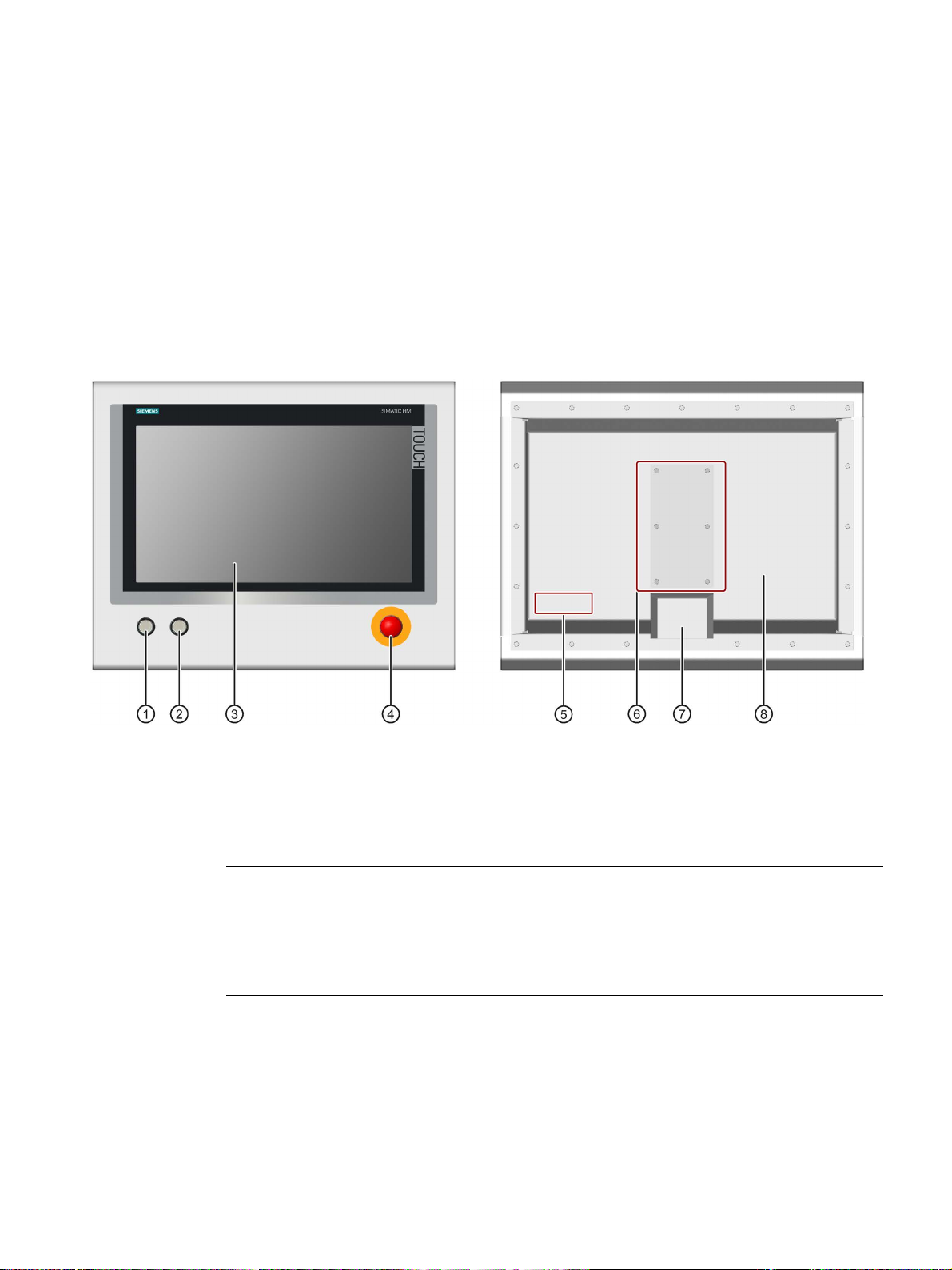
1
①
Illuminated pushbutton 1 "left" with green LED
⑤
Position of nameplate and approvals
②
Illuminated pushbutton 1 "right" with red LED
⑥
Connection compartment
③
Display with touch screen
⑦
Mechanical interface for fastening
④
EMERGENCY OFF button 1
⑧
Rear panel
Note
EMERGENCY OFF button
The connections of the EMERGENCY OFF button are wired to pins
in the connection compartment.
The EMERGENCY OFF button is not connected with the electronics inside the device.
The IFP1900 INOX PRO devices are mounted to a support arm or stand by means of the
mechanical interface. The IFP1900 INOX PRO devices are not intended for installation in a
control cabinet.
The figures below show the front view and rear view using a device with operator controls
and stand mounting as an example.
1
Only for devices with operator controls
IFP1900 INOX PRO
Compact Operating Instructions, 07/2019, A5E35751632-AC
1-4 of the terminal strip
5

Product description
•
INOX stainless steel, material number 1.4301
•
FPM (fluorinated rubber)
•
Polyester
•
IP66 all
•
2 illuminated pushbuttons, 1 EMERGENCY OFF button, wired to
internal terminal strip 1
•
For stand mounting, analogous for support arm mounting
Note
Accessories are intended only for the INOX devices listed above and not in general for other
PRO devices (standard).
Features
Properties of the IFP1900 INOX PRO:
Enclosure material:
Scope of delivery
Accessories
Sealing material:
Front membrane:
Degree of protection:
-based
-round
Front operator controls:
Mechanical interface:
1
Internal plug-in terminal strip only for devices with operator controls, pin assignment of the
internal terminal strip, see section "Pin assignment of the internal terminal strip (Page 31)"
● 1 x IFP1900 INOX PRO
● 1 x 2-pin connecting terminal for the 24 V DC power supply
● 1 x 20-pin connecting terminal, matching the internal 20-pin terminal strip of the device
● 1 x seal for mechanical interface
Mounting kit for stand mounting
A mounting kit is available for pedestal mounting of the device. Mounting kit contents:
● 1 stainless steel tube with flange: Length 500 mm, outer diameter 48.3 mm, inner
diameter 40 mm.
The mechanical interface of the stainless steel tube with flange fits the mechanical
interface of the device.
● 4 hexagon screws M5×25 made of stainless steel
● 1 flat seal
Article number 6AV7675-1GB00-0AA0
IFP1900 INOX PRO
6 Compact Operating Instructions, 07/2019, A5E35751632-AC

Product description
Mounting kit for support arm mounting
A mounting kit is available for support arm mounting of the device. Mounting kit contents:
● 1 stainless steel tube with flange: Length 500 mm, outer diameter 48.3 mm, inner
diameter 40 mm.
The mechanical interface of the stainless steel tube with flange fits the mechanical
interface of the device.
● 1 adapter support arm
● 8 hexagon screws M5×20 made of stainless steel
● 2 flat seals
Article number 6AV7675-1GB10-0AA0
Service pack
The service pack contains:
● 1 spare seal for the connection compartment cover of the device
● 6 screws for the connection compartment cover of the device
● 1 spare seal for the mechanical interface of the device
● 4 screws for fastening the stainless steel tube with flange from a mounting kit to the
mechanical interface of the device
● 1 connecting terminal for the power supply
● 1 terminal block for the terminal strip in the connection compartment
● Documentation
Article number 6AV7675-1JD20-0AA0
Service pack 2, only in combination with the service manual
The service pack 2 contains:
● 1 spare seal for the rear panel of the device
● 4 spare screws for the rear panel of the device
● 1 spare seal for the mechanical interface of the device
● 4 screws for fastening the stainless steel tube with flange from a mounting kit to the
mechanical interface of the device
● 1 connecting terminal for the power supply
● Documentation
Article number 6AV7675-1JD21-0AA0
IFP1900 INOX PRO
Compact Operating Instructions, 07/2019, A5E35751632-AC
7
Product description
WARNING
Opening the device and working on the opened device may only be carried out by qualified
and correspondingly trained personnel
Service pack 3, in connection with devices for support arm mounting
Service pack 3 contains:
● 1 spare seal for the connection compartment cover of the device
● 1 spare seal for the mechanical interface of the device
● 1 spare seal for support arm mounting
● 8 screws M5 x 20 mm for support arm mounting
● 6 screws for the connection compartment cover of the device
● 1 connecting terminal for the power supply
● 1 terminal block for the terminal strip in the connection compartment
● Documentation
Article number 6AV7675-1JD20-1AA0
Service manual
A service manual that describes the following maintenance work is available for the IFP1900
INOX PRO:
● Replacing the seal of the rear panel
● Replacing defective operator controls in the device front
● Converting a device for stand mounting into a device for support arm mounting and vice
versa
The service manual describes, amongst other points, the opening of the device and
working on the wiring or on electronic components in the inside of the device. Injuries or
material damage may result if the work is not carried out correctly.
The work described in the service manual may only be carried out by qualified specialist
personnel who have been trained correspondingly by Siemens.
The service manual is available online under "Product Support" next to this document in the
same branch of the product tree.
IFP1900 INOX PRO
8 Compact Operating Instructions, 07/2019, A5E35751632-AC
2
WARNING
Improper use can endanger safety.
WARNING
Performing a function test when installing the device in machines or systems
2.1 Intended use
The IFP1900 INOX PRO touch screen front panel devices are designed to be used for highperformance visualization tasks (operator control and monitoring) and in ambient conditions
such as those found in the food, beverage and pharmaceutical industries.
Improper use of the device endangers safety and can result in personal injury or damage to
property.
Any use deviating from the intended use is not permitted.
Operate the device only in accordance with its intended use.
Also see the information in the section "Cleaning the device (Page 20)".
Particular attention has been paid during design of the HMI devices to ensure that the front
panel is easy to clean and can be disinfected when needed. The devices with stainless steel
front have therefore been developed according to DIN EN 1672-2 "Food Processing
Machinery - Safety and Hygiene Requirements".
2.2 General safety instructions
Following the results of a risk analysis, additional protection equipment on the machine or
the system is necessary to avoid endangering persons. In particular, the programming,
parameter assignment and wiring of the inserted I/O must be executed in accordance with
the safety performance identified by the necessary risk analysis (SIL, PL or Cat.). The
intended use of the device has to be ensured.
The proper use of the device has to be verified with a function test on the system. These
tests help you to identify programming, parameter assignment and wiring errors. The test
results have to be recorded and, if necessary, entered into the safety verification
documents.
IFP1900 INOX PRO
Compact Operating Instructions, 07/2019, A5E35751632-AC
9
Safety instructions
WARNING
Risk of explosion, personal injury or material damage in the case of a defective touch
screen
2.2 General safety instructions
Defective touch screen
The application of excessive force to the device front can destroy the device touch screen,
for example, piercing the front membrane or breaking the touch screen carrier plate. There
is a risk of explosion, injury and food contamination with additional consequential and
health damage.
Make sure that excessive force cannot be applied to the device front.
If the device touch screen is defective, decommission the affected machine immediately
and replace the device at once. When replacing the device, please note the chapter
"Repair (Page 24)".
ESD
Electrostatically sensitive components include almost all electrical, electronic, optoelectronic
and electromechanical components. These components are sensitive to overvoltage for
technical reasons and their function may be impaired or destroyed by electrostatic discharge.
Observe the regulations governing the handling of ESD components.
Industrial Security
Siemens provides products and solutions with industrial security functions that support the
secure operation of plants, systems, machines and networks.
In order to protect plants, systems, machines and networks against cyber threats, it is
necessary to implement – and continuously maintain – a holistic, state-of-the-art industrial
security concept. Siemens’ products and solutions constitute one element of such a concept.
Customers are responsible for preventing unauthorized access to their plants, systems,
machines and networks. Such systems, machines and components should only be
connected to an enterprise network or the internet if and to the extent such a connection is
necessary and only when appropriate security measures (e.g. firewalls and/or network
segmentation) are in place.
For additional information on industrial security measures that may be implemented, please
visit (http://www.siemens.com/industrialsecurity).
Siemens’ products and solutions undergo continuous development to make them more
secure. Siemens strongly recommends that product updates are applied as soon as they are
available and that the latest product versions are used. Use of product versions that are no
longer supported, and failure to apply latest updates may increase customer’s exposure to
cyber threats.
To stay informed about product updates, subscribe to the Siemens Industrial Security RSS
Feed under (http://www.siemens.com/industrialsecurity).
IFP1900 INOX PRO
10 Compact Operating Instructions, 07/2019, A5E35751632-AC

Safety instructions
CAUTION
Safety-relevant mechanisms not visible or operable
NOTICE
HMI device approved for indoor use only
Note
Operate the device only in a normal atmospheric environment
The technical characteristics of the device described in the operating instructions are
guaranteed if you operate the device in normal ambient air conditions with usual air
composition.
2.3 Notes about usage
Disclaimer for third-party software updates
This product includes third-party software. Siemens AG only provides a warranty for
updates/patches of the third-party software, if these have been distributed as part of a
Siemens software update service contract or officially released by Siemens AG. Otherwise,
updates/patches are undertaken at your own risk. You can find more information about our
Software Update Service offer on the Internet at Software Update Service
(http://www.automation.siemens.com/mcms/automation-software/en/software-update-
service).
Notes on protecting administrator accounts
A user with administrator privileges has extensive access and manipulation options in the
system.
Therefore, ensure there are adequate safeguards for protecting the administrator accounts
to prevent unauthorized changes. To do this, use secure passwords and a standard user
account for normal operation. Other measures, such as the use of security policies, should
be applied as needed.
2.3 Notes about usage
Position the device in such a manner that safety-related mechanisms such as a mains
isolation switch remain visible, accessible and operable.
The HMI device may be damaged if operated outdoors.
Operate the HMI device indoors only ("Indoor use only").
IFP1900 INOX PRO
Compact Operating Instructions, 07/2019, A5E35751632-AC
11

3
3.1 Permitted mounting positions
The device may only be operated in landscape format with a maximum inclination of ±30° to
the vertical.
Permissible ambient temperature: 0 ... 45 °C
3.2 Mounting and connecting the device
This section describes how to mount and connect the device correctly, using stand mounting
as an example. Mounting on a support arm is carried out in the same way. All the work steps
in this chapter have to be carried out sequentially for complete mounting of the device.
Requirement
● A stand with a mechanical interface suitable for the mechanical interface of the device;
see section "Mechanical interface of the device (Page 28)".
● The following lines are routed through the stand:
– Protective conductor, minimum cross-section of 2.5 mm
– Lines for the external power supply, voltage-free
– Lines for the front operator controls
– All required data lines
● Four hexagon screws M5 according to screw standard ISO 4017, material X5CrNi18-10
2
The length of the screws have to be dimensioned so that the penetration depth of the
screw thread in the device-side flange lies in the range of 6 to 10 mm.
IFP1900 INOX PRO
12 Compact Operating Instructions, 07/2019, A5E35751632-AC

Installing the device
Note
The device is fastened to a stand or a support arm via the mechanical interface with four
screws.
Siemens AG assumes no liability for the consequences of a faulty installation.
WARNING
The device must be mounted securely
NOTICE
Placing the device on its front can damage operator controls
3.2 Mounting and connecting the device
Opening the connection compartment and installing the device
Inadequately dimensioned fastening material may cause the device to fall down. Serious
bodily injury may result.
Make sure that fasteners are adequately dimensioned during installation of the device.
Make sure to consider the weight of the device and the forces acting on the device when
dimensioning the fasteners. This applies in particular to dynamic load of the device.
Observe any further statutory specifications applying at the location of use of the device
and further applicable regulations with regard to the fastening of the device.
If you place the device on its front before or during the installation, the operator controls on
the front can be damaged.
Place the device on a soft and elevated surface so that the front operator controls do not
contact the working area and are not damaged.
IFP1900 INOX PRO
Compact Operating Instructions, 07/2019, A5E35751632-AC
13

Installing the device
3.2 Mounting and connecting the device
Procedure
1. Open the connection compartment. To do so, remove the 6 screws on the device rear
that are marked in the following figure and remove the connection compartment cover
and associated seal.
2. Place the supplied seal for the mechanical interface with its smooth side onto the stand.
Center the openings of the seal and of the mechanical interface of the stand.
3. Route the lines from the stand through the opening of the mechanical interface of the
device into the connection compartment.
4. Place the mechanical interface of the device onto the mechanical interface of the stand.
Take the following into account:
– The seal has to lie exactly in the mechanical interface of the device.
– The lines must not be squeezed. Hold the lines slightly tensioned while placing the
device on the stand.
5. Fasten the device to the mechanical interface of the stand using the four M5 screws.
Insert the screws from below through the mechanical interface and tighten the screws
with a torque of 3.5 Nm. The degree of protection IP66 is only ensured with this torque.
The device is mounted on the stand. The following steps describe the installation in the
connection compartment.
IFP1900 INOX PRO
14 Compact Operating Instructions, 07/2019, A5E35751632-AC

Installing the device
①
Connection for the 24 V DC power supply
⑤ USB 2.0 interfaces, high current
②
Ethernet interface
⑥ USB type B interface
③
Reset button
⑦ Connection for protective conductor
④
(only for devices with operator controls)
Note
Use copper cables on connectors with terminal connections
Use copper (Cu) cables for all supply lines that are connected to the
e.g. 24
Note
External interface cable
Lay external interface cables only indoors or up to a maximum length of 42.6
3.2 Mounting and connecting the device
The following figure shows the position of the interfaces.
Connecting cables
Use only shielded standard cables as data connecting cables, order information is available
on the Internet Industry Mall (https://mall.industry.siemens.com).
DisplayPort interface ⑧ Internal terminal strip, 20-pin
device with terminals,
V DC power supply cables on the 24 V DC power supply connector.
m outdoors.
IFP1900 INOX PRO
Compact Operating Instructions, 07/2019, A5E35751632-AC
15

Installing the device
WARNING
Electric shock and fire hazard when protective conductor is not connected
WARNING
Risk of fire and electric shock
NOTICE
Safe electrical isolation
3.2 Mounting and connecting the device
Connecting the device and closing the connection compartment
Important notes on connecting
The protective conductor connection is needed to protect the device and helps ensure that
interference signals generated by power lines, signal lines or lines to I/O devices are safely
discharged to earth.
The protective conductor connection on the device must be connected to the protective
conductor of the control cabinet or system in which the device is installed.
High voltage may be present in a defective device, which can cause fire or an electric
shock if touched. Death and serious bodily injury can result.
• Connect the device to the protective conductor before you put it into operation.
• Never operate the device without protective conductor.
• If a device is defective, remove it from operation without delay and label it accordingly.
Risk of electric shock if the device is opened incorrectly or defective. There is also a risk of
fire if the device or connecting lines are damaged.
You should therefore protect the device as follows:
• Always pull out the power plug when you are not using the device or if the device is
defective. The power plug must be freely accessible.
• Connect the device to a protective conductor as instructed (see "Connecting the
protective conductor").
• Use a central isolating switch in the case of cabinet installation.
The device may only be connected to a 24 V DC power supply that meets the requirements
of a safe extra-low voltage (SELV) according to IEC/EN/DIN EN/UL 60950-1 or the
requirements of a secure extra-low voltage (SELV/PELV) according to IEC 61131-2.
The power supply must meet the requirements of NEC Class 2 or LPS according to
IEC/EN/DIN EN/UL 60950‑1.
The supplying source must be fused for a power rating < 240 VA;
recommended fuse rating ≤ 8 A.
IFP1900 INOX PRO
16 Compact Operating Instructions, 07/2019, A5E35751632-AC

Installing the device
3.2 Mounting and connecting the device
Procedure
1. Connect the protective conductor to the protective conductor connection ⑥. The
protective conductor connection is identified by the following symbol:
The following applies for devices with a protective earth symbol: The branch circuit which
the protective conductor connection is connected to must be protected with a Branch
Circuit Protective Device of 20 A.
The minimum cross-section of the protective conductor is 2.5 mm
2
.
The protective conductor connection is needed to protect the device and helps ensure
that interference signals generated by power lines, signal lines or lines to I/O devices are
safely discharged to earth.
2. Connect the lines for the power supply via the associated connecting terminal to the
connection for the power supply
①.
Pin assignment: 1=24 V DC, 2=Ground
3. Connect the connectors of the data lines to the corresponding interface.
4. Secure the data lines with cable ties to the fastening elements in the connection
compartment that are marked in the following figure.
5. Place the seal of the connection compartment cover around the connection compartment.
Ensure that the latches of the seal lie in the associated notches and that the seal lies
flush on the device rear panel.
6. Fasten the connection compartment cover with 6 screws. Tighten the screws using a
torque of 3.5 Nm.
IFP1900 INOX PRO
Compact Operating Instructions, 07/2019, A5E35751632-AC
17

Installing the device
3.3 Dismantling the device
3.3 Dismantling the device
The device is generally removed in the reverse order for mounting and connecting.
Procedure
1. Close all open programs on the PC which is connected to the device.
2. Switch off power to the device.
3. When you use the device in a hazardous area, make sure that one of the two following
requirements is met:
i. The area is no longer hazardous.
ii. The device and its plug-in connections are de-energized.
4. Open the connection compartment by removing its cover.
5. If attached, remove all cable ties that were installed for tension relief of the connecting
cables in the connection compartment.
6. Remove all plug-in connectors and the equipotential bonding cable.
7. Remove the device from the support arm or pedestal. Make sure that the connection
cables are not damaged.
8. Fasten the connection compartment cover with 6 screws on the device, torque 3.5 Nm.
IFP1900 INOX PRO
18 Compact Operating Instructions, 07/2019, A5E35751632-AC

4
Note
Requirement
If you operate the device exclusively as monitor and do not change the brightness, you do
not need to commission the device. To use advanced functions of the device, perform the
following commissioning.
● The device is mounted according to the Quick Install Guide.
● The device is connected according to the Quick Install Guide.
The supplied connecting cables are only intended for commissioning and not for
continuous operation.
Procedure
● DVD "Documentation and Drivers" or USB stick with a copy of the DVD
1. Switch on the IPC.
2. Switch on the power supply of the IFP1900 INOX PRO.
3. Insert the "Documentation and Drivers" DVD into the CD/DVD drive of the IPC.
Alternatively, insert the USB stick with the copy of the DVD into a USB port on the device.
4. Follow the instructions for installation.
IFP1900 INOX PRO
Compact Operating Instructions, 07/2019, A5E35751632-AC
19

5
CAUTION
Unwanted reactions when cleaning the device
NOTICE
Damage to the device due to impermissible cleaning agents
5.1 General information on maintenance and servicing
Observe the following when servicing and repairing protective equipment e.g. such as
ground circuits or overvoltage protection components:
● Observe the maintenance and replacement intervals.
● Replace system components, including external cables, fuses and batteries only with
equivalent components approved by the respective manufacturer.
5.2 Cleaning
5.2.1 Cleaning the device
Cleaning Agents
The device is designed for low-maintenance operation. However, it is still necessary to clean
the device regularly.
Clean the entire device thoroughly:
● Before commissioning
● As required, depending on the degree of contamination
● At regular intervals (according to an internal cleaning plan)
You risk unintentional actuation of operator controls if you clean the device while it is
switched on.
You may possibly trigger unwanted actions of the device or controller that are liable to
cause personal injury or damage to the machinery.
Always switch off the device before you clean it.
Impermissible and unsuitable cleaning agents can cause damage the device.
Use dish soap or foaming screen cleaner only as cleaning agents.
IFP1900 INOX PRO
20 Compact Operating Instructions, 07/2019, A5E35751632-AC
Do not use aggressive solvents or scouring powder.

Maintaining and repairing the device
Note
Cleaning methods
In addition to the specifications in this section, the following applies for cleaning the device:
Permitted
DIN
Not permitted
•
•
• You damage the operating front if you clean the device with high pressure equipment. Do
Note
Unintentional responses
When cleaning the touch screen, an unintentional response in the controller can be triggered
by touch
Always open the clean screen or switch off the device before you clean the touch screen
while the system is running.
Cannot be operated when the clean screen is active
When the clean screen is active, operations on the device are not
Wait for the period of the clean screen to lapse. Then you can operate the system again with
the device.
5.2 Cleaning
Procedure
1. Switch off the device.
2. Dampen the cleaning cloth.
3. Spray the cleaning agent on the cloth and not directly on the device.
4. Clean the device with the cleaning cloth.
: Cleaning with strong jet water under increased pressure in accordance with
EN 60529:2014-09, specifications on "IP66".
:
Do not clean the device using aggressive cleaners or detergents, greasing or abrasive
detergents, acids or caustic solutions, leather, scratching or rough rags and equipment.
You can find additional information in the section "Chemical resistance (Page 22)".
Do not clean the device with chlorine or chloride, for example, active chlorine, with laser
or ultrasonic equipment, or with dry ice.
not clean the device thermally, for example, using hot steam equipment, because this
would inevitably damage the operating front and, in particular, the touch sensor system.
5.2.2 Clean screen
If you use the WinCC RT Advanced software in connection with the device, you can clean
the touch screen of the device while it is switched on and the project running. An operating
element must be available in the project that can be used to call the "clean" screen. Once
the clean screen is activated, touch screen operation is locked for a configured period of
time. The time the touch screen is locked can be set between 5 and 30 seconds. The time
remaining for the lockout is indicated by a progress bar.
IFP1900 INOX PRO
Compact Operating Instructions, 07/2019, A5E35751632-AC
ing keys.
possible.
21

Maintaining and repairing the device
5.2 Cleaning
5.2.3 Chemical Resistance
Front membrane
The resistance of the front membrane to various chemicals has been tested to DIN 42 115,
section 2. The front membrane is resistant to the chemicals listed below:
● Alcohol
● Diluted acids
● Diluted caustic solutions
● Ester
● Hydrocarbons
● Household cleaners
You can find information of chemical resistance on the Internet.
Seals
The seals made of FPM (fluorinated rubber) are approved for food according to FDA
CFR21.177.2600 for use with dry, watery and fatty foods.
5.2.4 Working with stainless steel surfaces
Resistance
Information on the resistance of stainless steel:
● The stainless steel surface is not fully resistant against the chemicals listed below:
– Hydrochloric acid
– Sulphuric acid
– Sodium hydroxide
– Chlorine
– Chlorides
Do not clean the stainless steel surface with these chemicals or with similar acids or
caustic solutions.
● Acid steam develops, for example, when tiles are cleaned with hydrochloric acid, and is
also harmful to the stainless steel. If the stainless steel parts are unintentionally
contaminated with hydrochloric acid, rinse these off immediately with plenty of water.
● Clean the stainless steel surface with a cleansing agent without active chlorine.
IFP1900 INOX PRO
22 Compact Operating Instructions, 07/2019, A5E35751632-AC

Maintaining and repairing the device
5.2 Cleaning
Cleaning guidelines
Further information on stainless steel surfaces:
● The surface should be properly ventilated.
● Keep the surface clean. Remove cleaners and food residue immediately. Always avoid
the return of food stuff splashes to the production process.
● If mechanical cleaning is necessary, do not use cleaning equipment made of metal.
– Use brushes made of plastic or natural materials, or a microfiber pad.
– Use plenty of water to clean the surface.
– Make sure that the cleansing agent is completely removed without any residue.
● Make sure surface is not damaged: Do not damage the device during operation, or by
cleaning or repairing it using hard tools, in particular tools made of corrodible materials.
● Make sure that the surface does not come into contact with rusted parts.
This includes water pipes, filings, residue from wire brushes or steel wool. These, as well
as rust films have a corrosive effect on parts made of stainless steel.
– Remove any stains or rust immediately.
– Remove new rust spots with a mild abrasive detergent in order to prevent any further
corrosion.
– Rinse the part thoroughly after you cleaned it.
IFP1900 INOX PRO
Compact Operating Instructions, 07/2019, A5E35751632-AC
23

Maintaining and repairing the device
5.3 Resetting the device to factory settings
5.3 Resetting the device to factory settings
The reset button is used to reset the device to factory settings, for example, when the
IFP1900 INOX PRO can no longer communicate with the IPC for a longer period.
During the reset to factory settings, the IP address of the IFP1900 INOX PRO, for example,
is reset to the default value "192.168.1.2".
Procedure
1. Switch off the device's power supply.
2. Press the reset button with a suitable tool and keep the reset button pressed.
3. Switch on the device's power supply and keep the reset button pressed for an additional
10 seconds.
During this the two LAN LEDs are deactivated briefly.
5.4 Repair
In case of repair, the device must be shipped to the Return Center in Erlangen. Repairs may
only be carried out at the Return Center in Erlangen.
The device described in this document is covered by the conditions of repair and return of
equipment, as follows:
1. You return the defective device to the returned goods center. The address is:
Siemens AG
Digital Factory Retouren-Center
c/o Geis Service GmbH, Tor 1-4
Kraftwerkstraße 25a
91056 Erlangen
Germany
2. After it has been repaired, the device is returned to you. A new device will not be supplied
in exchange.
Depending on the work necessary to repair the device, the Center may decide to give you a
credit note. In this case, it is your responsibility to order a new device.
For additional information, refer to the Internet at Spare parts and repairs
(http://support.automation.siemens.com/WW/view/en/16611927).
IFP1900 INOX PRO
24 Compact Operating Instructions, 07/2019, A5E35751632-AC

6
Note
This section lists the certificates and approvals possible for the
Only those approvals specified on the rear of your device apply to your device.
6.1 Certificates and approvals
A copy of the certificates can be requested from the following address:
Siemens AG
Digital Factory
Factory Automation
DF FA SE R&D
Breslauer Str. 5
DE-90766 Fürth
device.
DIN ISO 9001 certificate
The Siemens quality management system for all production processes (development,
production and sales) meets the requirements of DIN ISO 9001:2000.
This has been certified by DQS (the German society for the certification of quality
management systems).
Certificate registration no. DE-000656 QM08
Software license agreements
If the device is supplied with preinstalled software, you must observe the corresponding
license agreements.
UL approval
Underwriters Laboratories Inc. (UL) in accordance with
● UL508 (Industrial Control Equipment) and
● CSA C22.2 No.142 (Process Control Equipment)
IFP1900 INOX PRO
Compact Operating Instructions, 07/2019, A5E35751632-AC
25

Specifications
Field of application
Requirement for emissions
Requirement for interference immunity
Industrial area
EN 61000-6-4:2007 +A1:2011
EN 61000-6-2:2005
6.2 Guidelines and declarations
ATEX/IECEx approval
Special conditions of use
The SIMATIC Industrial Flat Panel with article number 6AV7484-6AB..-0AA0 including the
top side of the stand provides a degree of protection of at least IP66. The bottom side of the
stand shall be connected to a certified enclosure, providing a degree of protection of at least
IP54 according to IEC 60079-15 for gas and non-conductive dust and IP6X according to IEC
60079-31, for conductive dust, taking into account the environmental conditions under which
the equipment is used.
The equipment shall be installed in such a way that the risk of mechanical danger is low.
To avoid an electrostatic charge, wipe the enclosure surface with a damp cloth only.
When used in an area requiring the use of equipment with EPL Gc:
● The equipment shall only be used in an area of not more than pollution degree 2, as
defined in EN 60664-1.
● Provisions shall be made to prevent the rated voltage from being exceeded by transient
disturbances of more than 119 V.
Under the special conditions mentioned, the following approvals apply to the device:
● II 3 G Ex nA IIC T4 Gc and
II 3 D Ex tc IIIC T70 ºC Dc
ATEX certificate number: DEKRA 16ATEX0045X
Standards: EN 60079-0:2012 +A11:2013, EN 60079-15:2010, EN 6007931:2014
● Ex nA IIC T4 Gc and
Ex tc IIIC T70 ºC Dc
IECEx certificate number: DEK 16.0021X
Standards: IEC 60079-0:2011 (Ed.6), +Corr.1. 2012 +Corr.2. 2013, IEC 60079-15:2010
(Ed. 4), IEC 60079-31:2013 (Ed. 2)
6.2 Guidelines and declarations
Notes on CE marking
This product meets the requirements and safety objectives of the EMC directive 2014/30/EU
(EMC Directive), and is designed for operation in the following fields of application according
to this CE marking:
IFP1900 INOX PRO
26 Compact Operating Instructions, 07/2019, A5E35751632-AC

Specifications
6.3 Dimension drawings
6.3 Dimension drawings
6.3.1 IFP1900 INOX PRO
The figures below show the dimension drawings using a device with operator controls and
stand mounting as an example.
IFP1900 INOX PRO
Compact Operating Instructions, 07/2019, A5E35751632-AC
27

Specifications
Weight
Approx. 15 kg
Quality assurance
In accordance with ISO 9001
IFP1900 INOX PRO
Permitted voltage range
+19.2 V to +28.8 V
Rated current
2.0 A
Inrush current I2t
0.5 A2s
Power consumption 2
40 W
Maximum permitted transients
35 V (500 ms)
Minimum time between two transients
50 s
Internal protection
Electronic
1
2
The power loss generally corresponds to the specified value for power consumption.
6.4 Technical specifications
6.3.2 Mechanical interface of the device
6.4 Technical specifications
6.4.1 General technical specifications
DC power supply
Rated voltage 1
The generation of the supply voltage with the line-side power supply must be realized as safety
extra-low voltage with safe electrical isolation, isolated as SELV according to
IEC/UL/EN/DIN-EN 60950-1.
24 V DC
IFP1900 INOX PRO
28 Compact Operating Instructions, 07/2019, A5E35751632-AC

Specifications
Emission standard
EN 61000-6-4; CISPR 22:2010 Class A; FCC Class A
± 2 kV in accordance with IEC 61000-4-5; asymmetrical surge
length > 30 m
± 8 kV air discharge in accordance with IEC 61000-4-2
10 V, 9 kHz to 80 MHz according to IEC 61000-4-6
Immunity to magnetic fields
100 A/m, 50/60 Hz according to IEC 61000-4-8
Display, resolution
19" diagonal with backlighting, resolution 1366 x 768 pixels
Touch force with test pen; 2 mm diameter: 5 N
Half brightness life time, typical
Min. 50000 h at 50 °C, 50% brightness
ISO 9241-307
USB
2 × USB 2.0, high current
10, 100, 1000 Mbps
Keyboard, mouse
Connection via USB interface
6.4 Technical specifications
Electromagnetic compatibility
Graphics
Immunity with regard to conducted
interference on the supply lines
Noise immunity on signal lines ± 2 kV in accordance with IEC 61000-4-4; burst; length > 3 m
Immunity to electrostatic discharge ± 6 kV contact discharge in accordance with IEC 61000-4-2
Immunity to RF interference 10 V/m, 80 to 2000 MHz
Touch controller Resistive Semtech controller ELO CTR-2216SU-AT-CHP-00
Backlighting (MTBF)
Pixel error class in accordance with
± 2 kV in accordance with IEC 61000-4-4; burst
± 1 kV in accordance with IEC 61000-4-5; symmetrical surge
± 2 kV in accordance with IEC 61000-4-5; symmetrical surge,
80% AM according to IEC 61000-4-3
3 V/m, 2 to 2.7 GHz
Touch screen analog resistive
LED
I
Interfaces
LAN interface X1 P1, RJ45 Intel distance connection via Gigabit Ethernet;
IFP1900 INOX PRO
Compact Operating Instructions, 07/2019, A5E35751632-AC
29

Specifications
Temperature, tested in accordance with IEC 60068-2-1, IEC 60068-2-2
Relative humidity, tested in accordance with IEC 60068-2-78, IEC 60068-2-30
Air pressure, in accordance with IEC 60068-2-13
Vibration, tested according to IEC 60068-2-6
58 to 500 Hz: 10 m/s2, 10 cycles
8.5 to 500 Hz: 10 m/s2
Shock resistance, tested in accordance with IEC 60068-2-27, IEC 60068-2-29
Degree of protection
Explanation
6.4 Technical specifications
6.4.2 Environmental conditions
Climatic ambient conditions
• Temperature gradient in operation
• Ambient temperature in operation
• Temperature during storage/transport
• Storage/transport, gradient
• Operation
• Storage/transport
• Operation
• Storage/transport
Mechanical ambient conditions
• Operation
• Storage/transport
Max. 10 °C/h, no condensation
0 to 45 °C
-20 to +60 °C
Max. 20 °C/h, no condensation
5 to 85% at 30 °C, no condensation
5 to 95% at 25/55 °C, no condensation
1140 to 795 hPa, corresponds to an elevation of -1000 to 2000 m
1140 to 660 hPa, corresponds to an elevation of -1000 to 3500 m
10 to 58 Hz: 0.15 mm
5 to 8.5 Hz: 7 mm
• Operation
• Storage/transport
150 m/s2, 11 ms, 100 shocks per axis
250 m/s2, 6 ms, 1000 shocks per axis
Protection against foreign objects and water
The device meets the requirements according to IEC 60529 and UL50.
All-round When mounted:
• IP66 according to IEC 60529
• Enclosure Type 4X (indoor use only) according to UL50
The degrees of protection can only be guaranteed if the seals are completely flush at the
mechanical interfaces and the associated covers are closed.
The IP66 degree of protection is not covered by the UL approval and was not tested as part
of the UL approval.
Degree of pollution / overvoltage category according to IEC 61131
● Degree of pollution 2
● Overvoltage category II
IFP1900 INOX PRO
30 Compact Operating Instructions, 07/2019, A5E35751632-AC

Specifications
6.5 Description of the interfaces
6.5 Description of the interfaces
6.5.1 Pin assignment of the internal terminal strip
This section applies to devices with operator controls.
The figure below shows the pin assignment of the internal 20-pin terminal strip.
● Pins 1 to 12 are wired with the front operator controls.
● Pins 13 to 20 are not assigned.
IFP1900 INOX PRO
Compact Operating Instructions, 07/2019, A5E35751632-AC
31

A
A.1 Service and support
You can find additional information and support for the products described on the Internet at
the following addresses:
● Technical support (https://support.industry.siemens.com)
● Support request form (http://www.siemens.com/automation/support-request)
● After Sales Information System SIMATIC IPC/PG (http://www.siemens.com/asis)
● SIMATIC Documentation Collection (http://www.siemens.com/simatic-tech-doku-portal)
● Your local representative
(http://www.automation.siemens.com/mcms/aspa-db/en/Pages/default.aspx)
● Training center (http://sitrain.automation.siemens.com/sitrainworld/?AppLang=en)
● Industry Mall (https://mall.industry.siemens.com)
When contacting your local representative or Technical Support, please have the following
information at hand:
● MLFB of the device
● BIOS version for industrial PC or image version of the device
● Other installed hardware
● Other installed software
Tools & downloads
Please check regularly if updates and hotfixes are available for download to your device. The
download area is available on the Internet at the following link:
After Sales Information System SIMATIC IPC/PG (http://www.siemens.com/asis)
IFP1900 INOX PRO
32 Compact Operating Instructions, 07/2019, A5E35751632-AC
 Loading...