

Page 1

___________________
___________________
___________________
___________________
___________________
___________________
___________________
___________________
___________________
___________________
SIMATIC NET
Industrial Ethernet / PROFIBUS
IE/PB LINK PN IO
Operating Instructions
11/2017
C79000
Preface
Application and properties
1
LEDs, connectors, buttons
2
Installation, connecting up,
commissioning
3
Configuration and operation
4
Diagnostics and
maintenance
5
Technical data
6
Approvals
7
Accessories
A
Documentation references
B
-G8976-C393-02
Page 2

Siemens AG
Division Process Indust ries and Drives
Postf ach 48 48
90026 NÜRNBERG
GERMANY
C79000-G8976-C393-02
Ⓟ
Copyright © Siemens AG 2016 - 2017.
All rights res erved
Legal information
Warning notice system
DANGER
indicates that death or severe personal injury will result if proper precautions are not taken.
WARNING
indicates that death or severe personal injury may result if proper precautions are not taken.
CAUTION
indicates that minor personal injury can result if proper precautions are not taken.
NOTICE
indicates that property damage can result if proper precautions are not taken.
Qualified Personnel
personnel qualified
Proper use of Siemens products
WARNING
Siemens products may only be used for the applications described in the catalog and in the relevant technical
Trademarks
Disclaimer of Liability
This manual contains notices you have to observe in order to ensure your personal safety, as well as to prevent
damage to property. The notices referring to your personal safety are highlighted in the manual by a safety alert
symbol, notices referring only to property damage have no safety alert symbol. These notices shown below are
graded according to the degree of danger.
If more than one degree of danger is present, the warning notice representing the highest degree of danger will
be used. A notice warning of injury to persons with a safety alert symbol may also include a warning relating to
property damage.
The product/system described in this documentation may be operated only by
task in accordance with the relevant documentation, in particular its warning notices and safety instructions.
Qualified personnel are those who, based on their training and experience, are capable of identifying risks and
avoiding potential hazards when working with these products/systems.
Note the following:
documentation. If products and components from other manufacturers are used, these must be recommended
or approved by Siemens. Proper transport, storage, installation, assembly, commissioning, operation and
maintenance are required to ensure that the products operate safely and without any problems. The permissible
ambient conditions must be complied with. The information in the relevant documentation must be observed.
All names identified by ® are registered trademarks of Siemens AG. The remaining trademarks in this publication
may be trademarks whose use by third parties for their own purposes could violate the rights of the owner.
We have reviewed the contents of this publication to ensure consistency with the hardware and software
described. Since variance cannot be precluded entirely, we cannot guarantee full consistency. However, the
information in this publication is reviewed regularly and any necessary corrections are included in subsequent
editions.
for the specific
11/2017 Subject to change
Page 3
Preface
Validity of this manual
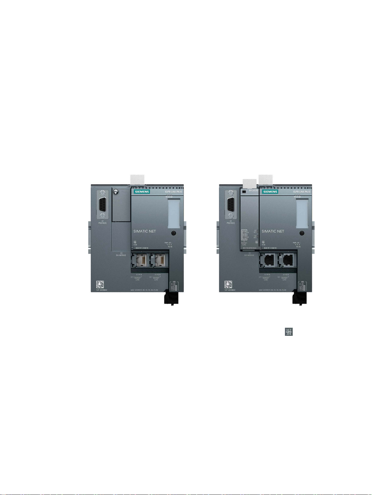
IE/PB LINK PN IO without bus adapter
IE/PB LINK PN IO with bus adapter
This document contains information on the following product:
IE/PB LINK PN IO
Article Article number 6GK1 411-5AB10
Hardware product version 1
Firmware version V3.0
Link between Industrial Ethernet and PROFIBUS with PROFINET IO functionality
On the front of the housing, you will see the firmware version and the hardware product
version printed as a placeholder "X". If the printed text is, for example, "
placeholder for hardware product version 1.
IE/PB LINK PN IO
Operating Instructions, 11/2017, C79000-G8976-C393-02
", X is the
3
Page 4

Preface
Product names and abbreviations
Purpose of the manual
Cross references
New in this release
Replaced edition
Current manual release on the Internet
● LINK
In this document, the name "LINK" is used in place of the full product name
"IE/PB LINK PN IO".
● STEP 7
The short form of the configuration tool is used for the following products:
– STEP 7 V5.x
– STEP 7 Professional
The short form "STEP 7" is used only when the product is self explanatory in the context.
● PST
Primary Setup Tool
As an alternative to STEP 7, you can use the PST to configure the address and
PROFINET parameters.
This manual describes the properties of this module and supports you when installing and
commissioning it.
The required configuration steps are described as an overview and there are explanations of
the relationship between firmware functions and configuration.
You will also find information about the diagnostics options of the device.
In this manual there are often cross references to other sections.
To be able to return to the initial page after jumping to a cross reference, some PDF readers
support the command <Alt>+<Left arrow>.
● Editorial revision
● New LED description
● Changes in the operating behavior of the C-PLUG
Edition 11/2016
You will also find the current version of this manual on the following Internet page of
Siemens Industry Online Support:
IE/PB LINK PN IO
4 Operating Instructions, 11/2017, C79000-G8976-C393-02
Page 5

Preface
Requirements for use of the module
Innovations and compatibility with the previous version (6GK1 411-5AB00)
Note
Make sure that you read the information relating to enhanced functions and restrictions in the
section
Required experience
Sources of information and other documentation
License conditions
Note
Open source software
The product contains open source software. Read the license conditions for open source
software carefully before using the product.
Security information
Link: (https://support.industry.siemens.com/cs/ww/en/ps/15406/man)
You will find the requirements for using the module in the section Requirements for use
(Page 19).
You will find the functions of the module in the section Communication services and other
properties (Page 15).
Replacing a module (Page 73).
To install, commission and operate the LINK, you require experience in the following areas:
● Automation engineering
● STEP 7 V5.x / STEP 7 Professional
You will find an overview of further reading and references in the Appendix Documentation
references (Page 89).
You will find license conditions in the following document on the supplied data medium:
● OSS_IEPB-LINK_86.pdf
Siemens provides products and solutions with industrial security functions that support the
secure operation of plants, systems, machines and networks.
IE/PB LINK PN IO
Operating Instructions, 11/2017, C79000-G8976-C393-02
5
Page 6

Preface
Firmware
SIMATIC NET glossary
In order to protect plants, systems, machines and networks against cyber threats, it is
necessary to implement – and continuously maintain – a holistic, state-of-the-art industrial
security concept. Siemens’ products and solutions only form one element of such a concept.
Customer is responsible to prevent unauthorized access to its plants, systems, machines
and networks. Systems, machines and components should only be connected to the
enterprise network or the internet if and to the extent necessary and with appropriate security
measures (e.g. use of firewalls and network segmentation) in place.
Additionally, Siemens’ guidance on appropriate security measures should be taken into
account. For more information about industrial security, please visit
Link: (http://www.siemens.com/industrialsecurity)
Siemens’ products and solutions undergo continuous development to make them more
secure. Siemens strongly recommends to apply product updates as soon as available and to
always use the latest product versions. Use of product versions that are no longer supported,
and failure to apply latest updates may increase customer’s exposure to cyber threats.
To stay informed about product updates, subscribe to the Siemens Industrial Security RSS
Feed under
Link: (http://www.siemens.com/industrialsecurity).
The firmware is signed and encrypted. This ensures that only firmware created by Siemens
can be downloaded to the device.
Explanations of many of the specialist terms used in this documentation can be found in the
SIMATIC NET glossary.
You will find the SIMATIC NET glossary here:
● SIMATIC NET Manual Collection or product DVD
The DVD ships with certain SIMATIC NET products.
● On the Internet under the following address:
Link: (https://support.industry.siemens.com/cs/ww/en/view/50305045)
IE/PB LINK PN IO
6 Operating Instructions, 11/2017, C79000-G8976-C393-02
Page 7

Table of contents
Preface ................................................................................................................................... 3
1 Application and properties .........................................................................................................11
2 LEDs, connectors, buttons ........................................................................................................21
3 Installation, connecting up, commissioning ..................................................................................31
4 Configuration and operation ......................................................................................................45
1.1 Application, modes and operating modes........................................................................... 11
1.2 Communication services and other properties.................................................................... 15
1.3 Performance data .............................................................................................................. 17
1.3.1 Characteristics of S7 communication ................................................................................. 17
1.3.2 Characteristics of data record routing................................................................................. 17
1.3.3 Total number of connections .............................................................................................. 18
1.3.4 Characteristic data for PROFINET IO ................................................................................ 18
1.3.5 Characteristic data of the C-PLUG ..................................................................................... 18
1.3.6 Update time for parallel operation of PROFINET IO with other services ............................. 19
1.4 Requirements for use ........................................................................................................ 19
2.1 LED displays of the LINK ................................................................................................... 21
2.2 LED displays of the bus adapter ........................................................................................ 25
2.3 Interfaces, bus adapters, buttons ....................................................................................... 26
2.4 X80: External power supply ............................................................................................... 27
2.5 Maintenance mode ............................................................................................................ 28
3.1 Important notes on using the device .................................................................................. 31
3.1.1 Notices on use in hazardous areas .................................................................................... 31
3.1.2 Notes on use in hazardous areas according to ATEX / IECEx ............................................ 33
3.1.3 Notices regarding use in hazardous areas according to UL HazLoc ................................... 33
3.1.4 Notes on use in hazardous areas according to FM ............................................................. 34
3.2 Overview: Installation, configuration, commissioning .......................................................... 35
3.3 Installing and connecting up the LINK ................................................................................ 36
3.4 PG/PC connector .............................................................................................................. 37
3.5 C-PLUG ............................................................................................................................ 38
3.6 Commissioning and startup of the LINK ............................................................................. 42
3.7 Changing from RUN to STOP ............................................................................................ 44
4.1 Security recommendations ................................................................................................ 45
4.2 IP configuration ................................................................................................................. 47
4.2.1 Configuring the IP address ................................................................................................ 47
4.2.2 Restart after detection of a duplicate IP address in the network.......................................... 48
IE/PB LINK PN IO
Operating Instructions, 11/2017, C79000-G8976-C393-02
7
Page 8

Table of contents
5 Diagnostics and maintenance ................................................................................................... 69
6 Technical data........................................................................................................................ 77
4.2.3 Remove retentive storage of the IP address if there are duplicate addresses ......................48
4.3 Assign the address and network parameters with the Primary Setup Tool (PST) .................48
4.4 Configuration with STEP 7 V5.5 .........................................................................................51
4.4.1 Configuring the LINK ..........................................................................................................51
4.4.2 Use as PROFINET IO device and as gateway ....................................................................52
4.4.3 Commissioning the LINK as a PROFINET IO device ..........................................................53
4.4.4 Use only as a gateway in standard operation ......................................................................53
4.4.4.1 Creating a station and networking the LINK ........................................................................53
4.4.4.2 Setting object properties on the LINK..................................................................................54
4.4.4.3 Configuring the Ethernet interface ......................................................................................55
4.4.4.4 Configuring the PROFIBUS interface ..................................................................................55
4.4.4.5 Commissioning the LINK as a gateway ...............................................................................55
4.4.5 Configuring bus adapters....................................................................................................56
4.5 Configuration with STEP 7 Basic / Professional ..................................................................57
4.5.1 Configuring the LINK ..........................................................................................................57
4.5.2 Use as a PROFINET IO device ..........................................................................................57
4.5.3 Use only as a gateway in standard operation ......................................................................59
4.5.4 Configuring bus adapters....................................................................................................59
4.5.5 Commissioning the LINK as a PROFINET IO device ..........................................................60
4.5.6 Commissioning the LINK in standard mode ........................................................................61
4.6 Identification and maintenance data ...................................................................................61
4.6.1 Reading out and entering I&M data ....................................................................................61
4.6.2 Data record structure for I&M data ......................................................................................64
4.7 Time-of-day synchronization ...............................................................................................65
4.8 Overview: Access to the LINK as proxy ..............................................................................67
5.1 Diagnostics options ............................................................................................................69
5.2 Clearing and for resetting to factory settings .......................................................................70
5.3 Loading firmware ................................................................................................................71
5.4 Upload tp PG/Upload from device.......................................................................................73
5.5 Replacing a module ............................................................................................................73
5.5.1 Resetting address data.......................................................................................................73
5.5.2 Replacing older modules ....................................................................................................73
5.5.3 Replacing a module without PG/PC ....................................................................................74
5.6 SNMP ................................................................................................................................75
6.1 Technical specifications of the LINK ...................................................................................77
6.2 Pinout of the Ethernet interface ..........................................................................................79
6.3 Pin assignment of the PROFIBUS interface ........................................................................79
IE/PB LINK PN IO
8 Operating Instructions, 11/2017, C79000-G8976-C393-02
Page 9

Table of contents
7 Approvals...............................................................................................................................81
A Accessories ............................................................................................................................85
B Documentation references ........................................................................................................89
Index .....................................................................................................................................91
A.1 BusAdapter ....................................................................................................................... 85
A.2 C-PLUGs........................................................................................................................... 86
B.1 /1/...................................................................................................................................... 89
B.2 /2/...................................................................................................................................... 90
B.3 /3/...................................................................................................................................... 90
B.4 /4/...................................................................................................................................... 90
B.5 /5/...................................................................................................................................... 90
IE/PB LINK PN IO
Operating Instructions, 11/2017, C79000-G8976-C393-02
9
Page 10

Table of contents
IE/PB LINK PN IO
10 Operating Instructions, 11/2017, C79000-G8976-C393-02
Page 11

1
1.1
Application, modes and operating modes
Basic function
Modes
PROFINET IO proxy
Standard mode (gateway)
Note
Changing the mode with Clear/Reset
If you want to change the configured mode of the LINK, you need to clear/reset the LINK.
Note that this deletes the configuration data, see also the
to factory settings
The LINK is a gateway that connects the two network types Industrial Ethernet and
PROFIBUS.
The LINK allows access to all PROFIBUS nodes connected to the underlying PROFIBUS
network.
The LINK has the design of the SIMATIC ET 200SP device family.
You can use the LINK in the following modes:
●
●
You specify the mode in the configuration. For the "PROFINET IO proxy" mode, you need to
configure the LINK as a PROFINET IO device. This procedure is described in the section
Configuration and operation (Page 45).
section Clearing and for resetting
(Page 70).
IE/PB LINK PN IO
Operating Instructions, 11/2017, C79000-G8976-C393-02
11
Page 12
Application and properties
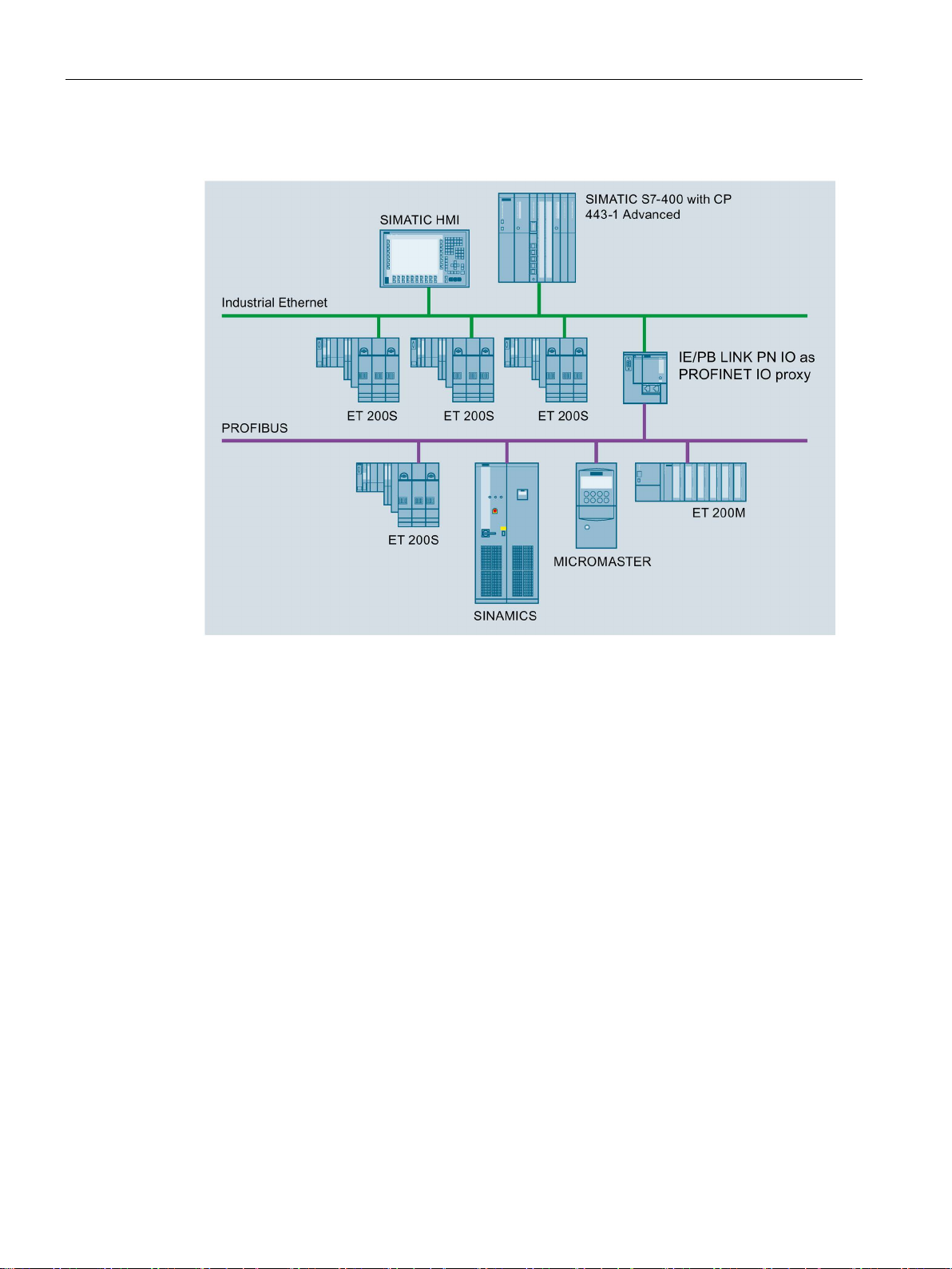
Gateway as PROFINET IO proxy
1.1 Application, modes and operating modes
Figure 1-1 IE/PB LINK PN IO as PROFINET IO proxy
The LINK provides the connection between a PROFINET IO controller on Industrial Ethernet
and PROFIBUS slaves visible as PROFINET IO devices via the LINK.
From the perspective of the PROFINET IO controller there is no difference between
accessing PROFINET IO devices on Industrial Ethernet and DP slaves on PROFIBUS.
The LINK adopts the role of a proxy for the DP slaves connected to PROFIBUS.
As a PROFINET IO proxy, the LINK supports among other things the following functions:
● PG/OP communication, e.g. for loading programs and configuration data.
● Data record routing, among other things, for configuring field devices, for example with
SIMATIC PDM.
● Gateway to a DP master system
● S7 routing
IE/PB LINK PN IO
12 Operating Instructions, 11/2017, C79000-G8976-C393-02
Page 13
Application and properties
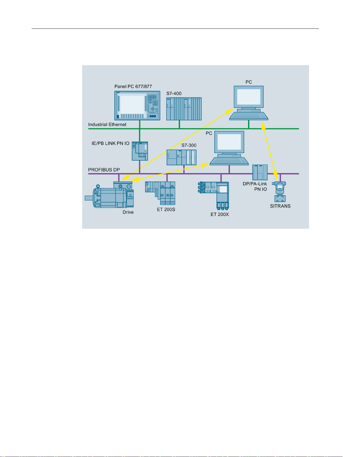
Gateway in standard operation
1.1 Application, modes and operating modes
Figure 1-2 IE/PB LINK PN IO as gateway in standard operation
In standard operation, the LINK supports the following functions:
● PG/OP communication, e.g. for loading programs and configuration data.
● Data record routing, among other things, for configuring field devices, for example with
SIMATIC PDM.
● Gateway to a DP master system
● S7 routing
You will find further details about the functions in the below.
IE/PB LINK PN IO
Operating Instructions, 11/2017, C79000-G8976-C393-02
13
Page 14

Application and properties
Operating modes
Normal mode
Maintenance mode
Maintenance mode
Maintenance mode after startup
Maintenance mode by pressing the button
1.1 Application, modes and operating modes
The LINK has two operating modes:
●
This is the mode that the LINK adopts during normal operation both in PROFINET IO
proxy and in standard mode.
●
Functions that can only be executed in maintenance mode:
– Firmware download
– Restart
– Resetting to factory settings
Access to the three functions of the maintenance mode depends on how the LINK is set to
the maintenance mode.
●
After startup the LINK is in maintenance mode for 10 seconds and then changes
automatically to normal mode. In this status only the following function can be executed:
– Loading firmware
●
After pressing the button the LINK is in maintenance mode for 10 minutes. The following
functions are possible:
– Restart
– Resetting to factory settings
To change from normal mode to maintenance mode using the button, refer to the section
Maintenance mode (Page 28).
IE/PB LINK PN IO
14 Operating Instructions, 11/2017, C79000-G8976-C393-02
Page 15

Application and properties
1.2
Communication services and other properties
Communication services
Industrial Ethernet
PROFINET IO
IP configuration - IPv4
Media redundancy (MRP)
SNMP
LLDP
PROFIBUS
Supported slaves:
Direct data exchange
PROFISAFE
1.2 Communication services and other properties
●
The LINK can be configured as an IO device.
●
The essential features of IP configuration for the LINK:
– The LINK supports IP addresses according to IPv4.
– Address assignment:
The IP address, the subnet mask and the address of a gateway can be set manually
in the configuration.
As an alternative, the IP address can be obtained from a DHCP server or by other
means outside the configuration.
●
Within an Ethernet network with a ring topology, the LINK supports the media redundancy
protocol MRP. You can assign the role of "Client" to the LINK.
●
As an SNMP agent, the LINK supports data queries using SNMP (Simple Network
Management Protocol).
For more detailed information, refer to section SNMP (Page 75).
●
The LINK supports the Link Layer Discovery Protocol.
●
– Slaves according to DP V0
– Slaves according to DP V1
●
The LINK supports direct data exchange in its own DP Master system and in multimaster
systems.
●
The LINK supports applications with PROFISAFE.
IE/PB LINK PN IO
Operating Instructions, 11/2017, C79000-G8976-C393-02
15
Page 16

Application and properties
Gateway to a DP master system
Data record gateway
Other services and properties
MPI networking (only in standard operation)
PG/OP communication
S7 routing
Time synchronization
Firmware update
C-PLUG as exchangeable storage medium for configuration data
1.2 Communication services and other properties
●
The LINK serves as a gateway between Ethernet and PROFIBUS. The LINK is operated
as an active node on a PROFIBUS network.
●
Field device parameter assignment (data record routing)
You can use the LINK as a router for data records intended for PROFIBUS nodes.
Devices that are not directly attached to PROFIBUS and that therefore do not have direct
access to the PROFIBUS nodes can transfer data records to the field devices via the
LINK, e.g. via SIMATIC PDM (Process Device Manager).
●
The LINK can be selected as a gateway in standard operation between an MPI subnet
and an Ethernet subnet.
To do this, you need to network the PROFIBUS interface of the LINK with the MPI
subnet.
●
– Loading programs and configuration data
– Running test and diagnostics functions
– Operator control and monitoring (HMI systems) of a system.
●
Cross-subnet S7 connections, for example for HMI operation.
The LINK forwards communication via S7 connections. This service is used, for example,
by HMI applications (PC stations).
●
The LINK supports time synchronization using the following methods:
– SIMATIC mode
– NTP
The LINK uses the synchronized time-of-day, for example for forwarding and time
stamping diagnostics buffer entries.
●
The LINK supports firmware updates using the firmware loader. A firmware file can be
loaded from a PC/PG via PROFIBUS, see section Loading firmware (Page 71).
●
The LINK supports storage of configuration data on the optional exchangeable storage
medium C-PLUG. This simplifies replacement of a defective module by simply inserting
the C-PLUG in the new module.
IE/PB LINK PN IO
16 Operating Instructions, 11/2017, C79000-G8976-C393-02
Page 17

Application and properties
Independent of media
Redundant power supply
1.3
Performance data
1.3.1
Characteristics of S7 communication
Characteristic
Explanation / values
connections are used.
1.3.2
Characteristics of data record routing
Field device parameter assignment (data record routing)
Characteristic
Explanation / values
PROFIBUS nodes
PROFIBUS nodes via a connection
1.3 Performance data
●
The LINK supports the connection of bus adapter modules of the ET 200SP device
family, for example for connecting to optical networks.
●
The LINK can be connected to a redundant power supply.
Table 1- 1 Number of connections for S7 communication
Maximum number of S7 connections / HMI connections
32
For the S7 communication both configured and unconfigured S7
You can use the LINK as a router for data records intended for field devices (PROFIBUS
nodes):
Devices that are not connected directly to PROFIBUS and therefore have no direct access to
the field devices can send data records to the field devices for example via the LINK using
the SIMATIC PDM (Process Device Manager).
The function is enabled as default.
Maximum number of connections to the
Maximum data record size for parameters sent to
32
244 bytes
IE/PB LINK PN IO
Operating Instructions, 11/2017, C79000-G8976-C393-02
17
Page 18

Application and properties
1.3.3
Total number of connections
Characteristic
Explanation / values
Note
Note that for every S7 connection used a TCP/IP connection is occupied on industrial
Ethernet.
1.3.4
Characteristic data for PROFINET IO
Characteristic
Explanation / values
(PROFINET IO devices)
Maximum number of DP inputs
2048 bytes
1.3.5
Characteristic data of the C-PLUG
Usable C-PLUGs
C-PLUG 32
C-PLUG 256
1.3 Performance data
Maximum number of:
• S7 connections
• HMI connections
• Data record routing connections
In total 48 in any combination
Table 1- 2 Number of connections for PROFINET IO
Maximum number of DP slaves assigned to the
LINK (DP Master).
64
Maximum number of DP outputs 2048 bytes
The LINK can be operated with the following C-PLUGs:
●
Memory:
– Total capacity: 32 MB
– Free capacity available: 30 MB
●
Memory:
– Total capacity: 256 MB
– Free capacity available: 126 MB
IE/PB LINK PN IO
18 Operating Instructions, 11/2017, C79000-G8976-C393-02
Page 19

Application and properties
1.3.6
Update time for parallel operation of PROFINET IO with other services
Configuring a higher update time
Note
Do not set the shortest possible update time
In parallel operation do not set the shortest possible update time but select the next higher
value proposed by STEP 7.
1.4
Requirements for use
Configuration and downloading
1.4 Requirements for use
Recommendation: Avoid writing data cyclically. The flash area allows a limited number of
write cycles.
You will find details in the section C-PLUGs (Page 86).
Dependent on the number of PROFINET IO devices operated in the same Ethernet subnet:
STEP 7 automatically sets the lowest possible value for the update time for the IO devices.
When necessary configure the update time for the IO devices via the properties of the
PROFINET interface in STEP 7:
● STEP 7 V5.x
"IO Cycle"
● STEP 7 Basic / Professional
"Advanced options" > "Real time settings"
In the following cases, configure a higher update time:
● Alongside the cyclic communication via PROFINET IO, you use non-cyclic
communications services, e.g. S7 connections, data record routing, HMI connections.
● Diagnostics or alarm frames occur often in the DP Master system.
You can configure the LINK for all modes via Industrial Ethernet. If you use the device as a
gateway in standard operation, it is also possible to download the configuration data via
PROFIBUS.
IE/PB LINK PN IO
Operating Instructions, 11/2017, C79000-G8976-C393-02
19
Page 20

Application and properties
STEP 7 versions
STEP 7 versions
Function
The functionality of firmware version V1.0 can be used.
Downloading the support package / HSP from the Internet
Installation of Hardware Support Packages
Primary Setup Tool (PST)
1.4 Requirements for use
Below you will find the STEP 7 products required to configure the LINK. If both STEP 7 V5.x
as well as STEP 7 Basic / Professional are named, one of the two products can be used as
an alternative.
STEP 7 V5.3 SP1 LINK with article number 6GK1 411-5AB00
• STEP 7 V5.3 + SP2 + Hotfix 1 + HSP 1007
• STEP 7 Basic / Professional V11
• STEP 7 V5.5 + SP4 + Hotfix 11 + HSP 1101
• STEP 7 Basic / Professional V14 + Update
1 + Support package 0192
LINK with article number 6GK1 411-5AB00
The functionality of firmware version V2.x can be used.
LINK with article number 6GK1 411-5AB10
The functionality of firmware version V3.0 can be used.
You will find the HSP or support package on the following Internet pages of Siemens
Industry Support.
● STEP 7 V5.x
Link: (https://support.industry.siemens.com/cs/ww/en/view/23183356)
● STEP 7 Basic / Professional
Link: (https://support.industry.siemens.com/cs/ww/en/ps/14667/dl)
● STEP 7 V5.x
Install the HSP in STEP 7 / HW Config with the "Options" > "Install Hardware Updates"
menu command.
You will find information in the online help: Keyword "HSP" or "Hardware update").
After installing an HSP, you need to close and restart STEP 7.
● STEP 7 Basic / Professional
Install the support package in STEP 7 from the file system of the engineering station
using the menu command "Options" > "Support packages".
The information system of STEP 7 will provide you with information: Keyword "Support
packages".
Version V4.2.1 is required for configuration with the PST.
You can download the current version from the pages of Siemens Industry Support:
Link: (https://support.industry.siemens.com/cs/ww/en/view/19440762)
IE/PB LINK PN IO
20 Operating Instructions, 11/2017, C79000-G8976-C393-02
Page 21
2
2.1
LED displays of the LINK
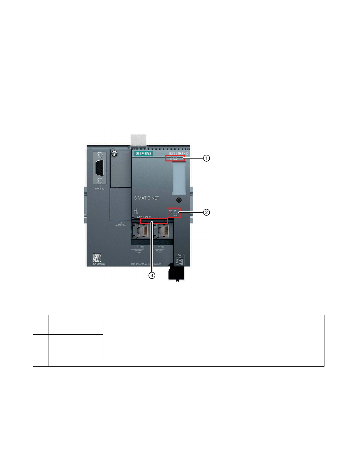
LEDs of the module
No.
LED
Meaning
①
②
(LK1 / LK2)
Figure 2-1 LEDs of the IE/PB LINK PN IO
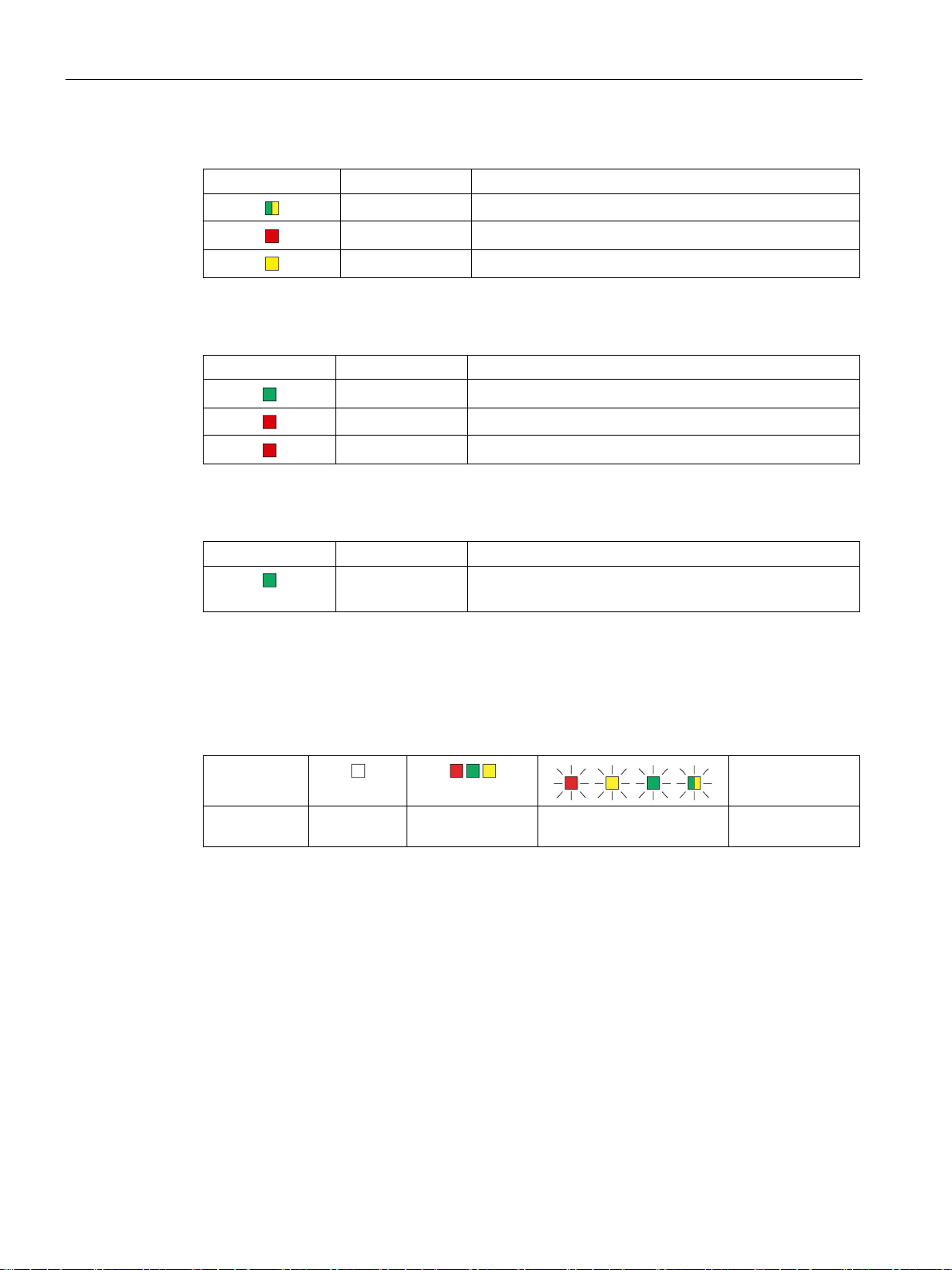
The module has the following LED groups for displaying the status:
Top LED strip The LEDs show the basic statuses, see table below,
Lower LED strip
Connection status
③
LEDs
IE/PB LINK PN IO
Operating Instructions, 11/2017, C79000-G8976-C393-02
Status of the connection to Ethernet / PROFINET
The LEDs of the Ethernet ports are lit only when no bus adapter is plugged in.
21
Page 22
LEDs, connectors, buttons
LEDs / colors
Name
Meaning
LEDs / colors
Name
Meaning
LED / color
Name
Meaning
(When using a TS a us adapter "LK1 / LK2" are disabled.)
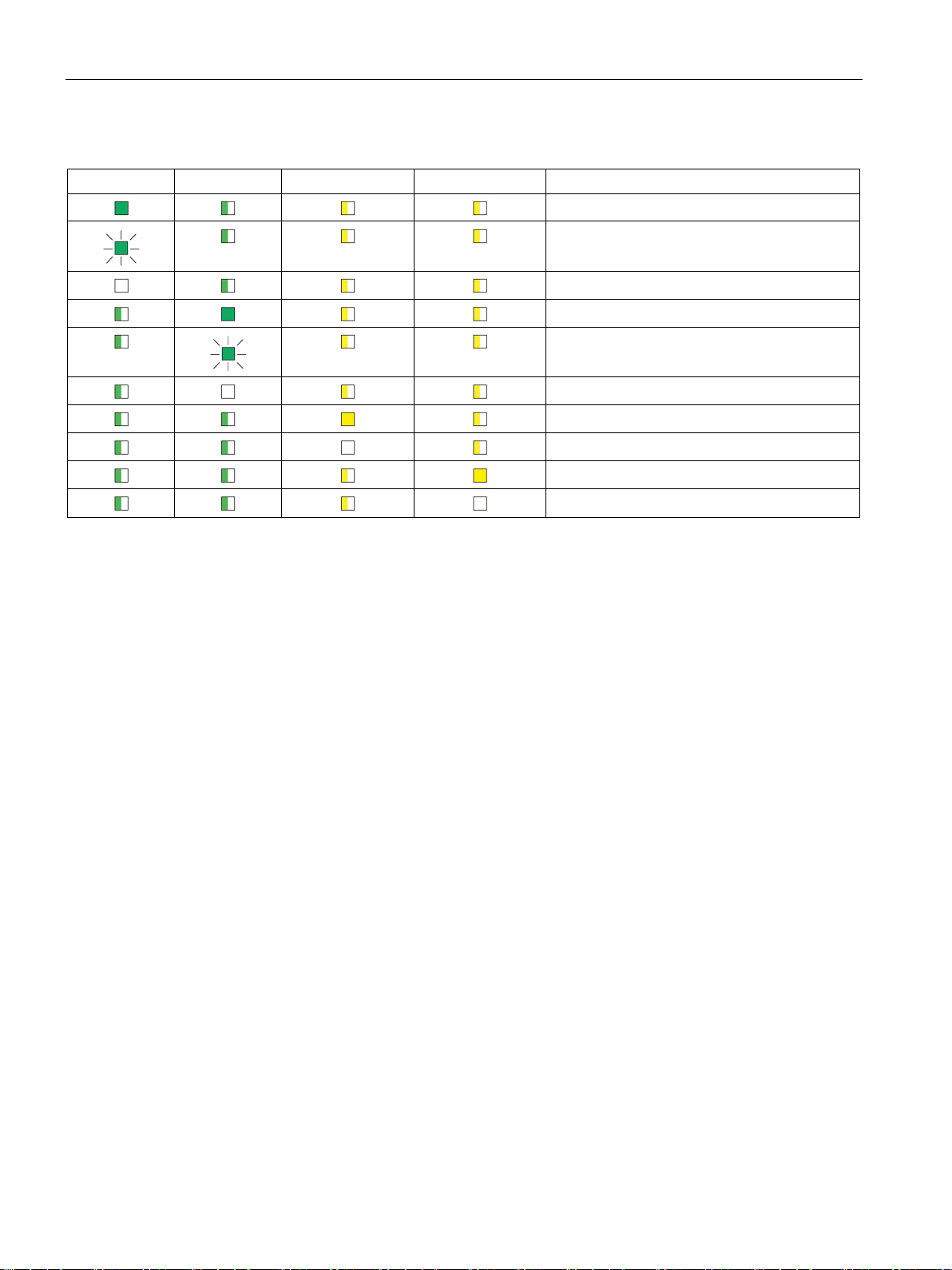
Display of the operating and communications statuses
Symbol
LED status
relevant
2.1 LED displays of the LINK
Table 2- 1 Top LED strip ① - basic statuses
R/S Operating status of the LINK (RUN/STOP)
ER Error
MT Maintenance
Table 2- 2 LED strip ② - basic statuses
PWR Power supply
BF PN PROFINET bus error
BF PB PROFIBUS bus error
Table 2- 3 LEDs of the Ethernet ports ③
LK1 / LK2 Status of the connection to Ethernet/PROFINET
The LED symbols in the following tables have the following significance:
Table 2- 4 Meaning of the LED symbols
OFF ON (steady light) Flashing LED status not
-
IE/PB LINK PN IO
22 Operating Instructions, 11/2017, C79000-G8976-C393-02
Page 23
LEDs, connectors, buttons
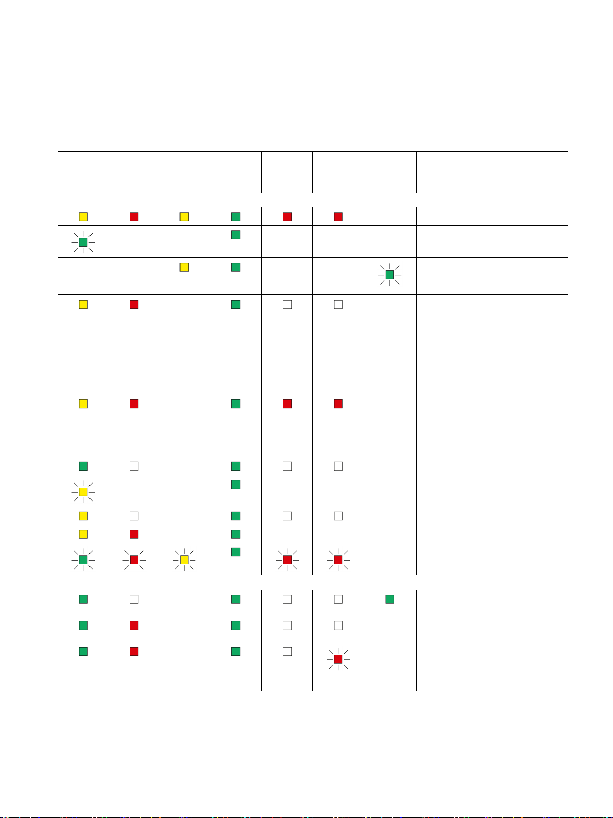
R/S
green)
ER
MT
PWR
BF PN
BF PB
LK1/LK2 *
Meaning
Startup, operating statuses, errors
ing startup)
-
-
-
Operating statuses, error (PROFIBUS and Ethernet)
tion at port, no data traffic
module (DP slave)
2.1 LED displays of the LINK
The LEDs indicate the operating and communications status of the module according to the
following scheme:
Table 2- 5 Display schemes for detailed module statuses
(yellow /
- -
(red)
- -
(yellow)
-
-
(green)
(red)
- - - Starting up (STOP → RUN)
- -
(red)
(green)
- Turn on (lamp test)
Finding modules on Ethernet
(LK1/LK2 flashes slowly, only dur-
-
-
- Running (RUN) without error
• Distribution of the PROFINET
configuration data during
startup
• Bus adapter configured but not
plugged in.
• Bus adapter plugged in but not
configured.
• Reset to factory settings
• Status following a memory
reset
• Device new and started up
- -
IE/PB LINK PN IO
Operating Instructions, 11/2017, C79000-G8976-C393-02
-
-
-
- - - Stopping (RUN → STOP)
- Stopped (STOP)
- - - Stopped (STOP) with error
- Module fault / system error
- Running (RUN), problem with a
- Running (RUN), module missing
Running (RUN), Ethernet connec-
on PROFIBUS or is incorrectly
configured (does not apply to
PROFINET IO).
23
Page 24
LEDs, connectors, buttons
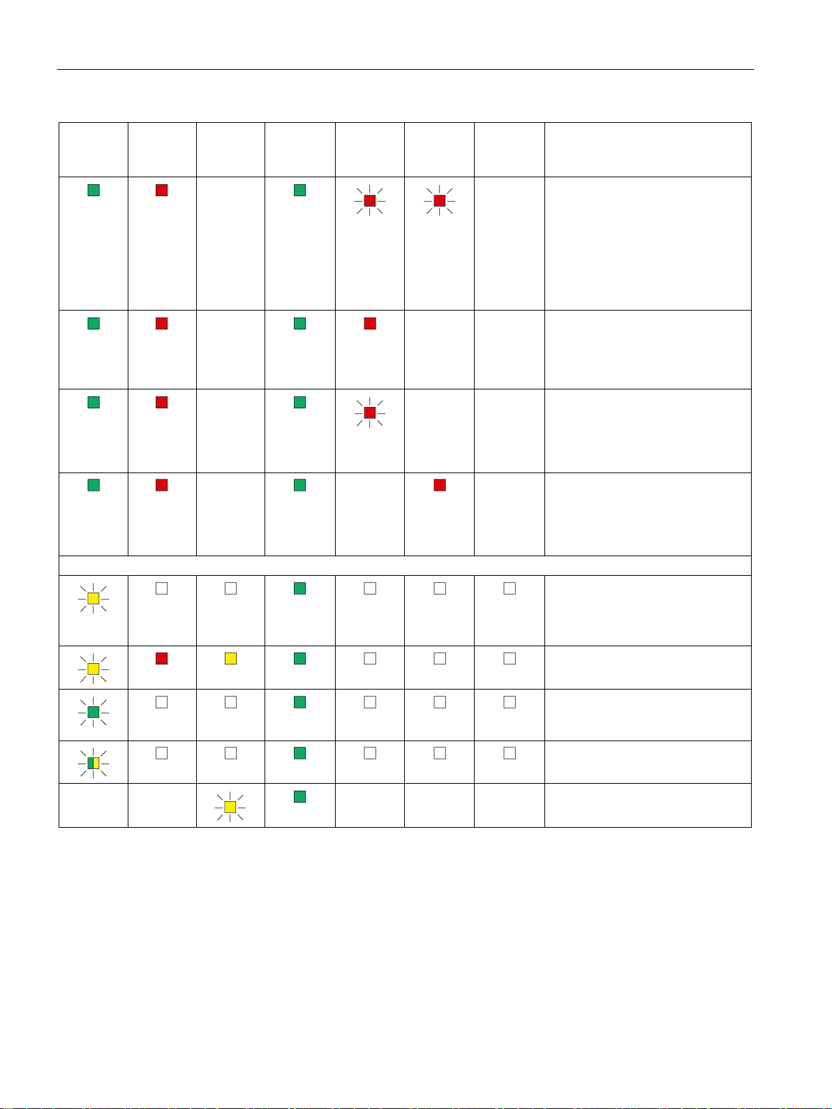
R/S
green)
ER
MT
PWR
BF PN
BF PB
LK1/LK2 *
Meaning
Maintenance mode Firmware download , Reset
firmware (Page 71).
after the restart.
2.1 LED displays of the LINK
(yellow /
(red)
(yellow)
-
-
-
-
(green)
(red)
-
(red)
- - Running (RUN) with error.
- - Running (RUN)
(green)
- Running (RUN) with error:
• Error on PROFIBUS that also
affects PROFINET IO (e.g. IO
device).
• Error on PROFINET IO that
also affects PROFIBUS (e.g.
proxy not put into operation).
• Error on PROFINET IO No
logical or physical connection
to the PROFINET IO controller.
• No module on PROFIBUS.
• At least one DP slave is disa-
bled (e.g. via SFC 12).
- Running (RUN)
• Problems on PROFIBUS
• No PROFIBUS configuration to
match system
- -
- - - Maintenance mode (after pressing
Maintenance mode (after startup)
Ready to load a firmware file via
PROFIBUS. See section Loading
Error loading firmware
Status after failed firmware update
When downloading firmware via
PROFIBUS: Firmware is loaded
Loaded firmware not activated.
the button)
IE/PB LINK PN IO
24 Operating Instructions, 11/2017, C79000-G8976-C393-02
Page 25
LEDs, connectors, buttons
R/S
green)
ER
MT
PWR
BF PN
BF PB
LK1/LK2 *
Meaning
*
The LEDs LK1/LK2 are also used for the node flash test.
Note
LEDs LK1/LK2 turned off when bus adapters are connected
If bus adapters are connected to the LINK for the Ethernet connection, the LEDs LK1/LK2 of
the LINK are turned off.
In this case, the LEDs of the bus adapter need to be evaluated, see section
the bus adapter
2.2
LED displays of the bus adapter
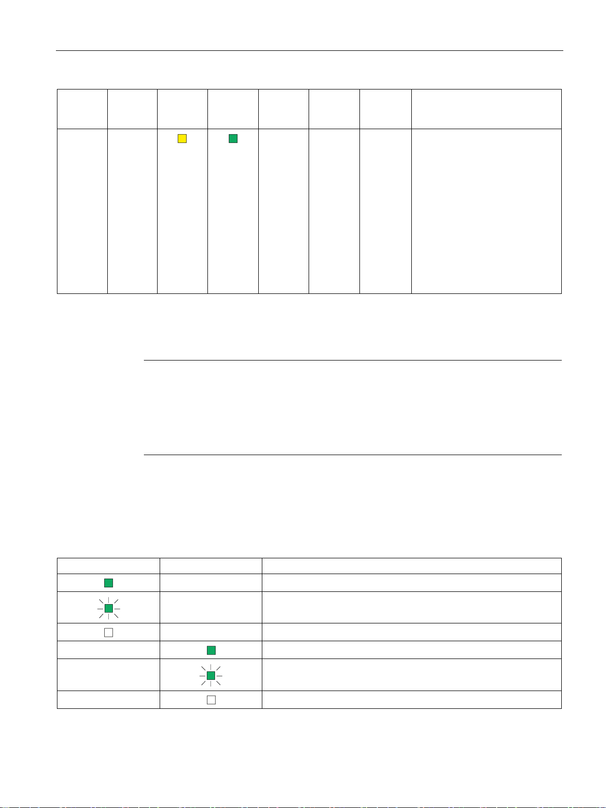
LK1
LK2
Meaning
2.2 LED displays of the bus adapter
(yellow /
- -
The LEDs LK1/LK2 flash very quickly when there is data traffic. When there is a high load. It may not be possible to dis-
tinguish the flashing from steady light.
(red)
(yellow)
(green)
(red)
- - - Maintenance demanded:
(red)
(green)
• Problem with redundant power
supply
• C-PLUG not detected or incor-
rectly formatted
• Program is adopted after re-
start,
(Note: After plugging in a CPLUG after a memory reset a
second restart is necessary.)
• Duplicate database (internal
memory and C-PLUG)
(Page 25).
Table 2- 6 Display scheme of the bus adapter "BA 2xRJ45"
- Ethernet connection at port 1, no data traffic
- Data traffic at port 1
- No Ethernet connection at port 1
-
-
-
LED displays of
Ethernet connection at port 2, no data traffic
Data traffic at port 2
No Ethernet connection at port 2
IE/PB LINK PN IO
Operating Instructions, 11/2017, C79000-G8976-C393-02
25
Page 26
LEDs, connectors, buttons
LK1
LK2
MT1
MT2
Meaning
2.3
Interfaces, bus adapters, buttons
Interfaces X1 and X2
Interface X3 for for bus adapter
2.3 Interfaces, bus adapters, buttons
Table 2- 7 Display scheme of the optical bus adapter "BA 2xSCRJ"
Ethernet connection at port 1, no data traffic
You will find the technical specifications and assignment of the Ethernet interface X1 and the
PROFIBUS interface X2 in the section Technical data (Page 77).
Data traffic at port 1
No Ethernet connection at port 1
Ethernet connection at port 2, no data traffic
Data traffic at port 2
No Ethernet connection at port 2
Maintenance demanded port 1
Port 1 without maintenance demand
Maintenance demanded port 2
Port 2 without maintenance demand
At the top right beside the PROFIBUS interface, there is the interface X3 for bus adapters of
the ET 200SP device family.
As an alternative, you can use this interface for connection to Ethernet if, for example, you
require an optical connection to the LINK.
The interface is constructed in the ET 200SP design and pin assignment.
You will find further information in the catalog, in Siemens Industry Mall and in the system
manual of the ET 200SP, see /4/ (Page 90) and in the appendix BusAdapter (Page 85).
For information on configuring the bus adapters in STEP 7 V5 refer to the section
Configuring bus adapters (Page 56).
IE/PB LINK PN IO
26 Operating Instructions, 11/2017, C79000-G8976-C393-02
Page 27

LEDs, connectors, buttons
Note
Deactivated Ethernet interface
When you plug in a bus adapter, the ports X1P1R
interface of the LINK are deactivated.
Button
WARNING
EXPLOSION HAZARD
2.4
X80: External power supply
External power supply
2.4 X80: External power supply
For information on configuring the bus adapters in STEP 7 Professional refer to the section
Configuring bus adapters (Page 59).
/ X1P2R of the integrated Ethernet
Do not press the button if there is a potentially explosive atmosphere.
The button serves the following purposes:
● Changeover to maintenance mode
● Restart
After the restart a new firmware file can be loaded, see section Loading firmware
(Page 71).
● Resetting to factory settings
For information on using the button and changing to the maintenance mode see the following
section.
The connector X80 (socket) for the external 24 VDC power supply is located on the bottom
of the LINK. The external power supply is redundant (optional use).
The power supply is connected to the LINK with the supplied 4-pin plug-in terminal block.
The plug-in terminal block is designed so that it can only be inserted in one position in the
X80 socket of the LINK.
The connector X80 has electronic reverse polarity protection.
IE/PB LINK PN IO
Operating Instructions, 11/2017, C79000-G8976-C393-02
27
Page 28
LEDs, connectors, buttons
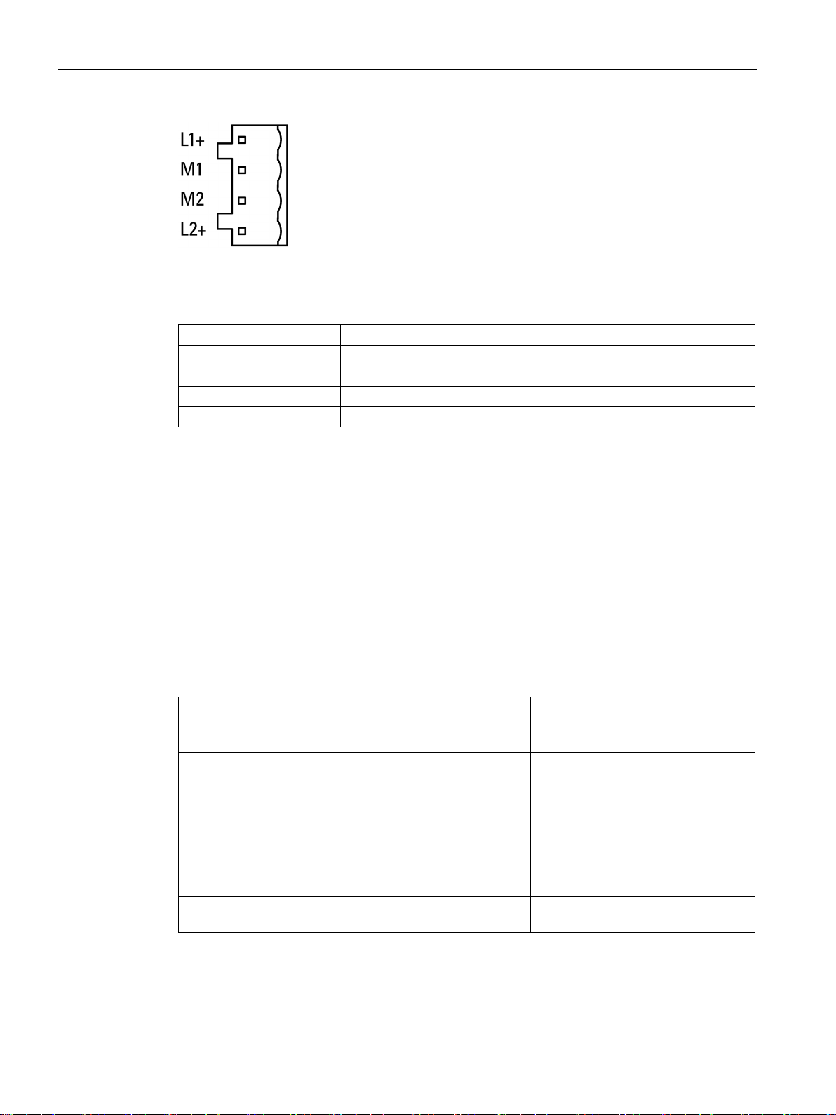
Labeling
Function
L1+
24 V DC
M2
Reference ground
L2+
24 VDC
2.5
Maintenance mode
Changing to the maintenance mode using the button
Operating mode
before pressing the
button
Pressing the button
Effect
minutes.
2.5 Maintenance mode
Figure 2-2 Redundant power supply
Table 2- 8 Pin assignment of the socket for the power supply
M1 Reference ground
For information on the connector, refer to the section "Installing and connecting up the LINK
(Page 36)".
You will find further data on the power supply in section Technical data (Page 77).
The functions of the maintenance mode are obtained as follows:
Table 2- 9 Functions of the maintenance mode
Normal mode Press the button for 3 seconds The LINK changes to maintenance
mode You can use the following functions:
• Restart
• Resetting to factory settings
Without any further actions, the LINK
returns to the normal mode after 5
IE/PB LINK PN IO
28 Operating Instructions, 11/2017, C79000-G8976-C393-02
Maintenance mode Press the button for 1 second The maintenance mode is extended
by 5 minutes.
Page 29

LEDs, connectors, buttons
Operating mode
before pressing the
button
Pressing the button
Effect
(Page 71).
settings (Page 70).
2.5 Maintenance mode
Maintenance mode Press the button twice briefly within 5
seconds
Maintenance mode Press the button for at least 10 sec-
onds
The LINK restarts.
Following this the LINK remains ready
for new firmware for 10 seconds, see
also section Loading firmware
The LINK is reset to the factory settings.
Note that configuration data is deleted
when you reset, refer to the section
Clearing and for resetting to factory
IE/PB LINK PN IO
Operating Instructions, 11/2017, C79000-G8976-C393-02
29
Page 30

LEDs, connectors, buttons
2.5 Maintenance mode
IE/PB LINK PN IO
30 Operating Instructions, 11/2017, C79000-G8976-C393-02
Page 31

3
3.1
Important notes on using the device
Safety notices on the use of the device
Overvoltage protection
NOTICE
Protection of the external power supply
coupling in of strong electromagnetic pulses onto the power supply cables is possible. This
The connector of the external power supply is not protected from strong electromagnetic
3.1.1
Notices on use in hazardous areas
WARNING
WARNING
EXPLOSION HAZARD
Note the following safety notices when setting up and operating the device and during all
associated work such as installation, connecting up or replacing the device.
If power is supplied to the module or station over longer power cables or networks, the
can be caused, for example by lightning strikes or switching of higher loads.
pulses. To protect it, an external overvoltage protection module is necessary. The
requirements of EN61000-4-5, surge immunity tests on power supply lines, are met only
when a suitable protective element is used. A suitable device is, for example, the Dehn
Blitzductor BVT AVD 24, article number 918 422 or a comparable protective element.
Manufacturer:
DEHN+SOEHNE GmbH+Co.KG Hans Dehn Str.1 Postfach 1640 D-92306 Neumarkt,
Germany
The device may only be operated in an environment with pollution degree 1 or 2 (see IEC
60664-1).
Do not press the button if there is a potentially explosive atmosphere.
IE/PB LINK PN IO
Operating Instructions, 11/2017, C79000-G8976-C393-02
31
Page 32

Installation, connecting up, commissioning
WARNING
EXPLOSION HAZARD
WARNING
must be connected to the power supply terminals. The power supply unit for the equipment
If the equipment is connected to a redundant power supply (two separate power supplies),
WARNING
EXPLOSION HAZARD
WARNING
EXPLOSION HAZARD
SUBSTITUTION OF COMPONENTS MAY IMPAIR SUITABILITY FOR CLASS I, DIVISION
WARNING
3.1 Important notes on using the device
DO NOT OPEN WHEN ENERGIZED.
The equipment is designed for operation with Safety Extra-Low Voltage (SELV) by a
Limited Power Source (LPS).
This means that only SELV / LPS complying with IEC 60950-1 / EN 60950-1 / VDE 0805-1
power supply must comply with NEC Class 2, as described by the National Electrical Code
(r) (ANSI / NFPA 70).
both must meet these requirements.
DO NOT CONNECT OR DISCONNECT EQUIPMENT WHEN A FLAMMABLE OR
COMBUSTIBLE ATMOSPHERE IS PRESENT.
2 OR ZONE 2.
When used in hazardous environments corresponding to Class I, Division 2 or Class I,
Zone 2, the device must be installed in a cabinet or a suitable enclosure.
IE/PB LINK PN IO
32 Operating Instructions, 11/2017, C79000-G8976-C393-02
Page 33

Installation, connecting up, commissioning
3.1.2
Notes on use in hazardous areas according to ATEX / IECEx
WARNING
Requirements for the cabinet/enclosure
WARNING
Cable
exceeds 80 °C, special precautions must be taken. If the equipment is operated in an air
, only use cables with admitted maximum operating temperature
WARNING
Take measures to prevent transient voltage surges of more than 40% of the rated voltage.
3.1.3
Notices regarding use in hazardous areas according to UL HazLoc
WARNING
EXPLOSION HAZARD
3.1 Important notes on using the device
To comply with EU Directive 94/9 (ATEX95), the enclosure or cabinet must meet the
requirements of at least IP54 in compliance with EN 60529.
If the cable or conduit entry point exceeds 70 °C or the branching point of conductors
ambient in excess of 50 °C
of at least 80 °C.
This is the case if you only operate devices with SELV (safety extra-low voltage).
DO NOT DISCONNECT WHILE CIRCUIT IS LIVE UNLESS AREA IS KNOWN TO BE
NON-HAZARDOUS.
This equipment is suitable for use in Class I, Division 2, Groups A, B, C and D or nonhazardous locations only.
This equipment is suitable for use in Class I, Zone 2, Group IIC or non-hazardous locations
only.
IE/PB LINK PN IO
Operating Instructions, 11/2017, C79000-G8976-C393-02
33
Page 34

Installation, connecting up, commissioning
3.1.4
Notes on use in hazardous areas according to FM
WARNING
EXPLOSION HAZARD
You may only connect or disconnect cables carrying electricity when the power supply is
WARNING
EXPLOSION HAZARD
temperature of the enclosure corresponds to the ambient temperature of the module. Use
3.1 Important notes on using the device
switched off or when the device is in an area without inflammable gas concentrations.
This equipment is suitable for use in Class I, Division 2, Groups A, B, C and D or nonhazardous locations only.
This equipment is suitable for use in Class I, Zone 2, Group IIC or non-hazardous locations
only.
The equipment is intended to be installed within an ultimate enclosure. The inner service
installation wiring connections with admitted maximum operating temperature of at least
30 ºC higher than maximum ambient temperature.
IE/PB LINK PN IO
34 Operating Instructions, 11/2017, C79000-G8976-C393-02
Page 35

Installation, connecting up, commissioning
3.2
Overview: Installation, configuration, commissioning
3.2 Overview: Installation, configuration, commissioning
Follow the steps as shown below. Installation and configuration can be performed
independently of each other.
Figure 3-1 Installing, connecting up and configuring the LINK
IE/PB LINK PN IO
Operating Instructions, 11/2017, C79000-G8976-C393-02
35
Page 36

Installation, connecting up, commissioning
3.3
Installing and connecting up the LINK
①
X2: PROFIBUS interface: 1 x 9-pin D-sub female connector
②
X3: Interface for ET 200SP bus adapter (behind the labeling plate)
③
X50: Receptacle for C-PLUG (behind the labeling plate);
④
(Page 26).
⑤
X80: Connector for the redundant power supply
⑥
X1: PROFINET interface, 2 x RJ-45 jacks with ring ports X1P1R / X1P2R
Installing and connecting up the LINK
Note
Only wire up the LINK with the power switched off.
3.3 Installing and connecting up the LINK
Button. For information on the functions, refer to the section Interfaces, bus adapters, buttons
Figure 3-2 Connectors of the LINK
Mount the LINK as follows:
1. Mount the LINK on the 35 mm DIN rail.
2. Connect the turned off power supply to the LINK. See section X80: External power supply
(Page 27).
3. Connect the LINK to Industrial Ethernet via one of the RJ-45 jacks (X1).
As an alternative you can use bus adapters at X3, that must be plugged in with the power
turned off. When using bus adapters, the Ethernet interface X1 is inactive.
IE/PB LINK PN IO
36 Operating Instructions, 11/2017, C79000-G8976-C393-02
Page 37

Installation, connecting up, commissioning
Note
Using bus adapters
If you use bus adapters instead of the Ethernet interface of the LINK, do not initially plug in
the bus adapters. The procedure is described with the commissioning.
3.4
PG/PC connector
3.4 PG/PC connector
4. When necessary, connect another component to the remaining free RJ-45 jack.
5. Connect the LINK CM to PROFIBUS.
6. Initially leave the power supply turned off.
For information on further commissioning, refer to section Commissioning and startup of the
LINK (Page 42).
To download the STEP 7 configuration data, you can connect the PG or the engineering
station as follows:
● Via Ethernet (recommended)
– To load the LINK in standard mode, you must first supply the LINK with an IP address,
refer to the section Configuring the IP address (Page 47).
– To download the configuration data of the LINK as a PROFINET IO proxy, you must
first assign the LINK its PROFINET device name.
● Via PROFIBUS
To download via PROFIBUS, you must first supply the LINK with the PROFIBUS
address.
For information on downloading see section Commissioning and startup of the LINK
(Page 42).
IE/PB LINK PN IO
Operating Instructions, 11/2017, C79000-G8976-C393-02
37
Page 38

Installation, connecting up, commissioning
3.5
C-PLUG
Exchangeable storage medium C-PLUG
Area of application
How it works
Inserting and removing the C-PLUG
Note
Insert and remove only when power is off
The C
3.5 C-PLUG
For configuration data, the LINK has an internal memory. As an option, the device can be
operated with a C-PLUG (Configuration Plug). You will find the memory capacity in the
section C-PLUGs (Page 86).
The C-PLUG is an exchangeable medium for storage of the configuration data of the LINK.
This means that the configuration data data remains available if the device is replaced. It is
possible to replace the module without a PG/PC.
The retentive parameters include the entire configuration data and the relevant mode:
Power is supplied by the LINK. The CPLUG retains all data permanently when the power is
turned off.
Flash components are used in the C-PLUG. Note the limited number of times you can write
to the C-PLUG, see section C-PLUGs (Page 86).
-PLUG must be inserted or removed only when the power is off!
Figure 3-3 Left: IE/PB-LINK PN IO without C-PLUG / right LINK with C-PLUG
IE/PB LINK PN IO
38 Operating Instructions, 11/2017, C79000-G8976-C393-02
Page 39

Installation, connecting up, commissioning
Operating response with the C-PLUG inserted
Status / procedure
Response when adopting data / actions
Result after startup
Operation without C-PLUG
Operation with C-PLUG
fter startup; The LINK runs with
LINK has a C-PLUG inserted after operating without a C-PLUG
3.5 C-PLUG
The slot for the C-PLUG is located on the front: Insert the C-PLUG in the intended
receptacle.
Remove the C-PLUG only if there is a fault on the basic device. Remove the C-PLUG from
the receptacle using a screwdriver.
• Internal memory empty
• No C-PLUG inserted
• Internal memory empty
• Empty C-PLUG is plugged in
• Internal memory empty
• C-PLUG with valid configuration
data is plugged in. 2)
Configuration data is adopted from the
STEP 7 project, Method of adoption
dependent on the mode:
• Use as a gateway: Configuration
data is transferred using the download function of STEP 7.
• Use as PROFINET IO device: Con-
figuration data is transferred from
the PROFINET IO controller.
Configuration data is adopted from the
STEP 7 project, Method of adoption
dependent on the mode:
• Use as a gateway: Configuration
data is transferred using the download function of STEP 7.
• Use as PROFINET IO device: Con-
figuration data is transferred from
the PROFINET IO controller.
Result a
the configuration data stored on the CPLUG.
The LINK runs with the configuration
data transferred to the internal
memory.
The LINK runs with the configuration
data transferred to the C-PLUG. 1)
The LINK runs with the configuration
data existing on the C-PLUG. 1)
1)
• Internal memory with configuration
data
• C-PLUG with different but valid
configuration data is plugged in. 2)
• LINK is to run with data from the C-
PLUG instead of with the internal
data.
IE/PB LINK PN IO
Operating Instructions, 11/2017, C79000-G8976-C393-02
The power for the LINK must be turned
off and on again.
The LINK starts up with the configuration data on the C-PLUG.
The configuration data in the internal
memory is deleted.
The LINK runs with the configuration
data adopted from the C-PLUG. 1)
39
Page 40

Installation, connecting up, commissioning
Status / procedure
Response when adopting data / actions
Result after startup
data in the internal memory is deleted.
1)
2)
3)
Only possible when using as "Gateway in standard mode".
Backing up configuration data of the LINK
3.5 C-PLUG
• Internal memory with configuration
data
• C-PLUG is plugged in.
• Configuration data is to be adopted
on the C-PLUG from internal
memory.
• Internal memory with configuration
data
• C-PLUG with valid but incorrect
configuration data is plugged in accidentally.
• Both sets of configuration data
(internal memory and C-PLUG)
should be retained, LINK should
continue to run with internal configuration data.
• Internal memory with configuration
data
• C-PLUG with valid but incorrect
configuration data is plugged in accidentally.
• Both sets of configuration data
(internal memory and C-PLUG)
should be retained, LINK should
continue to run with internal configuration data.
The following situations are possible:
• The C-PLUG has data written to it:
Format the C-PLUG using special
diagnostics. The data on the CPLUG is deleted.
The LINK then restarts.
• The C-PLUG is brand new (without
device ID):
Turn the power supply for the LINK
off and on again.
When the LINK starts up, the configuration data is loaded on the C-PLUG from
the internal memory. The configuration
Back up the configuration data of the
internal memory with STEP 7 STEP 7
(with "Upload from device"). 3)
Turn off the power to the LINK and
remove the incorrectly inserted CPLUG.
Turn on the power to the LINK and
download the configuration data
backed up in STEP 7 to the LINK.
The power to the LINK must be
switched off.
Remove the incorrectly inserted CPLUG.
Insert a C-PLUG without a device ID
(e.g. brand new).
Switch on the power of the LINK.
The data previously stored in the inter-
nal memory is transferred to the new CPLUG.
The LINK runs with the configuration
data transferred to the C-PLUG from
the internal memory.
1)
The LINK continues to run with the
internal configuration data.
The LINK continues to run with the
original internal configuration data,
which is now located on the new CPLUG.
The incorrectly inserted C-PLUG still
has its original data.
When used as a PROFINET IO device: Only the PROFINET device name and the I&M data are stored retentively on the
C-PLUG. Configuration data is transferred from the PROFINET IO controller at each new startup and entered in the
temporary memory.
If the C-PLUG for the LINK does not contain valid configuration data, the device does not start up. In this case, use the
diagnostics of STEP 7 for further clarification and possibly to format the C-PLUG.
If the C-PLUG has not been written to (factory status), when the device starts up all
configuration data of the LINK is automatically backed up.
Changes to the configuration during operation are also backed up on the C-PLUG.
IE/PB LINK PN IO
40 Operating Instructions, 11/2017, C79000-G8976-C393-02
Page 41

Installation, connecting up, commissioning
Replacing a device
C-PLUG formatting
Note
Using the C-PLUG of a LINK with firmware version < V3.0
If you use a C
V3.0, the
C
PLUG must be
reformatted.
Diagnostics
3.5 C-PLUG
A basic device with an inserted C-PLUG uses the configuration data of the inserted C-PLUG
when it starts up unless the internal memory is full. This is, however, only possible when the
data from a compatible device type was written to the C-PLUG.
Saving the configuration data on the C-PLUG makes it simple to replace the LINK. If a LINK
needs to be replaced, the C-PLUG is simply taken from the replaced LINK and inserted in
the replacement device. After it starts up the first time, the replacement automatically has the
same configuration data as the replaced device.
-PLUG that has already been used in a LINK with firmware version <
-PLUG can only be read. To have configuration data transferred to it, this C-
Use only a C-PLUG that is formatted for the IE/PB LINK PN IO.
A C-PLUG that has already been used in a different device type and that was formatted for
this device type must first be formatted for the LINK. After formatting, all data areas are
deleted on the C-PLUG and the LINK restarts.
The configuration data is adopted only after reloading or after turning on the power supply
again.
To format use STEP 7 special diagnostics > Operating mode > C-PLUG. For more detailed
information, refer to the online help in the topic "General Diagnostics Functions - C-PLUG
Diagnostics Object".
Malfunctions are signaled using diagnostics mechanisms of the device (LEDs "ER" and
"MT"):
● Inserting a C-PLUG that contains the configuration data of an incompatible device type.
● General malfunctions of the C-PLUG
● Duplicate database
IE/PB LINK PN IO
Operating Instructions, 11/2017, C79000-G8976-C393-02
41
Page 42

Installation, connecting up, commissioning
3.6
Commissioning and startup of the LINK
Requirements for commissioning
Startup behavior of the LINK
Commissioning the LINK
LINK in standard mode
LINK al PROFINET IO proxy
3.6 Commissioning and startup of the LINK
Prior to commissioning the LINK, make sure that the following conditions are met:
● The system is completely installed.
● The communications partners are reachable.
● The STEP 7 configuration data is complete.
● When using a C-PLUG: The C-PLUG is plugged in.
● The PG or engineering station with the STEP 7 configuration data is connected to the
LINK.
See section PG/PC connector (Page 37) for information on this.
Commission the LINK by first turning on the power supply. During startup the LINK behaves
as follows:
● When starting up the first time (brand new) the LINK searches for the configuration data
in the internal memory.
The LINK changes to STOP and shows the LED pattern "Reset to factory settings", see
also section LED displays of the LINK (Page 21)
● When starting up after a phase of operation the LINK searches for the configuration data
either on the C-PLUG (if plugged in) or in the internal memory.
For information on the startup with C-PLUG refer to the section C-PLUG (Page 38).
After startup the subsequent procedure depends on the required mode.
After startup - depending on the mode of the LINK - follow the steps below:
You have the following options:
● Optional: Assign or change the IP address
● Download the configuration data
In this mode. the following first step is necessary:
● Assign the LINK the PROFINET device name
Following this you can take the following steps:
● Optional: Assign or change the IP address
● Download the configuration data
IE/PB LINK PN IO
42 Operating Instructions, 11/2017, C79000-G8976-C393-02
Page 43

Installation, connecting up, commissioning
Information on commissioning
Commissioning when using bus adapters
3.6 Commissioning and startup of the LINK
Depending on the configuration tool you are using, you will find information on
commissioning in the following sections:
● STEP 7 V5
– LINK as PROFINET IO device
See section Commissioning the LINK as a PROFINET IO device (Page 53).
– LINK as gateway in standard mode
See section Commissioning the LINK as a gateway (Page 55).
● STEP 7 Professional
– LINK as PROFINET IO device
See section Commissioning the LINK as a PROFINET IO device (Page 60).
– LINK as gateway in standard mode
See section Commissioning the LINK in standard mode (Page 61).
For information on saving the configuration data when turning off the power supply and when
changing from RUN to STOP, see section Changing from RUN to STOP (Page 44).
If you use bus adapters instead of the Ethernet interface, follow the steps below during
commissioning:
1. First download the configuration data.
2. Then turn off the power.
3. Now plug in the bus adapter connected to the network.
4. Turn on the power.
Only now is the interface X3 of the bus adapter active and the ports X1P1R / X1P2R of
the integrated Ethernet interface are deactivated.
IE/PB LINK PN IO
Operating Instructions, 11/2017, C79000-G8976-C393-02
43
Page 44

Installation, connecting up, commissioning
3.7
Changing from RUN to STOP
STOP → RUN
RUN → STOP
Power ON → OFF → ON
Note
Configuration data when turning off the power
• LINK as PROFINET IO device
vely by the LINK. After cycling power on the LINK, all the configuration data except
During startup the configuration data is once again downloaded from the PROFINET IO
• LINK in standard mode
tained after turning off the power and when the power is turned on the
LINK starts up as configured.
3.7 Changing from RUN to STOP
In the standard mode of the LINK you can change the operating mode of the LINK between
RUN and STOP with STEP 7.
The LINK loads configured and/or downloaded data into the work memory and then changes
to RUN mode.
With a transition phase (LED pattern "Stopping (RUN → STOP)", the LINK changes to STOP
mode.
● Established routed S7 connections are not terminated.
● The following functions are disabled:
– PROFINET IO
– Time-of-day synchronization
● The following functions remain enabled:
– Downloading the configuration data and diagnostics of the LINK
– Routing function
Configuration data loaded during startup is not stored retentively.
The configuration data downloaded from the PROFINET IO controller is not stored
retenti
for the device name is deleted.
controller.
All stored data is re
System connections for configuration, diagnostics and PG channel routing still exist.
IE/PB LINK PN IO
44 Operating Instructions, 11/2017, C79000-G8976-C393-02
Page 45

4
4.1
Security recommendations
General
Physical access
Network attachment
Keep to the following security recommendations to prevent unauthorized access to the
system.
● You should make regular checks to make sure that the device meets these
recommendations and other internal security guidelines if applicable.
● Evaluate your plant as a whole in terms of security. Use a cell protection concept with
suitable products.
● Do not connect the device directly to the Internet. Operate the device within a protected
network area.
● Keep the firmware up to date. Check regularly for security updates of the firmware and
● Check regularly for new features on the Siemens Internet pages.
Restrict physical access to the device to qualified personnel.
use them.
– Here you will find information on network security:
Link: (http://www.siemens.com/industrialsecurity)
– Here you will find information on Industrial Ethernet security:
Link: (http://w3.siemens.com/mcms/industrial-communication/en/ie/industrial-ethernet-
security/Seiten/industrial-security.aspx)
– You will find an introduction to the topic of industrial security in the following
publication:
Link:
(http://w3app.siemens.com/mcms/infocenter/dokumentencenter/sc/ic/InfocenterLangu
agePacks/Netzwerksicherheit/6ZB5530-1AP010BA4_BR_Netzwerksicherheit_en_112015.pdf)
Do not connect the LINK directly to the Internet. If a connection from the LINK to the Internet
is required, arrange for suitable protection before the LINK, for example a SCALANCE S with
firewall.
IE/PB LINK PN IO
Operating Instructions, 11/2017, C79000-G8976-C393-02
45
Page 46

Configuration and operation
Protocols
Secure and non-secure protocols
Table: Meaning of the column titles and entries
Protocol / function
Port number (protocol)
Default of the port
Port status
Authentication
Protocol /
function
Port number (protocol)
Default of the port
Port status
Authentication
DHCP
67 (UDP)
Open
Open
No
DCP
93 (UDP)
Open
Open
No
DCE
135 (TCP)
Open
Open
No
HTTP
8080 (TCP)
Open
Open
No
NTP
123 (UDP)
Closed
Open after configuration
No
S7 communication
4.1 Security recommendations
● Only activate protocols that you require to use the system.
● Use secure protocols when access to the device is not prevented by physical protection
measures.
The following table provides you with an overview of the open ports on this device.
●
Protocols that the device supports.
●
Port number assigned to the protocol.
●
– Open
The port is open at the start of the configuration.
– Closed
The port is closed at the start of the configuration.
●
– Open
The port is always open and cannot be closed.
– Open after configuration
The port is open if it has been configured.
– Open (login, when configured)
As default the port is open. After configuring the port, the communications partner
needs to log in.
●
Specifies whether or not the protocol authenticates the communications partner during
access.
IE/PB LINK PN IO
46 Operating Instructions, 11/2017, C79000-G8976-C393-02
102 (TCP) Open Open No
Page 47

Configuration and operation
Protocol /
function
Port number (protocol)
Default of the port
Port status
Authentication
SNMP
161 (UDP)
Open
Open
No
PROFINET
34964 (UDP)
Open
Open
No
4.2
IP configuration
4.2.1
Configuring the IP address
Alternative ways of assigning the address parameters
4.2 IP configuration
You can decide the route and the method with which the IP address of the local interface is
obtained and assigned.
● Set IP address in the project
This is the default setting. You specify the IP address when the device is networked. The
IP address CP is therefore fixed. With this option, you need to configure the
communication connections.
The configuration can be achieved in the following ways:
– PST, see section Assign the address and network parameters with the Primary Setup
Tool (PST) (Page 48).
As an alternative to STEP 7, you can use the PST to assign the address and
PROFINET parameters.
– STEP 7 V5, see section Configuration with STEP 7 V5.5 (Page 51).
– STEP 7 Basic / Professional, see section Configuration with STEP 7 Basic /
Professional (Page 57).
● Obtain IP address from a DHCP server
This is an alternative method if the LINK is operated in standard mode as a gateway.
With this, you specify that the IP address is obtained from a DHCP server when the
device starts up. To do this, the MAC address of the interface or the client ID that can be
entered in the configuration or the PROFINET device name is transferred to the DHCP
server.
You will find further information in the configuration manual for S7 CPs /3/ (Page 90).
IE/PB LINK PN IO
Operating Instructions, 11/2017, C79000-G8976-C393-02
47
Page 48

Configuration and operation
4.2.2
Restart after detection of a duplicate IP address in the network
Behavior when the LINK starts up
4.2.3
Remove retentive storage of the IP address if there are duplicate addresses
4.3
Assign the address and network parameters with the Primary Setup
Tool (PST)
Starting PST and setting the PC access
4.3 Assign the address and network parameters with the Primary Setup Tool (PST)
To save you time-consuming troubleshooting in the network, during startup the LINK detects
double addressing in the network.
If the LINK recognizes double addressing during startup, it changes to the RUN status and
can no longer be reached via the IP parameters. The LEDs "ER" and "R/S" are lit and the
LED "BF PN" flashes.
The IP address and the PROFINET device name of the LINK remain stored retentively:
If, for example during startup, the LINK detects a duplicate address in another network, the
LINK is not connected to the network. The LEDs "ER" and "R/S" are lit and the LED "BF PN"
flashes. The LINK is not reachable via the IP parameters.
To connect the LINK to the network, remove the retentively stored IP address as follows:
Using DCP with the Primary Setup Tool (PST), set the IP address of the LINK to 0.0.0.0
without configuration or set a new address.
This removes the retentively stored IP address of the LINK. The LINK can be connected into
the network.
With PST you assign the IP parameters and the PROFIBUS parameters to the LINK for the
first time.
You then download the configuration data to the LINK.
Note the required version of the PST, see section Requirements for use (Page 19).
1. Connect the PC to the LINK.
2. Start the PST using the start menu:
Siemens Automation > SIMATIC > Primary Setup Tool > Primary Setup Tool
3. First set the access point of the PC with:
"Settings" > "Set PG/PC Interface"
4. Select the interface to be used and confirm the dialog.
IE/PB LINK PN IO
48 Operating Instructions, 11/2017, C 79000-G8976-C393-02
Page 49

Configuration and operation
Configuring and loading the LINK
4.3 Assign the address and network parameters with the Primary Setup Tool (PST)
1. Search the network for the LINK: "Network" > "Browse"
2. In the left-hand window, double-click on the displayed LINK.
The PROFIBUS and Ethernet interface of the LINK are displayed.
3. Select the Ethernet interface..
In the right-hand part of the dialog, the properties of the Ethernet interface are displayed.
4. Enter the values for the IP address and the subnet mask.
Figure 4-1 Ethernet interface: Entering the IP address and subnet mask
5. Select the PROFIBUS interface.
In the right-hand part of the window, the network settings of the PROFIBUS interface are
displayed.
IE/PB LINK PN IO
Operating Instructions, 11/2017, C79000-G8976-C393-02
49
Page 50

Configuration and operation
4.3 Assign the address and network parameters with the Primary Setup Tool (PST)
6. From the drop-down lists, select the required values for the network settings.
If you set a user-defined profile of the bus parameters:
– Click the "Bus Parameters" button.
– Enter the required bus parameters.
– Apply the data by clicking the button.
Figure 4-2 PROFIBUS interface: Selecting network settings and bus parameters
7. In the left-hand part of the window, select the displayed LINK.
8. Click the download icon:"
".
The download of the Ethernet and PROFIBUS parameters to the LINK begins.
During the download you receive to queries.
9. , Firm these queries with "Yes" if you want to transfer the configured parameters.
Result: The parameters are downloaded to the LINK.
IE/PB LINK PN IO
50 Operating Instructions, 11/2017, C79000-G8976-C393-02
Page 51

Configuration and operation
4.4
Configuration with STEP 7 V5.5
4.4.1
Configuring the LINK
Overview of configuration
Note
Operation as LINK with settings compatible with the previous version
You can operate the LINK with a setting compatible with the previous version
(6GK1
For information on the previous version (6GK1
(Page
Note
Support when configuring: Online help
You will find detailed information on the procedure in the online help of STEP
4.4 Configuration with STEP 7 V5.5
Note the required version of the STEP 7 V5, see section Requirements for use (Page 19).
NCM S7 is integrated in STEP 7 V5. With NCM S7 you additionally obtain direct access to
NCM diagnostics via the Start menu and the firmware loader, see section Loading firmware
(Page 71).
411-5AB00).
411-5AB00), refer to the manual /2/
90).
Depending on the area of application of the LINK, configuration involves the following steps:
● Use as PROFINET IO device and as gateway
– Assign the LINK the PROFINET device name the first time.
– Configure the LINK as a PROFINET IO device. During this, a DP Master system is
assigned to the LINK.
During startup the configuration data is automatically downloaded from the PROFINET
IO controller.
For information on further configuration, refer to section Use as PROFINET IO device and
as gateway (Page 52).
● Use only as a gateway
– Assign the IP parameters the first time.
– Configure the LINK as an S7-300 station and download the configuration data to the
LINK.
For information on further configuration, refer to section Use only as a gateway in
standard operation (Page 53).
IE/PB LINK PN IO
Operating Instructions, 11/2017, C79000-G8976-C393-02
7 V5.x.
51
Page 52

Configuration and operation
4.4.2
Use as PROFINET IO device and as gateway
Configuring the LINK as a PROFINET IO device.
Note
Creating a new DP master system
The DP Master system at the LINK is assigned to the PROFIBUS submodule. When you
create a new DP Master system, you must therefore first select the PROFIBUS
submodule.
4.4 Configuration with STEP 7 V5.5
1. Create a STEP 7 project with a PROFINET IO controller, e.g., an S7-300 station.
2. Open HW Config by double-clicking on the created station.
3. Create a PROFINET IO system by inserting and networking a PROFINET IO system
using the shortcut menu (right mouse button) of the PROFINET interface of the controller.
4. From the hardware catalog (PROFINET IO > Gateway) insert the LINK as an IO device
on the PROFINET IO system.
An IP address is assigned automatically for the interface in the PROFINET IO system and
the LINK is assigned a device number. The highest free device number in the current
PROFINET IO system is selected.
When you take the LINK from the hardware catalog, you will be requested to network the
LINK on the PROFIBUS interface.
5. Network the LINK on the PROFIBUS interface.
If you have not previously created a subnet, you can do this later by selecting the
PROFIBUS interface of the LINK and inserting the DP Master system using the shortcut
menu.
Result: The LINK has been created in HW Config as a PROFINET IO device with a
connected DP Master system.
Figure 4-3 LINK as a PROFINET IO device with a DP Master system
6. As far as necessary, set further properties of the LINK.
7. Configure the DP master system with its PROFIBUS nodes:
IE/PB LINK PN IO
52 Operating Instructions, 11/2017, C79000-G8976-C393-02
Page 53

Configuration and operation
4.4.3
Commissioning the LINK as a PROFINET IO device
4.4.4
Use only as a gateway in standard operation
4.4.4.1
Creating a station and networking the LINK
Configuring the LINK as an S7-300 station and connecting it to Ethernet and PROFIBUS
4.4 Configuration with STEP 7 V5.5
1. Assign the LINK a device name the first time.
The LINK ships with a fixed MAC address. Without further configuration, the device can
only be reached via the Ethernet connection using this MAC address.
During configuration, an IP address is assigned automatically. This IP address is later
transferred to the LINK (IO device) when the IO controller starts up.
To allow the IO controller to identify the IO device during this procedure, first assign the
link a PROFINET device name - like every other IO device.
See section Overview: Installation, configuration, commissioning (Page 35) for
information on this.
To do this in the SIMATIC Manager or in HW Config use the menu command "PLC" >
"Ethernet" > "Edit Ethernet Node" > "Assign device name".
As an alternative you can also use the PST to assign the PROFINET device name.
2. Download the configuration data to the PROFINET IO controller.
With this action, the IO controller receives the configuration data of the LINK.
When the IO controller starts up the LINK is configured automatically like all other
PROFINET IO devices.
Configuration data loaded during start-up is not stored retentively. See also section
Changing from RUN to STOP (Page 44).
1. Create a STEP 7 project with an S7-300 station.
2. Open the hardware configuration HW Config by double-clicking on the created station.
3. Insert the LINK from the hardware catalog in "SIMATIC 300" > "Gateway" >
"IE/PB LINK PN IO".
When you take the IE/PB LINK PN IO from the hardware catalog, you will be requested to
network the LINK on the Ethernet and PROFIBUS interface.
IE/PB LINK PN IO
Operating Instructions, 11/2017, C79000-G8976-C393-02
53
Page 54

Configuration and operation
Note
LINK as gateway between an MPI and Ethernet subnet
The LINK can also be selected as a gateway between an MPI subnet and an Ethernet
subnet. To do this, you need to netwo
MPI subnet.
4.4.4.2
Setting object properties on the LINK
Configuring object properties
4.4 Configuration with STEP 7 V5.5
4. Network the LINK on the Ethernet and PROFIBUS interface.
If you have not previously created a suitable subnet, you can do this later by selecting the
relevant interface using the shortcut menu.
Result: The LINK has been created in HW Config within the S7 300 station with a basic
module and the two submodules Ethernet and PROFIBUS.
rk the PROFIBUS interface of the LINK with the
5. Configure the other properties of the LINK, see sections Setting object properties on the
LINK (Page 54) and Configuring the PROFIBUS interface (Page 55).
You can set the further properties of the LINK in HW Config or using the component view in
NetPro.
Open the properties dialog of the LINK by double-clicking or using the shortcut menu.
You can make the following settings in the properties dialog:
● "General" tab
Here, you can enter the PROFINET device name, the device number and a comment.
● "Time-of-Day Synchronization" tab
Here, you can activate time-of-day synchronization, set the time forwarding by the LINK
and the direction. As default, this time-of-day synchronization is disabled.
You will find details in the section Time-of-day synchronization (Page 65).
● "Device Numbers" tab
Here, you can change the device numbers of the connected DP slaves.
● "Diagnostics" tab
With a connected LINK, you can call up NCM special diagnostics. The
● "Identification" tab
Here you configure I&M data of the LINK.
IE/PB LINK PN IO
54 Operating Instructions, 11/2017, C79000-G8976-C393-02
Page 55

Configuration and operation
4.4.4.3
Configuring the Ethernet interface
4.4.4.4
Configuring the PROFIBUS interface
4.4.4.5
Commissioning the LINK as a gateway
Commissioning the LINK
4.4 Configuration with STEP 7 V5.5
You can configure the properties of the Ethernet interface of the LINK in HW Config.
1. Open the properties dialog of the LINK by double-clicking or using the shortcut menu.
2. In the "General" tab ("Ethernet" button) open the properties dialog of the Ethernet
interface.
– In the "General" tab, the general properties of the network connection are displayed.
– In the "Parameters" tab you configure IP parameters of the LINK.
You can set the properties of the PROFIBUS interface of the LINK in HW Config.
1. Open the properties dialog of the PROFIBUS interface of the LINK by double clicking on
the slot 2/X2 (PROFIBUS/DP).
– In the "General" tab, the general properties of the interface are displayed.
Here, you can change the name of the interface.
– In the "Addresses" tab you can change the start address of the interface.
– In the "Operating Mode" tab, you can set the DP delay time.
2. In the "General" tab, open the properties dialog of the PROFIBUS interface with the
"Properties" button.
– Here, you network the PROFIBUS interface.
– You can change the PROFIBUS address of the LINK.
1. Assign an IP address to the LINK.
To do this, select the menu command "PLC" > "Ethernet" > "Edit Ethernet Node" in HW
Config.
2. Download the configuration data to the LINK.
The first download must be from industrial Ethernet via the Ethernet interface. Depending
on the PG/PC connection subsequent downloads can be from PROFIBUS or from
Industrial Ethernet via the Ethernet interface.
IE/PB LINK PN IO
Operating Instructions, 11/2017, C79000-G8976-C393-02
55
Page 56

Configuration and operation
4.4.5
Configuring bus adapters
Configuring bus adapters
Replacing bus adapters
4.4 Configuration with STEP 7 V5.5
If you want to use the Ethernet interface of the LINK, configure the interface as described
above.
If, instead of direct connection of the Ethernet interface you want to use a bus adapter, follow
the steps below:
1. Find the required bus module in the catalog of HW Config:
PROFINET IO > Gateway > IE/PB Link PN IO > 6GK1 411-5AB10 > V3.0 > "Bus
adapter"
2. Insert the bus adapter.
If you have already configured a bus adapter but instead want to connect the Ethernet
interface directly select the entry "onboard" from the catalog of the bus adapters.
If you want to replace a bus adapter already being used in the LINK in your STEP 7 project,
select the bus adapter being used and open the shortcut menu "Replace Object...". In the
window that then opens you can replace the previous module with a new one.
As an alternative you can drag the required bus adapter from the hardware catalog to the
slot for bus modules and confirm the replacement with "OK".
IE/PB LINK PN IO
56 Operating Instructions, 11/2017, C79000-G8976-C393-02
Page 57

Configuration and operation
4.5
Configuration with STEP 7 Basic / Professional
4.5.1
Configuring the LINK
Creating the LINK and assigning the mode
Note
Operation in compatibility mode
You can operate the LINK with a compatible setting to the previous version
(6GK1
For operating the LINK in the compatibility mode, refer to the manual
previous version 6GK1
Note
Support during configuration: Online help
The information system of STEP 7 will provide you with detailed information on the
procedure.
4.5.2
Use as a PROFINET IO device
Configuring the LINK as a PROFINET IO device.
4.5 Configuration with STEP 7 Basic / Professional
For addressing the LINK the first time and configuring it you require STEP 7 Basic / STEP 7
Professional.
For the version and required support package, refer to the section Requirements for use
(Page 19).
411-5AB00).
/2/ (Page 90) of the
411-5AB00.
For the configuration, follow the steps below:
1. Create a STEP 7 project.
2. Insert a LINK from the catalog:
"Network components" > "Gateways" > IE/PB Link PN IO > 6GK1 411-5AB10
For the further configuration as a PROFINET I/O proxy, refer to the section Use as a
PROFINET IO device (Page 57).
For the further configuration as a gateway, refer to the section Use only as a gateway in
standard operation (Page 59).
The following is required for further configuration: You have created a project with the LINK,
see section Configuring the LINK (Page 57).
IE/PB LINK PN IO
Operating Instructions, 11/2017, C79000-G8976-C393-02
57
Page 58

Configuration and operation
4.5 Configuration with STEP 7 Basic / Professional
For further configuration follow the steps below:
1. Specify the mode of the LINK in the "Gateway" parameter group:
"Network gateway as PROFINET IO proxy"
2. Connect the PROFIBUS interface of the LINK to the PROFIBUS interface of the slave by
dragging the PROFIBUS interface of the LINK onto the slave with the mouse pointer.
The interface is connected and the slave assigned to the LINK.
The LINK is assigned an automatically generated PROFIBUS address.
3. Connect the PROFINET interface of the LINK to the PROFINET interface of the IO
controller by dragging the Ethernet / PROFINET interface of the LINK onto the
PROFINET interface of the IO controller with the mouse.
The interface is connected and an automatically generated IP address is assigned to the
LINK, however the LINK is not yet assigned to an IO controller.
4. If the LINK was not assigned to an IO controller, click on the text "Not assigned".
A window with all IO controllers in the project is opened.
5. Click on the IO controller to which the LINK will be assigned.
As soon as the LINK is assigned to an IO controller, the controller name is shown in the
station icon of the LINK.
The LINK is assigned an automatically generated PROFINET device next when it is
assigned to an IO controller.
During startup the configuration data is automatically downloaded from the PROFINET IO
controller.
You configure the remaining parameters in the parameter groups of the LINK. Here, you can
also change the PROFINET device name.
For information on downloading and further commissioning, refer to section Commissioning
the LINK as a PROFINET IO device (Page 60).
IE/PB LINK PN IO
58 Operating Instructions, 11/2017, C79000-G8976-C393-02
Page 59

Configuration and operation
4.5.3
Use only as a gateway in standard operation
Configuring the LINK
Note
The LINK can a
subnet. To do this, you need to network the PROFIBUS interface of the LINK with the
MPI subnet.
4.5.4
Configuring bus adapters
Configuring bus adapters
4.5 Configuration with STEP 7 Basic / Professional
The following is required for further configuration: You have created a project with the LINK,
see section Configuring the LINK (Page 57).
For further configuration follow the steps below:
1. Specify the mode of the LINK in the "Gateway" parameter group:
"Gateway in standard mode"
2. Network the LINK on the Ethernet interface.
The LINK is assigned an automatically generated IP address and a PROFINET device
name..
3. Network the LINK on the PROFIBUS interface.
The LINK is assigned an automatically generated PROFIBUS address.
4. As far as necessary, set further properties of the LINK.
For information on downloading and further commissioning, refer to section Commissioning
the LINK in standard mode (Page 61).
If, instead of using the Ethernet interface of the LINK you want to use a bus adapter, follow
the steps below:
1. Select the LINK in the network view of STEP 7.
2. Disable the filter in the catalog.
You will find the available bus adapters here: Distributed I/O > ET 200SP > BusAdapter
3. Change to the device view.
4. Browse for the required bus adapter and drag it to a free slot for bus modules on the
LINK.
lso be selected as a gateway between an MPI subnet and an Ethernet
5. Configure the port properties of the bus adapter.
IE/PB LINK PN IO
Operating Instructions, 11/2017, C79000-G8976-C393-02
59
Page 60

Configuration and operation
Note
Ethernet interface disabled
Note that after configuring a bus adapter, the Ethernet interface of the LINK and
also the LEDs "LK1
Replacement of a bus adapter
4.5.5
Commissioning the LINK as a PROFINET IO device
Commissioning the LINK as a PROFINET IO device
Note
Restart when using bus adapters
If you use a bus adapter, you need to restart the LINK after downloading so that the bus
adapter is recognized. Follow the steps outlined below:
1.
2.
3.
4.
The ports of interface X1 are then disabled.
4.5 Configuration with STEP 7 Basic / Professional
Note the information on downloading and further commissioning in the following sections.
therefore
/ LK2" are deactivated.
If you want to replace a bus adapter used in the LINK in your STEP 7 project, select the bus
adapter being used in the device view of the LINK and select the shortcut menu command
"Change device..." In the window that then opens you can replace the previous module with
a new one.
As an alternative you can drag the required bus adapter from the catalog to the slot for bus
modules. A replacement icon appears and the window for changing the device opens.
1. If necessary change the PROFINET device name before loading.
The IP address is assigned by the controller.
Via the shortcut menu of the LINK open the online and diagnostics view ("Online &
Diagnostcs" > "Functions" > "Assign PROFINET device name").
Make sure that the address data on the LINK and in the STEP 7 configuration are
consistent.
2. Download the configuration data to the PROFINET IO controller.
With this action, the IO controller receives the configuration data of the LINK. When the
IO controller starts up the LINK is configured like all other PROFINET IO devices.
Download the configuration data as described above.
Turn off the power.
Plug in the bus adapter and connect it to the network.
IE/PB LINK PN IO
60 Operating Instructions, 11/2017, C79000-G8976-C393-02
Turn on the power.
Page 61

Configuration and operation
4.5.6
Commissioning the LINK in standard mode
Commissioning the LINK in standard mode
Note
Restart when using bus adapters
If you use a bus adapter, you ne
adapter is recognized. Follow the steps outlined below:
1.
2.
3.
4.
The ports of interface X1 are then disabled.
4.6
Identification and maintenance data
4.6.1
Reading out and entering I&M data
I&M data
Identification data (I&M0)
Maintenance data (I&M1, 2, 3)
4.6 Identification and maintenance data
1. If necessary change the IP address before loading.
Via the shortcut menu of the LINK open the online and diagnostics view ("Online &
Diagnostics" > "Functions" > "Assign IP address").
Make sure that the address data on the LINK and in the STEP 7 configuration are
consistent.
2. Download the configuration data to the LINK.
When downloading the first time download via Ethernet. Depending on the PG/PC
connection, later downloads can be via PROFIBUS or Ethernet.
ed to restart the LINK after downloading so that the bus
Download the configuration data as described above.
Turn off the power.
Plug in the bus adapter and connect it to the network.
Turn on the power.
Identification & Maintenance data (I&M data) is stored on the module.
●
I data is manufacturers information about the module that you only have read access to.
Some of it is printed on the housing, e.g., article number and serial number.
●
IE/PB LINK PN IO
Operating Instructions, 11/2017, C79000-G8976-C393-02
M data is plant-dependent information, e.g. the plant designation and the location
designation. Maintenance data is created during the configuration and written to the
module.
M data can be read and written.
61
Page 62

Configuration and operation
Configuring, reading and writing I&M data
Display of the I&M data in STEP 7 V5
Reading the I&M data using STEP 7 Professional
Gateway in standard operation
4.6 Identification and maintenance data
All modules of the LINK support identification data (I&M0 to I&M3). The I&M identification
data supports you in the following activities:
● Assignment of plant-related identification characteristics
● Checking the plant configuration
● Locating hardware changes in a plant
● Correcting errors in a plant
Modules can be clearly identified online using the I&M identification data.
With STEP 7 you can read out the I&M data. See the online help of STEP 7.
You have the following options, for reading or writing I&M data:
● Configuring
With STEP 7
● Reading / writing
With read / write data record
(only in the "PROFINET IO proxy" mode, e.g. via the user program)
You can display the I&M0 and I&M1 data as follows:
● Via the special diagnostics (properties dialog of the LINK > "Diagnostics" tab > Start
special diagnostics)
and
● In the "Gateway" mode using the STEP 7 function "Module Information"
You can load the I&M data in the "PROFINET IO-Proxy" mode as follows:
● Upload to PG
With the "PLC" > "Upload Module Identification to PG" menu command
● Downloading to the module
With the "PLC" > "Download Module Identification" menu command
Requirement: There must be an online connection to the LINK.
1. Select the LINK in the project tree.
2. Select "Online & diagnostics" > "Identification & Maintenance".
IE/PB LINK PN IO
62 Operating Instructions, 11/2017, C79000-G8976-C393-02
Page 63

Configuration and operation
Gateway as PROFINET IO proxy
Writing the I&M data using STEP 7
Gateway in standard operation
Gateway as PROFINET IO proxy
STEP 7 V5.x
STEP 7 Professional
Reading/writing I&M data with the user program
4.6 Identification and maintenance data
Requirements: There must be an online connection to the relevant PROFINET IO controller.
1. Select the LINK in the project tree.
2. Select "Online & diagnostics" > "Identification & Maintenance".
1. Select the LINK in the device view of the hardware and network editor.
2. Entered the required data in the properties in "General" > "Identification & Maintenance".
You can enter the following data:
– Plant designation (I&M1)
– Location identifier (I&M1)
– Installation date (I&M2)
– Additional information (I&M3)
When loading the hardware configuration, the I&M data is adopted directly.
When loading the hardware configuration, the I&M data is not adopted directly. The values
must be written to the device using suitable PROFINET mechanisms. STEP 7 provides
suitable functions for this.
●
– Select the LINK.
– Select the menu command "PLC" > "Download Module Identification".
●
– Select the LINK in the project tree.
– Select the menu command "Options > Hardware Configuration > Compile and
Download > Download I&M Data".
– Compile the configuration data (shortcut menu)
– Download the configuration data (shortcut menu) "Download to device" > "Hardware
configuration"
– In the column "Data for Identification & Maintenance (I&M)" select the tab "Download
data" or "Download selected".
● To read I&M data in the user program, use the the block SFB52 "RDREC".
● To write I&M data in the user program, use the the block SFB53 "WRREC".
IE/PB LINK PN IO
Operating Instructions, 11/2017, C79000-G8976-C393-02
63
Page 64

Configuration and operation
4.6.2
Data record structure for I&M data
Reading I&M data records
Content
Length (+ length header) [bytes]
Coding (hex)
Header information
I&M3: 0023H
I&M3: 0038H
BlockVersionHigh
1
01
BlockVersionLow
1
00
Identification data
I&M3 / Index AFF3H: 54 (+6)
Identification data
Access
Default
Explanation
Identification data 0: (data record index AFF0 hex)
VendorIDLow
Read (1 byte)
2AH
IM_SERIAL_NUMBER
Read (16 bytes)
-
Serial number (device-specific)
IM_HARDWARE_REVISION
Read (2 bytes)
1
Hardware product version
IM_SOFTWARE_REVISION
Read
Firmware version
4.6 Identification and maintenance data
You will find the data records structure for distributed modules reachable via PROFINET IO /
PROFIBUS DP below.
You can have read access to the identification data in the "PROFINET IO proxy" mode using
the block "RDREC". You obtain the corresponding part of the identification data under the
relevant data record index.
The data records are structured as follows:
Table 4- 1 Structure of the data records with identification data I&M
BlockType 2 I&M0: 0020H
I&M1: 0021H
I&M2: 0022H
BlockLength 2 I&M0: 0038H
I&M1: 0038H
I&M2: 0012
Identification data
(see table below)
Table 4- 2 Data record structure for I&M identification data
VendorIDHigh Read (1 byte) 00H Name of the manufacturer (2AH =
Order_ID Read (20 bytes) 6ES7155-6AU00-0BN0 Article number of the module (here: bus
I&M0 / Index AFF0H: 54 (+6)
I&M1 / Index AFF1H: 54 (+6)
I&M2 / Index AFF2
: 16 (+6)
H
SIEMENS AG).
adapter)
H
• SWRevisionPrefix
IE/PB LINK PN IO
(1 byte) V
64 Operating Instructions, 11/2017, C79000-G8976-C393-02
Firmware version of the module
Page 65

Configuration and operation
Identification data
Access
Default
Explanation
used)
IM_PROFILE_ID
Read (2 bytes)
0000H
Generic Device
0003H
I/O module
0005H
Interface module / bus adapter
0006H
Active network infrastructure component
IM_VERSION
Read
I&M3)
Maintenance data 1: (data record index AFF1 hex)
bytes)
module
bytes)
Maintenance data 2: (data record index AFF2 hex)
bytes)
Maintenance data 3: (data record index AFF3 hex)
bytes)
Reading I&M data records with data record 255 (distributed via PROFIBUS DP)
4.7
Time-of-day synchronization
Synchronization method
4.7 Time-of-day synchronization
• IM_SWRevision_Functional_
Enhancement
• IM_SWRevision_Bug_Fix
• IM_SWRevision_Internal_
Change
IM_REVISION_COUNTER Read (2 bytes) 0000H Selected changes on the module (not
IM_PROFILE_SPECIFIC_TYPE Read (2 bytes) 0001H CPU
• IM_Version_Major
• IM_Version_Minor
IM_SUPPORTED Read (2 bytes) 000EH Existing identification data (I&M1 to
IM_TAG_FUNCTION Read / write (32
(1 byte) 00 - FFH
(1 byte) 00 - FFH
(1 byte) 00 - FFH
0101H Version of the identification data
(1 byte)
(1 byte)
- Plant-wide unique identification of the
(0101H = Version 1.1)
IM_TAG_LOCATION Read / write (22
IM_DATE Read / write (16
IM_DESCRIPTOR Read / write (54
- Installation location of the module
YYYY-MM-DD HH:MM Installation date of the module
- Additional information
The modules support standardized access to identification data via DS 255 (index 65000 to
65003). You will find more information on the data structure of DS 255 in the specifications of
Profile Guidelines Part 1: Identification & Maintenance Functions - Order No. 3.502, version
1.2 from October 2009.
The LINK supports time-of-day synchronization methods listed below.
IE/PB LINK PN IO
Operating Instructions, 11/2017, C79000-G8976-C393-02
65
Page 66

Configuration and operation
NTP
SIMATIC mode
NTP mode
4.7 Time-of-day synchronization
Both in NTP and in the SIMATIC mode, the time-of-day is transferred as UTC (Universal
Time Coordinated).
With the SIMATIC mode you require a time master in a network.
If time-of-day synchronization is enabled in the configuration, you can set whether the LINK
simply adopts the time-of-day or adopts it and forwards it. The following options are
available:
●
– Adopt the time of day
– Adopt the time of day and forward it to PROFIBUS
●
– Adopt the time of day from Ethernet (no forwarding to PROFIBUS)
– Adopt the time of day from PROFIBUS (no forwarding to Ethernet )
– Adopt the time of day from Ethernet and forward it to PROFIBUS
– Adopt the time of day from PROFIBUS and forward it to Ethernet
With the NTP method, the LINK sends time-of-day queries at regular intervals to one to four
NTP servers in the subnet (LAN).
● The update interval (synchronization cycle) specifies the interval between the time
queries.
● "Accept time from non-synchronized NTP servers" option
If the option is enabled, the LINK also accepts the time-of-day from non-synchronized
NTP servers with stratum 16.
If the option is disabled, the response is as follows: If the LINK receives a time-of-day
frame from an unsynchronized NTP server with stratum 16, the time of day is not set
according to the frame. In this case, none of the NTP servers is displayed as "NTP
master" in the diagnostics; but rather only as being "reachable".
IE/PB LINK PN IO
66 Operating Instructions, 11/2017, C79000-G8976-C393-02
Page 67

Configuration and operation
4.8
Overview: Access to the LINK as proxy
Overview of the options for accessing the LINK in the "PROFINET IO proxy" mode
Access to LINK
via
Access
path
STOP ⇔
START
Memory
reset
Resetting to factory set-
tings
Initialization
Restart
With
C-PLUG
from LINK
V2
Without or
with C-
PLUG (for-
matted for
LINK V3)
PROFINET
device
name
IP parame-
ters
Taster - - 1
- 1 + +
- 1
- 1
+
PST / PRONETA
IE
- 1
- 1
- 4 + +
- 3
- 1
-
-
-
-
-
-
-
tics
-
-
-
-
+ -
-
tics
-
-
-
-
-
-
-
-
-
+
+ + -
-
STEP 7
PB
- 2
- 2
- 1
- 1
- 1
- 1
- 1
1
:
2
:
3
:
4
: Not supported for reasons of compatiblity. Reformatting the C-PLUG for IE/PB LINK PN IO V3 is permitted.
4.8 Overview: Access to the LINK as proxy
If there is a connection established to the IO controller you have the following options for
accessing the LINK.
Note: Stopping the IO controller CPU does not lead to connection termination with the LINK.
PST PB
Special diagnos-
Special diagnos-
IE
PB
STEP 7 IE
1
2
2
2
1
2
2
2
1
2
2
4
1
2
2
1
1
1
3
1
3
Is not supported.
Is not allowed because an IP service is used here. Permitted with DCP-based services, since only possible locally.
According to IEC 61158-x-10 changing the IP parameters of an IO device when a connection is established is not premit-
ted.
There are restrictions in the following situations:
● The LINK in "Proxy" mode is in the STOP status.
● The LINK in "Proxy" mode has no connection to the IO controller.
● The LINK is in "Standard mode" and was configured only via PST (DCP).
1
1
1
1
IE/PB LINK PN IO
Operating Instructions, 11/2017, C79000-G8976-C393-02
67
Page 68

Configuration and operation
4.8 Overview: Access to the LINK as proxy
IE/PB LINK PN IO
68 Operating Instructions, 11/2017, C79000-G8976-C393-02
Page 69

5
5.1
Diagnostics options
LEDs of the module
STEP 7 Professional: The "Diagnostics" tab in the Inspector window
STEP 7 Professional: Diagnostics functions via the "Online > Online and diagnostics" menu
STEP 7 V5
SNMP
The following diagnostics options are available:
For information on the LED displays, refer to the section LEDs, connectors, buttons
(Page 21).
If ou access the LINK via Ethernet, you obtain the following information on the selected
module:
● Entries in the diagnostics buffer
● Information on the online status of the module
Using the online functions, you can read diagnostics information from the LINK from an
engineering station on which the project with the LINK is stored. You obtain, for example; the
following static information:
● General information on the module
● Information on the diagnostics status
● Diagnostics buffer entries
● Information on the PROFINET interface
● Information on the DP interface
You will find further information on the diagnostics functions of STEP 7 in the STEP 7
information system.
Here, the known diagnostics tools are available to you.
You will find detailed information about the supported functions in the section SNMP
(Page 75).
IE/PB LINK PN IO
Operating Instructions, 11/2017, C79000-G8976-C393-02
69
Page 70

Diagnostics and maintenance
Monitoring the C-PLUG and the redundant power supply
5.2
Clearing and for resetting to factory settings
Memory reset
Reset to factory settings
Note
LINK no longer reachable after reset
After resetting to factory settings the LINK is no longer reachable with its previous IP
parameters.
For information on the restrictions in the "PROFINET IO proxy" mode, refer to the section
Overview: Access to the LINK as proxy
5.2 Clearing and for resetting to factory settings
In the configuration you can activate monitoring of the C-PLUG and the redundant power
supply. When the monitoring is activated, when certain errors occur a diagnostics entry is
made in the diagnostics buffer. For details, refer to the STEP 7 online help .
The CP has a two-level function available for resetting memory:
●
Following the memory reset, the LINK retains the retentive parameters. The LINK is
therefore immediately ready for downloads using the IP address.
The retentive parameters include:
– IP address, subnet mask and, if applicable, router address, PROFIBUS device name
– LAN settings
– I&M data
●
After resetting, the LINK only contains the MAC address (as shipped). The content of the
C-PLUG is completely deleted, the formatting is retained.
The LINK restarts.
(Page 67),
IE/PB LINK PN IO
70 Operating Instructions, 11/2017, C79000-G8976-C393-02
Page 71

Diagnostics and maintenance
How to use the function
Memory reset
Reset to factory settings
5.3
Loading firmware
Requirements
Note
The new firmware can only be downloaded if the PROFIBUS interface parameter
assignment. "FWL_FAST_LOAD" of the PG/PC CP is enabled.
Procedure
5.3 Loading firmware
●
– In STEP 7 V5 / special diagnostics with the "Operating Mode" > "Clear/Reset Module"
menu command
– In STEP 7 Basic/Professional via "Online & diagnostics" > "Go online" > "Online tools"
> open input box > button "MRES"
●
– In STEP 7 V5.x with the menu command "PLC" > "Ethernet" > "Edit Ethernet Node" >
"Reset to Factory Settings"
– In STEP 7 / special diagnostics with the menu command "Operating Mode" > "Reset
to Factory Defaults"
– In STEP 7 Professional with "Online" > "Online & Diagnostics" > "Functions" > "Reset
to Factory Settings"
– In PST with the menu command "Module" > "Reset".
– By pressing the button
Press the button initially for 5 seconds to change from normal mode to the
maintenance mode,
After this, press the button again for 10 seconds to reset the LINK.
For information on changing to the maintenance mode using the button, see section
Maintenance mode (Page 28).
The LINK supports the loading of new firmware files by the firmware loader of STEP 7.
If a new firmware version is available for the module, you will find this on the Internet pages
of Siemens Industry Online Support:
Link: (https://support.industry.siemens.com/cs/ww/en/ps/15406/dl)
The PG/PC must be connected to the LINK via a direct point-to-point connection via
PROFIBUS. There must be no other node on the bus.
The firmware is downloaded from the PC/PG via PROFIBUS.
IE/PB LINK PN IO
Operating Instructions, 11/2017, C79000-G8976-C393-02
71
Page 72

Diagnostics and maintenance
Loading firmware using the STEP 7 NCM firmware loader
Loading firmware in STEP 7 Basic / Professional
Behavior after loading a firmware file
5.3 Loading firmware
A new firmware file can only be loaded in maintenance mode after a restart. You effect a
restart using the button (see below) or by turning the power supply off and on. After the
restart you can start to load a new firmware file within the first 10 seconds.
To change to the maintenance mode using the button, follow he steps below:
1. Press the button initially for 5 seconds to change from normal mode to the maintenance
mode,
The LEDs signal the maintenance mode, see section LED displays of the LINK
(Page 21).
2. Then press the button twice briefly within 5 seconds.
The LINK restarts.
After the restart the LINK remains ready for new firmware for 10 seconds.
For information on switching over see also section Maintenance mode (Page 28).
3. On the PG/PC start the load procedure within the first 10 seconds after changing to
maintenance mode.
The firmware update is completed when the LED pattern "Loaded firmware being activated"
goes off, see also section LED displays of the LINK (Page 21).
You will find more information on loading the firmware in the online help of STEP 7 or in the
online help of the firmware loader.
The firmware loader is installed, along with STEP 7 V5.
Open the firmware loader from the Windows Start menu:
"Siemens Automation > SIMATIC > STEP 7 > NCM S7 > Firmware Loader"
You will find more information in the online help of the firmware loader.
1. Select the LINK.
2. Open the "Online" > "Online & diagnostics" menu.
3. In the online view, open the parameter group. "Functions" > "Firmware-Update" and start
the firmware update using the button "Start updating the firmware".
The window. "SIMATIC NET Firmware - Loader" opens and guides you through the
installation process.
Once loading the firmware is completed, the LINK restarts and automatically returns to
productive operation.
Check, for example with the special diagnostics of STEP 7 whether the new firmware is
enabled after loading.
IE/PB LINK PN IO
72 Operating Instructions, 11/2017, C79000-G8976-C393-02
Page 73

Diagnostics and maintenance
5.4
Upload tp PG/Upload from device
Uploading from the device (STEP 7)
5.5
Replacing a module
5.5.1
Resetting address data
Note
Resetting address data if the use of the LINK is changed
If the LINK has already been operated in your plant and you want to use it at a different
location in the plant, it starts up with the configured parameters.
If the LINK has been used previously in your plant or has been repaired, delete all stored
data by
The MAC address is stored permanently on the LINK and is not deleted when you reset to
the factory settings.
5.5.2
Replacing older modules
Replacing a module
5.4 Upload tp PG/Upload from device
If you want to upload the configuration data from the device to the PG or engineering station,
in the selection dialog you need to set the rack to 0 and the slot to 0 or 2.
The LINK (6GK1 411-5AB10) can be used as a replacement for the following predecessor
products:
● 6GK1 411-5AB00
resetting to the factory settings.
IE/PB LINK PN IO
Operating Instructions, 11/2017, C79000-G8976-C393-02
73
Page 74

Diagnostics and maintenance
Replacement variants
Replacement with unchanged configuration (module replacement)
Note
Older C-PLUG cannot be overridden with data of the new LINK
A C-PLUG of the predecessor module cannot be overridden with data of the new LINK.
If you want to load the configuration data of the link 6GK1
the predecessor module, you must first reformat the C
(Page
Replacement with new configuration
5.5.3
Replacing a module without PG/PC
Obtain IP address from a DHCP server
5.5 Replacing a module
When replacing a predecessor module (6GK1 411-5AB00) with the LINK (6GK1 411-5AB10)
. The following variants can be distinguished:
●
An existing module is replaced by a new module without changing the configuration.
To load the unchanged configuration on the new module, two methods are possible:
– Load the existing configuration data on the new module.
– Insert the C-PLUG of the predecessor module in the new module.
411-5AB00 on the C-PLUG of
-PLUG. See section C-PLUG
38) for information on this.
●
An existing module is replaced by a new module with a new configuration.
If adaptations are made to the configuration, the IE/PB LINK PN IO can be used instead
of a module with firmware version V2.x or V1.0. The LINK used previously is replaced by
the new LINK in the configuration:
Load the new configuration on the new module.
Unless otherwise specified, in both cases, the range of functions of the previous module
continues to be supported.
An existing module can be replaced by a new module without changing the configuration.
To load the unchanged configuration on the new module, insert the C-PLUG of the removed
module in the new module.
For information on replacing with previous modules, refer to the information in section
Replacing older modules (Page 73).
When configuring in STEP 7, you can specify the IP configuration for the LINK. One option
here is that the LINK obtains the IP address from a DHCP server.
The DHCP server can assign the IP address based on the client ID, the MAC address or the
host name.
If after a replacement, the LINK should always receive the same IP address from the DHCP
server, always configure a client ID or a host name.
IE/PB LINK PN IO
74 Operating Instructions, 11/2017, C79000-G8976-C393-02
Page 75

Diagnostics and maintenance
5.6
SNMP
SNMP (Simple Network Management Protocol)
Range of performance of the LINK
Supported MIBs in SNMPv1
MIB II (acc. to RFC1213)
LLDP MIB
5.6 SNMP
SNMP is a protocol for diagnostics and managing networks and nodes in the network. To
transmit data, SNMP uses the connectionless UDP protocol.
The information on the properties of SNMP-compliant devices is entered in MIB files (MIB =
Management Information Base).
You will find detailed information on SNMP and the Siemens Automation MIB in the manual
/5/ (Page 90).
For more detailed information on using MIB files, refer to the documentation of the SNMP
client you are using (example of an SNMP client: SNMP OPC server from SIMATIC NET).
The LINK supports data queries using SNMP in version V1 (standard). The LINK returns the
content of certain MIB objects according to the MIB II standard and the part of the Siemens
Automation MIB relevant for the LINK.
Traps are not supported.
The LINK supports the following MIBs and groups of MIB objects:
●
– System
– Interfaces
– IP
– ICMP
– TCP
– UDP
– SNMP
The following groups of the standard MIB II are not supported:
– AT
– EGP
– Transmission
●
IE/PB LINK PN IO
Operating Instructions, 11/2017, C79000-G8976-C393-02
75
Page 76

Diagnostics and maintenance
MRP Monitoring
Siemens Automation MIB
Access permissions using community name
Type of access
Community name *)
Read access
public
Read and write access
private
*) Note the use of lowercase letters!
5.6 SNMP
●
●
Note that write access is permitted only for the following MIB objects of the "System"
group:
– sysContact
– sysLocation
– sysName
A set sysName is sent as the host name using DHCP option 12 to the DHCP server to
register with a DNS server.
For all other MIB objects and groups, only read access is possible for security reasons.
The LINK uses the following community names to control the access rights in the SNMP
agent:
Table 5- 1 Access rights in the SNMP agent
IE/PB LINK PN IO
76 Operating Instructions, 11/2017, C79000-G8976-C393-02
Page 77

6
6.1
Technical specifications of the LINK
Technical specifications
Attachment to Industrial Ethernet
1 x PROFINET interface with 2port switch
Connector
9-pin D-sub female connector
1,5 / 3 / 6 / 12 Mbps
Connector
2 x RJ-45 jacks
10 / 100 Mbps
100 Mbps full duplex is mandatory.
Aging time
5 minutes
and X1 P2 R
Electrical data
Permitted range
+20.4 V to +28.8 V
Typical
4.8 W
Maximum
7.2 W
Permitted ambient conditions
stalled horizontally
stalled vertically
During storage
-40 °C to +70 °C
During transportation
-40 °C to +70 °C
Relative humidity
During operation
≤ 95 % at 25 °C, no condensation
ambient temperature
Contaminant concentration
Acc. to ISA-S71.04 severity level G1, G2, G3
Design, dimensions and weight
Table 6- 1 Technical specifications
Amount 1 x PROFIBUS interface
Design of the PROFIBUS interface
Design of PROFINET interface (2port
switch)
Transmission rate 9,6 / 19,2 / 45,45 / 93,75 / 187,5 / 500 Kbps
Transmission rate
When working with PROFINET IO and
cyclic transfer, the transmission speed of
Special features of the ports X1 P1 R
External power supply, redundant
setup
Current consumption From external power supply
Effective power loss
Ambient temperature During operation with the rack in-
Operating altitude During operation ≤ 2000 m above sea level at max. 60 °C
Power supply
During operation with the rack in-
Integration in ring topology / MRP possible
24 VDC
• 200 mA typical (without connected bus
adapter)
• 300 mA maximum
0 °C to +60 °C
0 °C to +40 °C
IE/PB LINK PN IO
Operating Instructions, 11/2017, C79000-G8976-C393-02
77
Page 78

Technical data
Technical specifications
Module format
Housing of the ET 200SP device family
Degree of protection
IP20
Weight
Approx. 600 g
Dimensions (W x H x D)
100 x 117 x 74 mm
Installation options
Installation on a rail: 35 mm DIN rail
Product functions *
*
6.1 Technical specifications of the LINK
You will find further functions in the section Application and properties (Page 11).
Over and above this, all the information listed in the system manual "Distributed I/O System
ET 200SP" applies to the LINK:
● Electromagnetic compatibility
● Transportation/storage conditions
● Mechanical and climatic environmental conditions
● Information on insulation checks, protection class and degree of protection
For the system manual see /4/ (Page 90).
IE/PB LINK PN IO
78 Operating Instructions, 11/2017, C79000-G8976-C393-02
Page 79

Technical data
6.2
Pinout of the Ethernet interface
Pinout of the Ethernet interface
View of the RJ-45 jack
Pin
Signal name
Assignment
1
TD
Transmit data +
2
TD_N
Transmit data -
3
RD
Receive data +
4
GND
Ground 5 GND
Ground 6 RD_N
Receive data -
7
GND
Ground
8
GND
Ground
6.3
Pin assignment of the PROFIBUS interface
PROFIBUS interface
Pin
Description
Pin
Description
not for supplying external devices
2
- not used -
7
- not used -
3
RxD/TxD-P: Data line B
8
RxD/TxD-N: Data line A
4
CNTR-P: RTS
9
- not used -
and VP
PROFIBUS cable and connector
NOTICE
Contacting the shield of the PROFIBUS cable
The shield of the PROFIBUS cable must be contacted. To do this, strip the insulation from
6.2 Pinout of the Ethernet interface
The table below shows the pin assignment of the Ethernet interface. The pin assignment
corresponds to the Ethernet standard 802.3-2005, 100BASE-TX version.
Table 6- 2 Pin assignment of the Ethernet interface
Table 6- 3 Pinout of the D-sub socket
1 - not used - 6 VP: Power supply +5 V only for bus
5 DGND: Ground for data signals
terminating resistors;
Housing Ground connector
the end of the PROFIBUS cable and connect the shield to functional earth.
IE/PB LINK PN IO
Operating Instructions, 11/2017, C79000-G8976-C393-02
79
Page 80

Technical data
6.3 Pin assignment of the PROFIBUS interface
IE/PB LINK PN IO
80 Operating Instructions, 11/2017, C79000-G8976-C393-02
Page 81

7
Approvals issued
Note
Issued approvals on the type plate of the device
The specified approvals apply only when the corresponding mark is printed on the product.
You can check which of the following approvals have been granted for your product by the
markings on the type plate.
EC declaration of conformity
94/9/EC (ATEX explosion protection directive)
2004/108/EC (EMC)
2011/65/EU (RoHS)
The product meets the requirements and safety objectives of the following EC directives and
it complies with the harmonized European standards (EN) for programmable logic controllers
which are published in the official documentation of the European Union.
●
Directive of the European Parliament and the Council of 23 March 1994 on the
approximation of the laws of the Member States concerning equipment and protective
systems intended for use in potentially explosive atmospheres
●
EMC directive of the European Parliament and of the Council of December 15, 2004 on
the approximation of the laws of the member states relating to electromagnetic
compatibility.
●
Directive of the European Parliament and of the Council of 8 June 2011 on the restriction
of the use of certain hazardous substances in electrical and electronic equipment
The EC Declaration of Conformity is available for all responsible authorities at:
Siemens Aktiengesellschaft
Process Industries and Drives
Process Automation
DE-76181 Karlsruhe
Germany
You will find the EC Declaration of Conformity for this product on the Internet at the following
address:
Link: (https://support.industry.siemens.com/cs/ww/en/ps/15406/cert)
Filter settings:
Entry type: "Certificates"
Certificate Type: “EU Declaration of Conformity"
IE/PB LINK PN IO
Operating Instructions, 11/2017, C79000-G8976-C393-02
81
Page 82

Approvals
IECEx
ATEX
Electromagnetic compatibility (EMC directive)
The product meets the requirements of explosion protection according to IECEx.
IECEx classification: Ex nA IIC T4 Gc
The product meets the requirements of the following standards:
● EN 60079-0
Hazardous areas - Part 0: Equipment - General requirements
● EN 60079-15
Explosive atmospheres - Part 15: Equipment protection by type of protection 'n'
The product meets the requirements of the EC directive 94/9/EC "Equipment and Protective
Devices for Use in Potentially Explosive Atmospheres".
Applied standards:
● EN 60079-0
Hazardous areas - Part 0: Equipment - General requirements
● EN 60079-15
Explosive atmospheres - Part 15: Equipment protection by type of protection 'n'
ATEX approval: II 3 G Ex nA II T4
Test number: KEMA 10 ATEX 0166X
Over and above this, the following conditions must be met for the safe deployment of the
product; see section Notes on use in hazardous areas according to ATEX / IECEx
(Page 33).
You should also note the information in the document "Use of subassemblies/modules in a
Zone 2 Hazardous Area" that you will find on the supplied data medium with the
documentation.
For information on the EU declaration of conformity see above.
The product meets the requirements of the EC Directive:2004/108/EEC "Electromagnetic
Compatibility" according to the following standards:
● EN 61000-4
Emission - industrial area
● EN 61000-2
Immunity - industrial area
IE/PB LINK PN IO
82 Operating Instructions, 11/2017, C79000-G8976-C393-02
Page 83

Approvals
RoHS
cULus
cULus HAZ.LOC.
FM
C-Tick
Current approvals
The product meets the requirements of the EU directive 2011/65/EC on the restriction of the
use of certain hazardous substances in electrical and electronic equipment.
Applied standard:
● EN 50581:2012
Underwriters Laboratories Inc. meets
● Underwriters Laboratories, Inc.: UL 508 Listed (industrial control devices)
● Canadian Standards Association: CSA C22.2 No. 142 (process control equipment)
Underwriters Laboratories Inc. meets
● UL 1604 (Hazardous Location)
● CSA C22.2 No. 213 (Hazardous Location)
APPROVED for Use in:
● Cl. 1, Div. 2, GP. A, B, C, D T4A; Ta = -20 °C...60 °C
● Cl. 1, Zone 2, GP. IIC T4; Ta = -20 °C...60 °C
Factory Mutual Research (FM)
Approval Standard Class number 3600 and 3611
Approved for use in:
Class I, Division 2, Group A, B, C, D, Temperature Class T4A, Ta = 60 °C
Class I, Zone 2, Group IIC, Temperature Class T4, Ta = 60 °C
The product meets the requirements of the AS/NZS 2064 standards (Class A).
SIMATIC NET products are regularly submitted to the relevant authorities and approval
centers for approvals relating to specific markets and applications.
If you require a list of the current approvals for individual devices, consult your Siemens
contact or check the Internet pages of Siemens Industry Online Support:
Link: (https://support.industry.siemens.com/cs/ww/en/ps/15406/cert)
IE/PB LINK PN IO
Operating Instructions, 11/2017, C79000-G8976-C393-02
83
Page 84

Approvals
IE/PB LINK PN IO
84 Operating Instructions, 11/2017, C79000-G8976-C393-02
Page 85

A
A.1
BusAdapter
BusAdapter
As an alternative to the integrated Ethernet interface X1, the LINK supports connection to the
Ethernet network bus adapter of the ET 200SP device family. A BusAdapter does not ship
with the LINK.
The LINK supports the following bus adapters:
● BA 2×RJ45
PROFINET bus adapter with the following connectors:
– 2 x Ethernet jack RJ-45
Article number: 6ES7193-6AR00-0AA0
● BA 2xFC
PROFINET bus adapter with the following connectors:
– 2 x direct connection of the bus cable (FastConnect)
Article number: 6ES7193-6AF00-0AA0
● BA 2xSCRJ
PROFINET bus adapter with the following connectors:
– 2 x fiber-optic cable POF/PCF
Article number: 6ES7193-6AP00-0AA0
● BA SCRJ/RJ45
PROFINET bus adapter, media converter FO - copper with the following connectors:
– 1 x fiber-optic cable POF/PCF
– 1 x Ethernet jack RJ-45
Article number: 6ES7193-6AP20-0AA0
● BA SCRJ/FC
PROFINET bus adapter, media converter FO - copper with the following connectors:
– 1 x fiber-optic cable POF/PCF
– 1 x direct connection of the bus cable (FastConnect)
Article number: 6ES7193-6AP40-0AA0
IE/PB LINK PN IO
Operating Instructions, 11/2017, C79000-G8976-C393-02
85
Page 86

Accessories
A.2
C-PLUGs
Usable C-PLUGs
A.2 C-PLUGs
● BA 2xLC
PROFINET bus adapter, media converter FO - copper with the following connectors:
– 2 x fiber-optic cable glass fiber
Article number: 6ES7193-6AG00-0AA0
● BA LC/RJ45
PROFINET bus adapter, media converter FO - copper with the following connectors:
– 1 x fiber-optic cable glass fiber
– 1 x Ethernet jack RJ-45
Article number: 6ES7193-6AG20-0AA0
● BA LC/FC
PROFINET bus adapter, media converter FO - copper with the following connectors:
– 1 x fiber-optic cable glass fiber
– 1 x direct connection of the bus cable (FastConnect)
Article number: 6ES7193-6AG40-0AA0
You will find the pinout of the Ethernet interface of the bus adapter with RJ-45 connector in
section Pinout of the Ethernet interface (Page 79).
You will find further details in the manual /4/ (Page 90) and in the Siemens Industry Mall.
Link: (https://mall.industry.siemens.com)
The LINK can be operated with a C-PLUG: A C-PLUG does not ship with the LINK.
IE/PB LINK PN IO
86 Operating Instructions, 11/2017, C79000-G8976-C393-02
Page 87

Accessories
C-PLUG 32
C-PLUG 256
A.2 C-PLUGs
The following C-PLUGs are available:
●
Article number: 6GK1 900-0AB00
Memory:
– Total capacity: 32 MB
– Free capacity available: 30 MB
Number of write cycles: Max. approx. 100000
●
Article number: 6GK1 900-0AB01
Memory:
– Total capacity: 256 MB
– Free capacity available: 126 MB
Number of write cycles: Max. approx. 200000
Recommendation: Avoid writing data cyclically. The flash area allows a limited number of
write cycles.
You will find further details in the Siemens Industry Mall.
Link: (https://mall.industry.siemens.com)
IE/PB LINK PN IO
Operating Instructions, 11/2017, C79000-G8976-C393-02
87
Page 88

Accessories
A.2 C-PLUGs
IE/PB LINK PN IO
88 Operating Instructions, 11/2017, C79000-G8976-C393-02
Page 89

B
Where to find Siemens documentation
B.1
/1/
● Article numbers
You will find the article numbers for the Siemens products of relevance here in the
following catalogs:
– SIMATIC NET - Industrial Communication / Industrial Identification, catalog IK PI
– SIMATIC - Products for Totally Integrated Automation and Micro Automation, catalog
ST 70
You can request the catalogs and additional information from your Siemens
representative. You will also find the product information in the Siemens Industry Mall at
the following address:
Link: (https://mall.industry.siemens.com)
● Manuals on the Internet
You will find SIMATIC NET manuals on the Internet pages of Siemens Industry Online
Support:
Link: (https://support.industry.siemens.com/cs/ww/en/ps/15247/man)
Go to the required product in the product tree and make the following settings:
Entry type “Manuals”
● Manuals on the data medium
You will find manuals of SIMATIC NET products on the data medium that ships with many
of the SIMATIC NET products.
SIMATIC NET
IE/PB LINK PN IO
(6GK1 411-5AB10)
Operating Instructions
Siemens AG
Link: (https://support.industry.siemens.com/cs/ww/en/ps/15406/man)
IE/PB LINK PN IO
Operating Instructions, 11/2017, C79000-G8976-C393-02
89
Page 90

Documentation references
B.2
/2/
B.3
/3/
B.4
/4/
B.5
/5/
B.2 /2/
SIMATIC NET
IE/PB Link PN IO
(6GK1 411-5AB00)
Operating Instructions (2005)
Siemens AG
Link: (https://support.industry.siemens.com/cs/ww/en/view/19299692)
SIMATIC NET
S7 CPs for Industrial Ethernet
Configuring and Commissioning
Manual Part A - General Applications
Configuration Manual
Siemens AG
Link: (https://support.industry.siemens.com/cs/ww/en/view/30374198)
SIMATIC
Distributed I/O System ET 200
system manual
Siemens AG
Link: (https://support.industry.siemens.com/cs/ww/en/ps/14031/man)
SIMATIC NET
Diagnostics and configuration with SNMP
Diagnostics manual
Siemens AG
Link: (https://support.industry.siemens.com/cs/ww/en/ps/15392/man)
IE/PB LINK PN IO
90 Operating Instructions, 11/2017, C79000-G8976-C393-02
Page 91

A
C
D
E
F
G
H
I
M
N
O
P
R
S
T
Article number, 3
C-PLUG - monitoring, 70
Cross references (PDF), 4
Double addressing in the network, 48
Media redundancy
MRP, 15
MIBs, 75
Modes, 11
NTP, 65
Operating modes, 14, 27
Ethernet interface
Assignment, 79
Field devices
Parameter assignment, routing, 17
Firmware version, 3
Glossary, 6
Hardware product version, 3
HSP, 20
Identification data, 61
IP address
From DHCP server, 74
IP configuration, 15
Power supply (redundant), 17
PROFIBUS interface
Assignment, 79
PROFINET IO proxy, 11
PST - Version, 20
Redundant power supply - monitoring, 70
Replacing a device, 41
Replacing a module, 73
Safety notices, 31
SIMATIC mode, 65
SIMATIC NET glossary, 6
SNMP, 15, 75
Standard mode (gateway), 11
Starting up the LINK, 42
STEP 7 version, 20
Support package, 20
Time synchronization, 16
Maintenance mode, 14, 27, 28
IE/PB LINK PN IO
Operating Instructions, 11/2017, C79000-G8976-C393-02
91
Page 92

Index
IE/PB LINK PN IO
92 Operating Instructions, 11/2017, C79000-G8976-C393-02
 Loading...