

Page 1

Installation Instructions
MODEL ICP-B6
Intelligent Control Point
The Model ICP-B6 Intelligent Control Point from
Siemens Industry, Inc. can be used as an
independent, remotely located telephone zone, a
speaker zone (25V or 70.7V RMS), or notification
appliance circuit (NAC), depending on how it is
configured. It communicates through the analog
loop of the MXL/MXLV System.
OPERATION
Up to 12 ICP-B6s can connect to each analog
loop of the MXL/MXLV. These modules must
be connected to the first 12 address locations
on the analog loop.
The 24 VDC power input for each ICP-B6
comes from either the MMB, the PSR, or from
an auxiliary power supply which is power
limited and UL listed for fire protective signaling use and is rated between 24 and 27.3
VDC. Each ICP-B6 can be assigned a 32character, custom alphanumeric message.
Each module uses one address on either the
analog loop of the ALD-2I module or the analog
loop of the MMB board. (See Figure 1) The
ICP-B6 is programmable for different usages.
To Set the ICP-B6 Module Address:
1. Plug the programming cable of the DPU or
FPI-32 Programmer/Tester (SensorLINK)
into the two-pin receptacle on the ICP-B6.
(See Figure 2 for location only.)
2. Set the system address for the ICP-B6 by
following the instructions in the FPI-32
(SensorLINK) Programmer/Tester Manual,
P/N 315-090077, or the DPU User's
Manual, P/N 315-033260, as applicable.
Remove all system power before installation, first battery and then AC. (To power
up, connect the AC first, then the battery.)
All wiring must comply with
national and local codes.
The ICP-B6 should be installed in a UL
listed electrical box. (See Figure 10.)
For additional information on the MXL/MXLV
System, refer to the MXL/MXLVManual, P/N
315-092036.
Addressing and Testing
Use the DPU Device Programming Unit or the
FPI-32 Programmer/Tester (SensorLINK) to
program and test the module.
NOTE: With FPI-32 Rev. 1.3 software, only
1=MXL mode should be used when
programming a device.
Siemens Industry, Inc.
Building Technologies Division
Florham Park, NJ
P/N 315-095306-10
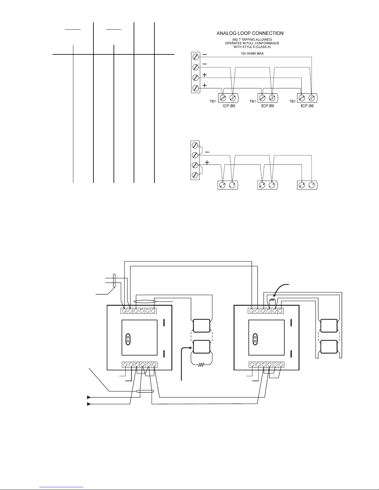
Analog Loop
The ICP-B6 communicates with the MXL
through its analog addressable loops. These
loops are on either the MMB or on the optional ALD-2I module of the MOM-4. They
may be wired for Class A (Style 6) or Class B
(Style 4). Figure 1 shows both wiring types
and the connections to either the MMB or to
the MOM-4 when the ALD-2I module is used.
The table on the following page lists the
maximum output currents allowed.
Siemens Building Technologies, Ltd.
Fire Safety & Security Products
2 Kenview Boulevard
Brampton, Ontario
L6T 5E4 Canada
Page 2
The ICP-B6 module can be used in four
different ways:
1. Using the ICP-B6 as an NAC Module
This notification appliance application uses the
principle of polarity reversal when there is an
alarm. Figure 2 shows the polarity connection
in a supervisory condition. When using the
ICP-B6 as a supervised NAC output module
with notification appliance devices, cut jumper
JP2. Refer to Figure 2 for additional connection and jumper information, and to P/N 315096363 for a list of compatible devices.
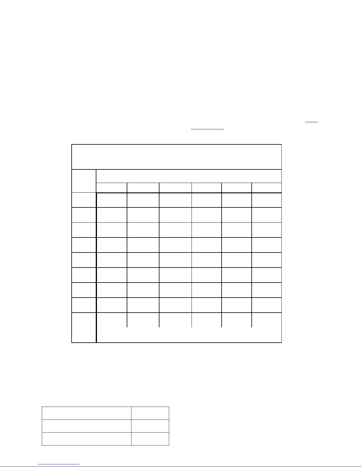
MAXIMUM ALLOWABLE I CP-B6 OUTPUT CIRCUIT LINE RESISTANCE
FOR SPECIFIED DC RISER CURRENT AND LINE RESISTANCE
MAXIMUM
DC RISER
CURRENT
(in Amps)
8 2.46 1.67 .33
7 2.53 1.83 .66
6 2.60 2.00 1.00
0.1 Ohm 0.25 Ohm 0.5 Ohm 0.75 Ohm 1 Ohm 1.5 Ohms
DC RISER RESISTANCE (in Ohms)
When used as an NAC module, the output
circuit is power limited. The ICP-B6 maximum
current is 1.5A at 24 VDC. If the 24 VDC is
lost or the NAC line is broken or shorted, the
trouble condition INPUT DEVICE RESPONSE
TOO LOW displays at the MXL/MXLV control
panel. Refer to Figures 3 and 4 for the connections used with the TRI-60/B6 module and
the PSR-1 module, respectively. See the
Line
Resistance chart for the allowable line
resistance for each ICP-B6 output circuit.
-- -- --
-- -- --
-- -- --
5 2.67 2.16 1.33 .5
4 2.73 2.33 1.67 1.00 .33
3 2.80 2.50 2.00 1.50 1.00
2 2.86 2.67 2.33 2.00 1.67 1.00
1 2.93 2.83 2.67 2.50 2.33 2.00
.5 2.96 2.92 2.83 2.75 2.67 2.50
MAXIMUM LOOP RESISTANCE FOR EACH ICP-B6 ON RISER
NOTES:
1. Resistances specified are for both wires.
2. If higher currents are required, Siemens Industry, Inc. recommends using a local auxiliary
supply which is UL listed for fire protection signaling use. The supply should be rated between
24 and 27.3 VDC.
ELECTRICAL RATINGS
tnerruCeludoMCDV5evitcAAm0
-- --
--
--
tnerruCeludoMCDV42evitcAAm01
tnerruCeludoMCDV42ybdnatSAm01
2
Page 3
ALD-2I ALD-2I
MOM-4
TB2
LOOP 1 LOOP 2 LOOP 1 LOOP 2 LOOP 1 LOOP 2
4
3
2
1
4
3
2
1
8
7
6
5
8
7
6
5
4
3
2
1
4
3
2
1
MOM-4
TB1
MMB
TB2
8
7
6
5
8
7
6
5
MMB
TB3
4
3
2
1
4
3
2
1
4
3
2
1
4
3
2
1
ANALOG LOOP CONNECTION
OPERATES IN FULL CONFORMANCE WITH STYLE 4 (CLASS B)
*
(T-TAPPINGALLOWED)
100 OHMS MAX
*
SUPERVISED, POWER LIMITED PER NEC 760
ALL WIRING MUST CONFORM TO NATI ONAL AND
SUPERVISED
DC INPUT RATED
24 - 27.3 VDC FWR
SUPV: 12mA
ACTIVATED: 1.5A MAX
MODULE INPUT SUPPLY
FROM PS-35, PSR-1, OR
UL LISTED POWER SUPPLY
ALARM-SAF (Model BN4-002-UL)
MANUFACTURED BY
ELECTRICAL:
INPUT DC SUPPLY:
SUPERVISORY OUTPUT:
ACTIVATED:
LOOP RESISTANCE 100 OHMS MAX
18 AWG MINIMUM WIRE
NO EOL DEVICE REQUIRED
LOCAL ELECTRICAL CODES
-
ANALOG
LOOP
CONNECTION
+
TB1 TB1
TB2
EARTH
SHIELD
SUPERVISED STROBE ACTIVATION - SPECIAL APPLICATION
SUPV: 9VDC, .5mA
ACTIVATED: 16-32V UNFILTERED FULL WAVE RECTIFIED, 1.5A MAX
POLARITY SHOWN IN SUPV. CONDITION
1 1
3 3
2 2
----
++++
ICP-B6 ICP-B6
PROGRAM
PLUG
6
5
4
-
+
24-27.3 VDC, 18mA MAX
9 VDC, 0.5mA
SPECIAL APPLICATION
16-32V UNFILTERED FULL WAVE RECTIFIED
1.5A, POWER LIMITED
ICP-B6 MODULE IS USED FOR
NAC SUPERVISION AND ACTIVATION
12 12 12
TB1 TB1 TB1
ICP-B6 ICP-B6 ICP-B6
*JUMPERS CAN BE REMOVED FROM MMB-3 WITH CSGM CONFIGURATION
Figure 1
Analog Loop Connections
STYLE Y
POWER
LIMITED
6 6
5 5
4 4
-
JP2 JP2
+
JP1 JP1
+
+--
1
3
2
15K, 1/2W, 5%
EOL RESISTOR
P/N 140-820400
16-32 VDC
NAC UNITS
SEE TABLE 1
NOTES:
1. ALL WIRING MUST COMPLY WITH NATIONAL AND LOCAL CODES.
2. POSITIVE AND NEGATIVE GROUND FAULT DETECTED AT <5K OHMS FOR TERMINALS 3-6.
3. FOR SYNCHRONIZATION OF NOTIFICATIONAPPLIANCES USE EITHER DSC, DSC-W, OR PAD-3.
EARTH
SHIELD
NAC SUPERVISION AND ACTIVATION
PROGRAM
PLUG
TB2
6
5
ICP-B6 MODULE IS USED FOR
STYLE Z
15K, 1/2W, 5% EOL RESISTOR
P/N 140-820400
-
++
--
+
+
+--
1
3
2
4
Figure 2
ICP-B6 Used as a Strobe Module
3
Page 4

Figure 3
ICP-B6 Connections When Using TRI-60/B6
Figure 4
ICP-B6 Connections Using PSR-1
4
Page 5

FROM MXL MMB OR
ALD-2I ON MOM-4
(12 MAX ICP-B6
MODULES PER LOOP)
(SUPERVISED)
ICP-B6 DC SUPPLY
FROM MMB, PSR-1, OR
UL LISTED POWER SUPPLY
MANUFACTURED BY ALARM-SAF
Model BN4-002-UL (SUPERVISED)
-
+
ANALOG LOOP
CONNECTION
+
-
SHIELD
PROGRAM
PLUG
-
5
4
24 OHMS MAX
-
+
3
2
SHIELD
+
-
+
-
SHIELD
+
TB2
1
10K, 1/2W, +/-5%
EOL RESISTOR
P/N 140-112172
AT LAST STATION
WARDEN'S STATIONS
MODELS FT-301 SERIES
AND FT-302 SERIES
+
-
+
-
SUPERVISED
POWER LIMITED
SHIELD
SHIELD
TB1 TB1
1 1
2 2
----
++++
ICP-B6 ICP-B6
PROGRAM
PLUG
SHIELD
TO
6
EARTH
5
6 6
3 3
5 5
4 4
JP2 JP2
JP1 JP1
-
-
+
+
TB2
1
3
2
4
WHITE WHITE
WHITE
WHITE
FJ-303
FJ-303
BLACK BLACK
BLACK
BLACK
EARTH
TO
SHIELD
6
SHIELD SHIELD
FROM PREVIOUS ICP-B6, OCC-1,
OR TBM
(20 OHMS MAXIMUM
LINE RESISTANCE)
COMMON TALK RISER
RISER
NOMINAL VOLTAGE:
MAXIMUM CURRENT:
NOTES:
1. THE SHIELD ON THE COMMON TALK LINE MUSTBE CONTINUOUS
AND CONNECTED ONLY TO DC COMMONAT CONTROL PANEL.
2. ALL WIRING MUST CONFORM TO NATIONAL AND LOCAL CODES.
3. POSITIVE AND NEGATIVE GROUND FAULT DETECTED AT <5K OHMS FOR TERMINALS 3-6.
17.5 VDC
175 mA
ICP-B6 Used as a Telephone Zone
2.
Using the ICP-B6 as a Telephone Zone
When the ICP-B6 is used as a telephone zone
module, the 24 VDC provides supervision,
trouble, and call-in conditions. If the 24 VDC is
lost, the trouble condition INPUT DEVICE
RESPONSE TOO LOW displays at the MXL/
MXLV and an LED for that zone lights at the
VSM-1 module.
The supervised telephone common talk riser
starts at the TBM module in the MME-3 backbox. The Class B shielded cable connects
continuously to each ICP-B6 with a 5.6K end of
line device. Tie the shield of these riser wires
and the shield of the zone output wires together
using terminal 5 of TB2 and isolate them from
the system circuits and the earth ground.
Connect the supervised individual zone output
connections from each ICP-B6 to the field
telephone with shielded cable. Terminate
them at the last station with a 10K ohm end of
line resistor. As with the common talk line
described in the paragraph above, be sure
that the shield is continuous and isolated
10K, 1/2W, +/-5%
EOL RESISTOR
P/N 140-112172
AT LAST FJ-303
Figure 5
SHIELD
ELECTRICAL:
INPUT DC SUPPLY:
SUPERVISORY OUTPUT:
ACTIVATED OUTPUT:
5.6K, 1/2W, +/-5%
EOL RESISTOR
20.5 TO 30 VDC, 18mA MAX
8V, .8mA
11V, 70mA
18 AWG MINUMUM
BELDON 8760 OR EQUIVALENT
OR AS REQUIRED BY
THE LOCAL AUTHORITY
HAVING JURISDICTION
from both system circuits and earth
ground and that the shields are connected
together using terminal 5 of TB-2.
3. Using the ICP-B6 as a 70 Volt Speaker
Zone
When the ICP-B6 is used as a speaker zone,
the 24 VDC provides the supervision. If the 24
volts is lost or there is an open or shorted
speaker output line, the trouble condition
INPUT DEVICE RESPONSE TOO LOW
displays at the MXL/MXLV and the related
zone LED on the VSM-1 lights.
The 70.7V RMS audio input comes from the
amplifier via the ASC-2 Amplifier Supervision
card. The ASC-2 supervises the audio connection path to the ICP-B6 and provides up to
100 watts of power. The ASC-2 can be used
as Style Y (Class B) or Style Z (Class A). Refer
to the ASC-2 Instructions, P/N 315-092085.
When the ICP-B6 is used as a speaker zone,
the output speaker lines are supervised and
power limited. The audio output cannot exceed
5
Page 6

25 watts. Connect the speaker output as either
Style Y (Class B) or Style Z (Class A). Figure 6
gives the approximate decibel loss for the total
speaker zone wire length for various wire
gauge sizes.
When using the ICP-B6 as a 70.7V RMS
speaker zone, cut the JP1 jumper. (See
Figure 8.)
4. Using the ICP-B6 as a 25 Volt Speaker
Zone
When the ICP-B6 is used as a speaker zone,
the 24 VDC provides the supervision. If the 24
volts is lost or there is an open or shorted
speaker output line, the trouble condition
INPUT DEVICE RESPONSE TOO LOW
displays at the MXL/MXLV and the related
zone LED on the VSM-1 lights.
The 25V RMS audio input comes from the
amplifier via the ASC-2 Amplifier Supervision
card. The ASC-2 supervises the audio connection path to the ICP-B6 and provides up to
100 watts of power. The ASC-2 can be used
as Style Y (Class B) or Style Z (Class A).
Refer to the ASC-2 Instructions, P/N 315-
092085.
Figure 6
Approximate Speaker Zone Wire Loss
with the 70.7V Option
When the ICP-B6 is used as a speaker zone,
the output speaker lines are supervised and
power limited. The audio output cannot
exceed 35 watts. Connect the speaker output
as either Style Y (Class B) or Style Z (Class
A). Figure 7 gives the approximate decibel
loss for the total speaker zone wire length for
various wire gauge sizes.
When using the ICP-B6 as a 25V RMS
speaker zone, cut the JP2 jumper (See
Figure 9).
Figure 7
Approximate Speaker Zone Wire Loss
with the 25V Option
6
Page 7

SUPERVISED ANALOG
100 OHMS MAX
+
-
SHIELD
AUDIO RISER CONNECTIONS
SUPERVISORY: 9 VDC, 0.5mA
AUDIO OUTPUT:70.7 VRMS,
OR ALD-2I ON MOM-4
MAXIMUM OF 12 ICP-B6
MODULES PER LOOP
NFPASTYLE Y
100 WATTSMAX
LOOP CONNECTION
FROM MXL, MMB,
SEE MXL MANUAL
(P/N 315-092036)
15K, 1/2W, +/-5%
EOL RESISTOR
P/N 140-820400
ASC-2
-
+
16161717181819
OBSERVE
CONNECTION
POLARITY
ICP-B6 DC SUPPLY FROM MMB, PSR-1,
SUPERVISED
RISER
OR UL LISTED POWER SUPPLY
MANUFACTURED BYALARM-SAF
(Model BN4-002-UL)
All wiring must comply with national and local codes.
ELECTRICAL:
INPUT DC SUPPLY:
SUPERVISORY OUTPUT:
ACTIVATEDOUTPUT:
TB1
1
3
2
--
++
ICP-B6
PROGRAM
PLUG
TB2
6
5
4
EARTH
SHIELD
+
-
24-27.3 VDC, 18mA MAX
9 VDC MAX, 0.5mA
70.7 V, 25 WATTS MAX
DC INPUT RATING
24-27.3 VDC, 18 mA
STYLE Z
SUPERVISED
SPEAKER ZONE CONNECTIONS
SUPV: 9 VDC, 0.5 mA
ACTIVATED:70.7 VRMS, 25 W MAX
6
5
4
JP2
JP1
70.7 VRMS SPEAKER UNITS:
+
+--
1
3
2
ANY UL LISTED FIRE
PROTECTION SIGNALING
SPEAKER RATED 70.7 V
IS COMPATIBLEWITH
SUPERVISED BY ICP-B6 MODULES
THIS CIRCUIT
EARTH
24K, 1/2 W, +/-5%
EOL RESISTOR
P/N 140-820405
SPEAKER ZONE CONNECTIONS
ACTIVATED:70.7 VRMS, 25 W MAX
TB1
1
3
2
5
4
--
++
ICP-B6
PROGRAM
PLUG
TB2
SHIELD
ORIGINAL NFPASTYLE Z
AUDIO RISER CONNECTIONS
TO ICP-B6 ZONE MODULES
+--
6
3
2
5
4
ASC-2
19
STYLE Y
SUPERVISED
SUPV: 9 VDC, 0.5 mA
10 OHMS MAX
6
JP2
JP1
+
1
TB2
EARTH
SHIELD
CAPACITOR
COUPLED
70.7 VRMS
SPEAKERS
+++
-- -
TB1
15K, 1/2W, 5%
EOL RESISTOR
P/N 140-820400
FIRST ICP-B6
6
5
4
1
++
TB2
6
EARTH
SHIELD
ASC-2 RISER CAN NOT
BE T-TAPPED
JP1 JP1
+
+--
1
3
2
6
3
2
5
4
--
ICP-B6
PROGRAM
PLUG
+
+--
1
3
2
5
4
24K, 1/2 W, +/-5%
EOL RESISTOR
ON LAST ICP-B6
SPEAKER ZONE
MODULE
P/N 140-820405
LAST ICP-B6
TB2
6
5
EARTH
SHIELD
JP2
JP1
4
3
15K, 1/2W, 5%
EOL RESISTOR
P/N 140-820400
+
+--
1
2
Figure 8
ICP-B6 Used as a 70.7V Speaker Zone
SUPERVISED ANALOG
100 OHMS MAX
+
-
SHIELD
AUDIO RISER CONNECTIONS
SUPERVISORY: 9 VDC, 0.5mA
AUDIO OUTPUT:25 VRMS,
OBSERVE
CONNECTION
POLARITY
ICP-B6 DC SUPPLY FROM MMB, PSR-1,
LOOP CONNECTION
FROM MXL, MMB,
OR ALD-2I ON MOM-4
MAXIMUM OF 12 ICP-B6
MODULES PER LOOP
SEE MXL MANUAL
(P/N 315-092036)
15K, 1/2W, +/-5%
EOL RESISTOR
P/N 140-820400
TB1
1
3
2
NFPASTYLE Y
100 WATTSMAX
4
--
++
ICP-B6
PROGRAM
PLUG
ASC-2
-
+
16161717181819
SUPERVISED
RISER
EARTH
SHIELD
TB2
6
3
5
4
+
OR UL LISTED POWER SUPPLY
MANUFACTURED BYALARM-SAF
(Model BN4-002-UL)
-
DC INPUT RATING
24-27.3 VDC, 12 mA
All wiring must comply with national and local codes.
ELECTRICAL:
INPUT DC SUPPLY:
SUPERVISORY OUTPUT:
ACTIVATEDOUTPUT:
24-27.3 VDC, 18mA MAX
9 VDC MAX, 0.5mA MAX
25 V, 35 WATTS MAX
STYLE Z
SUPERVISED
SPEAKER ZONE CONNECTIONS
SUPV: 9 VDC, 0.5 mA
ACTIVATED:25 VRMS, 35 W MAX
6
5
JP2
JP1
25 VRMS SPEAKER UNITS:
+
+--
1
2
ANY UL LISTED FIRE
PROTECTION SIGNALING
SPEAKER RATED 25 V
IS COMPATIBLEWITH
SUPERVISED BY ICP-B6 MODULES
THIS CIRCUIT
EARTH
24K, 1/2 W, +/-5%
EOL RESISTOR
P/N 140-820405
SPEAKER ZONE CONNECTIONS
ACTIVATED:25 VRMS, 35 W MAX
TB1
1
3
2
5
4
--
++
ICP-B6
PROGRAM
PLUG
TB2
SHIELD
ORIGINAL NFPASTYLE Z
AUDIO RISER CONNECTIONS
TO ICP-B6 ZONE MODULES
+--
6
3
2
5
4
ASC-2
19
STYLE Y
SUPERVISED
SUPV: 9 VDC, 0.5 mA
10 OHMS MAX
6
JP2
JP1
+
1
TB2
EARTH
SHIELD
CAPACITOR
COUPLED
25 VRMS
SPEAKERS
+++
-- -
TB1
15K, 1/2W, 5%
EOL RESISTOR
P/N 140-820400
FIRST ICP-B6
6
5
4
1
++
TB2
6
EARTH
SHIELD
ASC-2 RISER CAN NOT
BE T-TAPPED
JP1 JP1
+
+--
1
3
2
6
3
2
5
4
--
ICP-B6
PROGRAM
PLUG
+
+--
1
3
2
5
4
24K, 1/2 W, +/-5%
EOL RESISTOR
ON LAST ICP-B6
SPEAKER ZONE
MODULE
P/N 140-820405
LAST ICP-B6
TB2
6
5
EARTH
SHIELD
JP2
JP1
4
3
15K, 1/2W, 5%
EOL RESISTOR
P/N 140-820400
+
+--
1
2
Figure 9
ICP-B6 Used as a 25V Speaker Zone
7
Page 8

MOUNTING
(See Figure 10)
1. Use a standard 3 1/2-inch deep, double
gang electrical switchbox or a 4-inch
1
square electrical box that is 2
1
deep with either a 1
extension or a 1
/2-inch deep
1
/4 -inch deep plaster ring
/2 inches
extension.
2. Connect the field wiring. Insert the ICP-B6
into the box and fasten the module plate
to the box.
NOTE: When using the double gang
switchbox or the plaster ring
extension, use the same four
screws to fasten both the module and the blank plate (user
supplied).
3. Cover the module front plate with a 4-inch
blank plate (user supplied) and fasten
with two plate screws.
Siemens Industry, Inc.
Building Technologies Division
Florham Park, NJ
P/N 315-095306-10
Figure 10
Mounting the ICP-B6
Siemens Building Technologies, Ltd.
Fire Safety & Security Products
2 Kenview Boulevard
Brampton, Ontario
L6T 5E4 Canada
 Loading...