

Siemens HS-MC Series Installation Instructions Manual

MULTI-CANDELA FOUR WIRE HORN STROBE APPLIANCES
IMPORTANT
installed in accordance with all applicable national and local fire alarm
codes and any other required regulatory agencies.
Series HS-MC Multi-Candela Horn Strobe provides four selectable
candela settings (15, 30, 75, 110). The HS-MC allows for independent
operation of the strobe circuit and the horn circuit. It is the ideal choice
for retrofit applications as well as new installations. The HS-MC
appliance is UL Listed under Standard 1971 for Signaling Appliances
for the Hearing Impaired and UL Standard 464 for Audible Signal
Appliances. The HS-MC is also ULC Listed under Standard CAN/ULCS526-02 for Visual Signaling Appliances and Standard CAN/ULCS525-99 for Audible Signaling Appliances for Fire Alarm Systems. It is
listed for indoor use only
backbox, 100mm European backbox or MT-SUR-BOX surface
backbox (See wiring and mounting information). This appliance is
listed for wall mounting only
flashtube with solid state circuitry enclosed in a polycarbonate lens to
provide maximum visibility and reliability for effective visible signaling.
Siemens Series HS appliances provide a selectable continuous or
Code 3 horn tone and non-synchronized strobe when connected
directly to a Fire Alarm Control Panel (FACP). They can also provide a
synchronized Code 3 (or March Time) horn tone and synchronized
strobe when connected to a notification appliance circuit running the
Siemens sync protocol. HS appliances can be field set for High (HI),
medium (MED) dBA or low (LO) dBA sound output. .
SPECIFICATIONS:
– All audible and visual signaling appliances must be
and can be mounted to double-gang, 4”
. The HS-MC appliance uses a xenon
Model*
HS-MC 16.0-33.0 20.0-31.0 15/30/75/110
Description
Low 80 83 86 88 90 91
Continuous Horn Medium 85 88 91 93 95 97
High 88 91 93 97 99 100
Low 75 79 82 88 90 91
Code 3 Horn or Medium 80 84 86 93 95 97
March Time** High 84 87 89 97 99 100
Operating Voltage (Special Application)
Volume
Per UL 1971
(VDC/VRMS)
16.0VDC 24VDC 33.0VDC 20.0VDC 24VDC 31.0VDC
INSTALLATION INSTRUCTIONS
(WALL MOUNT VERSION)
Table 1: UL/ULC Listed Models and Ratings
*Available in red and white.
Table 2: dBA Sound Output for 24VDC Models
Reverberant Per UL 464 Anechoic dBA @ 10 Ft. Per CAN/ULC-S525-99
**Available in sync mode only.
NOTE: The Code 3 temporal pattern (1/2 second on, 1/2 second off,
1/2 second on, 1/2 second off, 1/2 second on, 1-1/2 off and repeat) is
specified by ANSI and NFPA 72 for standard emergency evacuation
signaling. The Code 3 Horn should be used only for fire
evacuation signaling and not for any other purpose.
The HS-MC is designed for use with either filtered DC or unfiltered fullwave-rectified (FWR) input voltage. All inputs are polarized for
compatibility with standard reverse polarity supervision of circuit wiring
by an FACP.
NOTE: All Canadian Installations should be in accordance with the
Canadian Standard for the Installation of Fire Alarm Systems –
CAN/ULC-S524-01 and Canadian Electrical Code, Part 1. Final
acceptance is subject to authorities having jurisdiction (AHJ).
NFPA 72/ANSI 117.1 conform to ADAAG Equivalent Facilitation
Guidelines in using fewer, higher intensity strobes within the same
protected area.
NOTE: Refer to P/N 315-096363 for the maximum number of
appliances on a single notification appliance circuit.
Voltage Range Per
CAN/ULC-S526-02
(VDC/VRMS)
Strobe
Candela
(cd)
Siemens Building Technologies, Inc. P84391-003B
8 Fernwood Road Sheet 1 of 4
Florham Park, New Jersey 07932
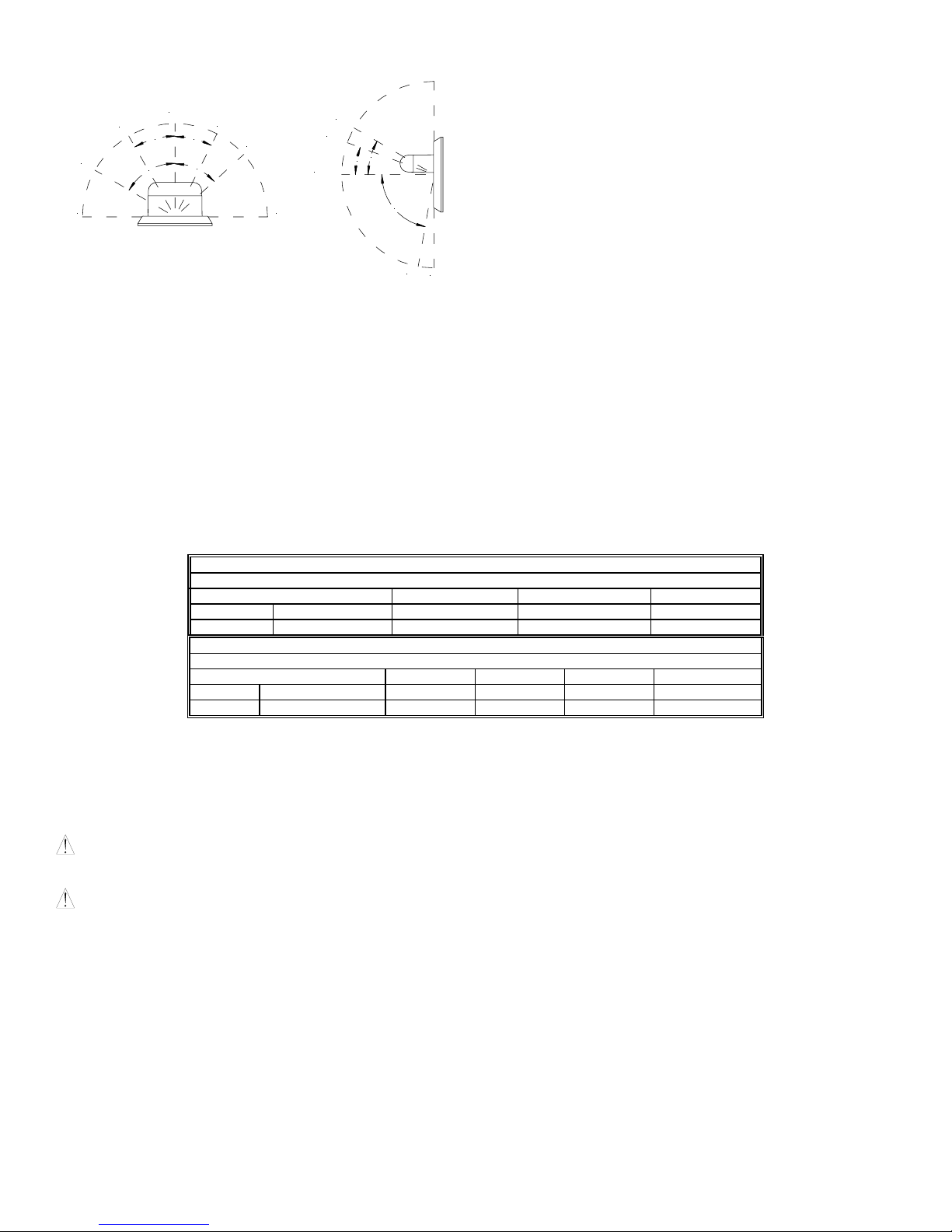
Figure 1: ULC Directional Characteristics
85dB
-6dB
-3dB
95dB
30°
60°
-3dB
27°
48°
-6dB
95dB
-3dB
-6dB
3. This model is UL/ULC Listed for indoor use with a temperature
range of +32°F to +120°F (0°C to +49°C) and maximum humidity
of 93% ± 2% RH. The effect of shipping and storage
temperatures shall not adversely affect the performance of the
appliance when it is stored in the original cartons and not
subjected to misuse or abuse.
30°
20°
81dB83dB
NOTES:
1. The strobe will produce 1 flash per second over the Input Voltage
range.
2. This horn/strobe model meets the required light distribution
patterns defined in UL 1971 and ULC-S526-02.
When calculating the total current: Use Tables 3 & 3A to determine the highest value of “RMS Current” for an individual HS-MC then multiply the value
by the total number of HS-MC Appliances. Be sure to add the currents for any other appliances powered by the same source and to include any
required safety factors.
Note: These notification appliances are UL Listed as “Special Application”. They are intended to be used only with Siemens notification appliance
circuits.
CANDELA SETTING WILL DETERMINE THE CURRENT DRAW OF THE PRODUCT.
Input Voltage Lo Med Hi
DC 16-33VDC 0.027 0.068 0.110
FWR 16-33VRMS 0.041 0.050 0.094
Input Voltage 15cd 30cd 75cd 110cd
DC 16-33VDC 0.064 0.098 0.175 0.233
FWR 16-33VRMS 0.108 0.164 0.268 0.368
THESE APPLIANCES WERE TESTED TO THE VOLTAGE LIMITS OF 16.0-33.0 VOLTS FOR 24V MODELS USING FILTERED DC OR UNFILTERED
FULL-WAVE-RECTIFIED VOLTAGE. DO NOT APPLY VOLTAGE OUTSIDE OF THIS RANGE.
Note: Refer to the installation instructions for the appropriate NAC to find the maximum allowed voltage drop. Use this value along with the current draw
for the appliance to determine the allowable wire resistance. The maximum wire resistance between strobes shall not exceed 35 ohms.
CAUTION: The strobe is not designed to be used on coded systems in which the applied voltage is cycled on and off.
NOTE: The horn circuit is compatible with coded systems only if the unit is wired for independent horn and strobe operation per figure 4.
WARNING: MAKE SURE THAT THE TOTAL RMS CURRENT REQUIRED BY ALL APPLIANCES THAT ARE CONNECTED TO THE SYSTEM’S
PRIMARY AND SECONDARY POWER SOURCES DO NOT EXCEED THE POWER SOURCES’ RATED CAPACITY OR THE CURRENT RATINGS
OF ANY FUSES ON THE CIRCUITS TO WHICH THESE APPLIANCES ARE WIRED. OVERLOADING POWER SOURCES OR EXCEEDING FUSE
RATINGS COULD RESULT IN LOSS OF POWER AND FAILURE TO ALERT OCCUPANTS DURING AN EMERGENCY, WHICH COULD RESULT IN
PROPERTY DAMAGE AND SERIOUS INJURY OR DEATH TO YOU AND/OR OTHERS.
Siemens Building Technologies, Inc. P84391-003B
8 Fernwood Road Sheet 2 of 4
Florham Park, New Jersey 07932
80°
-3dB
-6dB
Table 3: Current Ratings (Horn Only)
Maximum RMS Current (Amps)
Table 3A: Current Ratings (Strobe Only)
Maximum RMS Current (Amps)
 Loading...