

Siemens HOTEL SOLUTION HTC3.2 Series, HOTEL SOLUTION HTC3.2/BW, HOTEL SOLUTION HTC3.2/VB, HOTEL SOLUTION HTC3.2/VW, HOTEL SOLUTION HTC3.2/BB Quick Start Manual
Page 1
s
6
320
HOTEL SOLUTION™
Room operator unit
HTC3.2/..
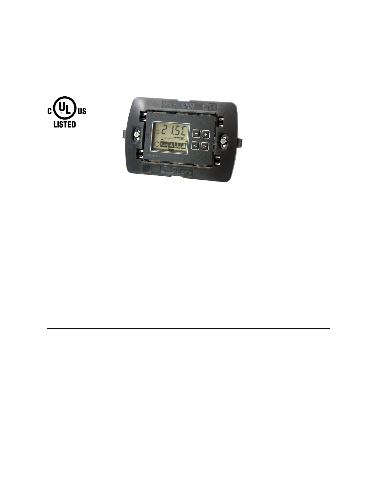
Room unit to operate individual room control systems in hotel rooms
• Displays room temperature setpoint and setpoint adjustment
• Individual setpoint adjustment with "plus" and "minus" membrane switches
• Individual manual fan-speed selection for fan control (up to 3 speeds) or
selection of "Auto" operating mode
• Measurement of room temperature with a built-in or externally connected
temperature sensor
Application
The HTC3.2 operator unit for control of indoor room conditions is used in conjunction
with the HRC3.1/HRC3.2 room controllers. The room operator unit detects the
temperature and transmits it to the HRC3.1/HCR3.2 room controllers for room
temperature control. The room operator unit displays the operating mode in the hotel
room and can be used to operate the fan coil unit, either manually or automatically via
the connected room controller.
CM2N6320en
01.09.2008
Building Technologies
Page 2

Function
The HTC3.2 room operator unit communicates with the HRC3.1 or HRC3.2 room
controller via a serial port, performing the following functions:
• Displays the room temperature setpoint
• Transmits the manual room temperature setpoint adjustment
• Displays the manual room temperature setpoint adjustment
• Transmits the manually set fan speed
• Displays the manual or automatic fan speed
• Transmits the "Auto" operating mode signal for automatic selection of the fan speed
• Measures and transmits the room temperature detected via the built-in 10 kΩ NTC
room sensor or via an externally connected NTC 10 kΩ room sensor
Types
HTC3.2/BB Room operator unit for Bticino Living cover plate range
HTC3.2/BW Room operator unit for Bticino Light cover plate range
HTC3.2/VB Room operator unit for Vimar Idea cover plate range
HTC3.2/VW Room operator unit for Vimar Plana or Ikon cover plate range
Ordering
When ordering, please specify the quantity, product name and type code:
30 Ro om units HTC3.2/BB
Example
The following items depend on the desired overall program and installation type and
must be ordered separately from the corresponding frame supplier:
• Flush-mounted or cavity wall box for integration.
• Cover frame of the corresponding supplier with desired surface.
Compatibility
Name Type Data sheet
Room controller
HRC3.1
N6313
Room controller
HRC3.2
N6314
Room operator unit on same room bus
HTC3.2/..
N6320
Cable temperature sensor
HSE1.1
N6221
Room temperature sensor in VIMAR idea housing
HSE1.2
N6221
Magnetic card reader on same room bus
HMR3.1/A
N6334
Magnetic card holder on same room bus
HMH3.1/A
HML3.1/A
N6335
Transponder card reader on same room bus
HTR3.1/B
N6336
Transponder card holder on same room bus
HTH3.1/B
N6337
Chip card reader on same room bus
HCR3.2/..
N6332
Chip card holder on same room bus
HCH3.2/..
N6333
2/10
Building Technologies HTC3.2/.. - Room operator unit CM2N6320en
01.09.2008
Page 3
Mechanical design
The room operator unit comprises:
• Printed circuit board with the electronic circuit, LCD display, buttons for operation,
with terminal block and DIP switches
• Base frame:
− Bticino Living/Type L4703 for HTC3.2/BB
− Bticino Light/Type N4703 for HTC3.2/BW
− Vimar Idea/Type 16713 for HTC3.2/VB
− Vimar Plana or Ikon/Type 20613 for HTC3.2/VW
The printed circuit board is permanently glued into the base frame and cannot,
therefore, be replaced.
Note
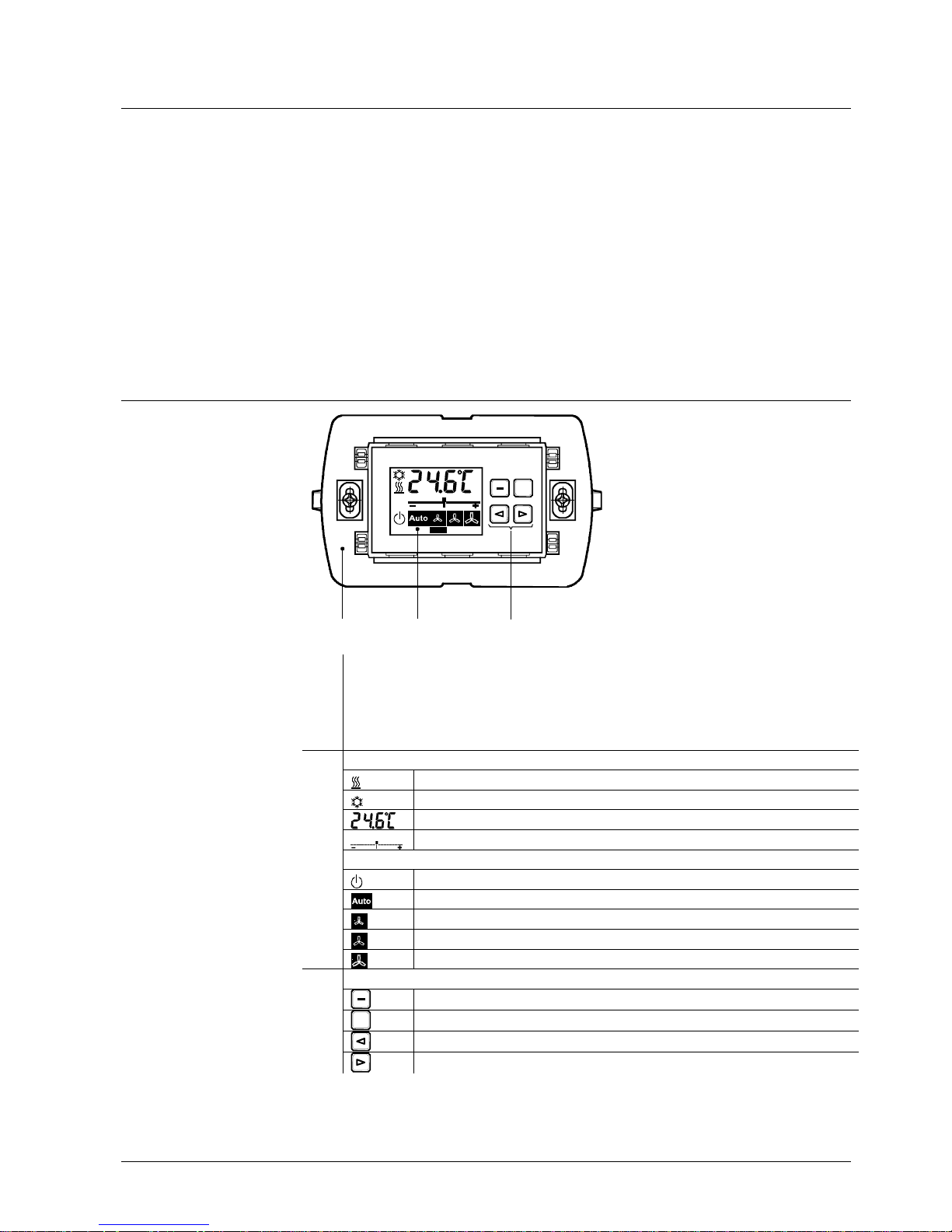
Operator controls, connections and display elements
+
12 3
6320Z01de
Front view
1 Base frame with fixing screws
• Bticino Living/Type L4703 for HTC3.2/BB
• Bticino Light/Type N4703 for HTC3.2/BW
• Vimar Idea/Type 16713 for HTC3.2/VB
• Vimar Plana or Ikon/Type 20613 for HTC3.2/VW
2
Display
Heating symbol
Cooling symbol
Temperature setpoint display (digits) in °C or °F
Setpoint adjustment indicator (bar)
Display fan status
= Off
Automatic control
Stage 1
Stage 2
Stage 3
3
Buttons for operation
Pushbutton for reducing predefined setpoint in steps of 0.5 K or 1.0 K
+
Pushbutton for increasing predefined setpoint in steps of 0.5 or 1.0 K
Pushbutton for gradually decreasing fan speed
Pushbutton for gradually increasing fan speed
Key
3/10
Building Technologies HTC3.2/.. - Room operator unit CM2N6320en
01.09.2008
Page 4
The guest can use the room unit to do the following:
• Adjust the preset room temperature setpoint by ±2 K or by ±4 K in eight steps. The
step size of 0.5 or 1.0 K can be configured in the room controller. The eight
temperature-change increments are indicated by a horizontal scale across the center
of the LCD display panel.
• Enable fan speeds 1, 2 and 3 manually
• Change from manual to automatic mode ("Auto")
Switching to "Auto" causes the fan speed to be set automatically by the controller
(Speed 1, 2 or 3). The fan status is indicated by symbols across the bottom of the LCD
display panel.
The temperature setpoint valid for the room is displayed in digits on the LCD display
panel. Throughout the period for which the guest is checked in, the individual setpointsetting remains valid. It cannot be overwritten by the hotel service staff.
When the guest leaves the room (removing the access card from the card holder) the
system switches automatically to "Auto", and the "Precomfort" room operating mode
with the energy-saving function (widening of the deadband) comes into effect. When
the guest returns to the room, the "Auto" mode remains active and the "Comfort" room
operating mode, with the guest's personally selected setpoint adjustment, is restored.
In conjunction with the HOTEL SOLUTION system, the room temperature setpoints
preset for a given room are automatically re-instated when the guest checks out.
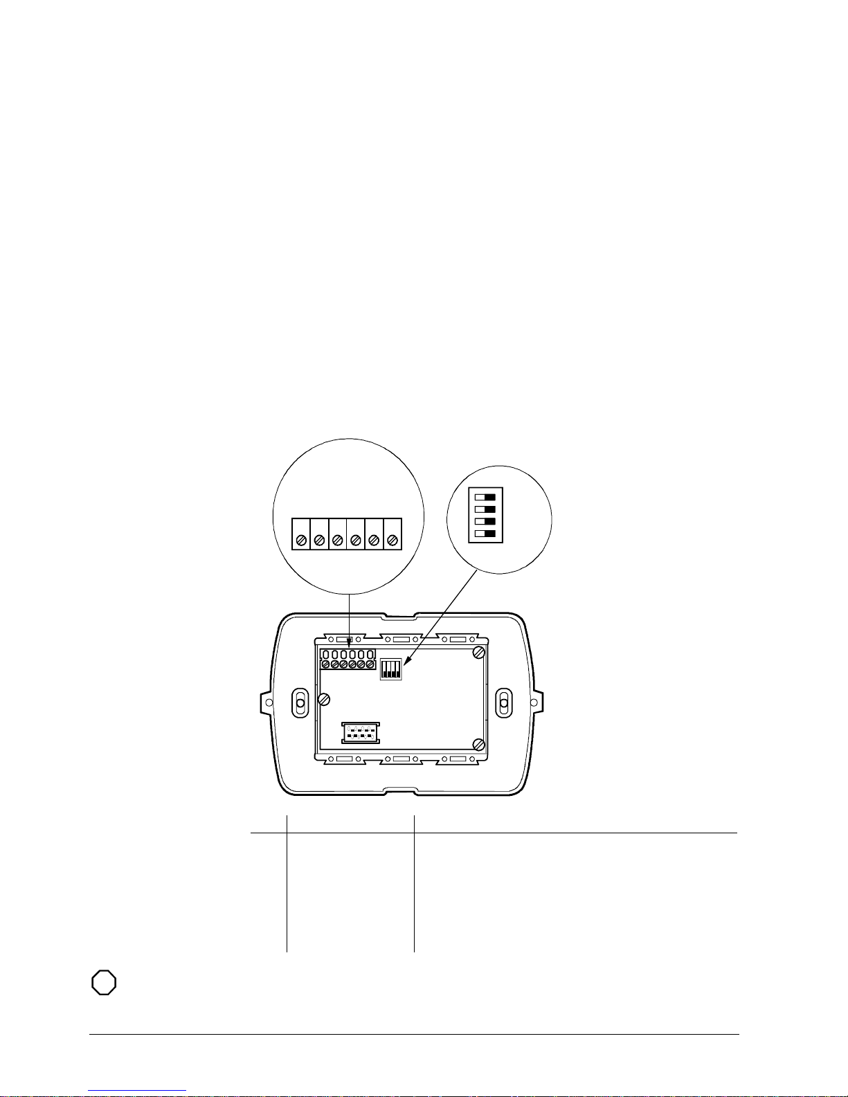
Rear view
ADR0
ADR1
PROT
TERM
ON
1 2 3 4 5 6
RS485+
RS485-
DC 12 V
DC 0 V
NTC 10 K
NTC 10 K
6320Z02
4
5
4 Terminal block • Connection to room controller
5 DIP switches • Bus address setting (ADR0, ADR1)
• Protocol setting
− PROT = 0, for HRC3.1/HRC3.2 room controller
− PROT = 1, for HRC3.8 room controller
• Control of RS485 bus termination resistance
− TERM = 0, bus termination resistance disabled
− TERM = 1, bus termination resistance enabled
Key
STOP
Important note
The bus termination resistance must be enabled on the last bus device only.
4/10
Building Technologies HTC3.2/.. - Room operator unit CM2N6320en
01.09.2008
Page 5
Engineering notes
Base frame The room unit is designed for flush wall mounting in conjunction with base-frames and
cover plates from various manufacturers:
• Bticino Living for HTC3.2/BB
• Bticino Light for HTC3.2/BW
• Vimar Idea for HTC3.2/VB
• Vimar Plana or Ikon for HTC3.2/VW
Up to 4 room units may be connected to one room controller.
STOP
Important note
The maximum permitted current associated with the supply voltage from the
HRC3.1/HRC3.2 room controller must not be exceeded.
(For further information, see data sheet CM2N6313 and CM2N6314.)
Addressing
The room temperature control algorithm is not in the room unit itself, but in the
controller application. To enable the room controller to communicate with the room unit,
the latter must be assigned with an address.
The addresses of the room operator units are set by DIP switch on the back of the
room comfort operator unit.
First room operating unit ADR0=0, ADR1 = 0
Second room operating unit ADR0=1, ADR1 = 0
Third room operating unit ADR0=0, ADR1 = 1
Fourth room operating unit ADR0=1, ADR1 = 1
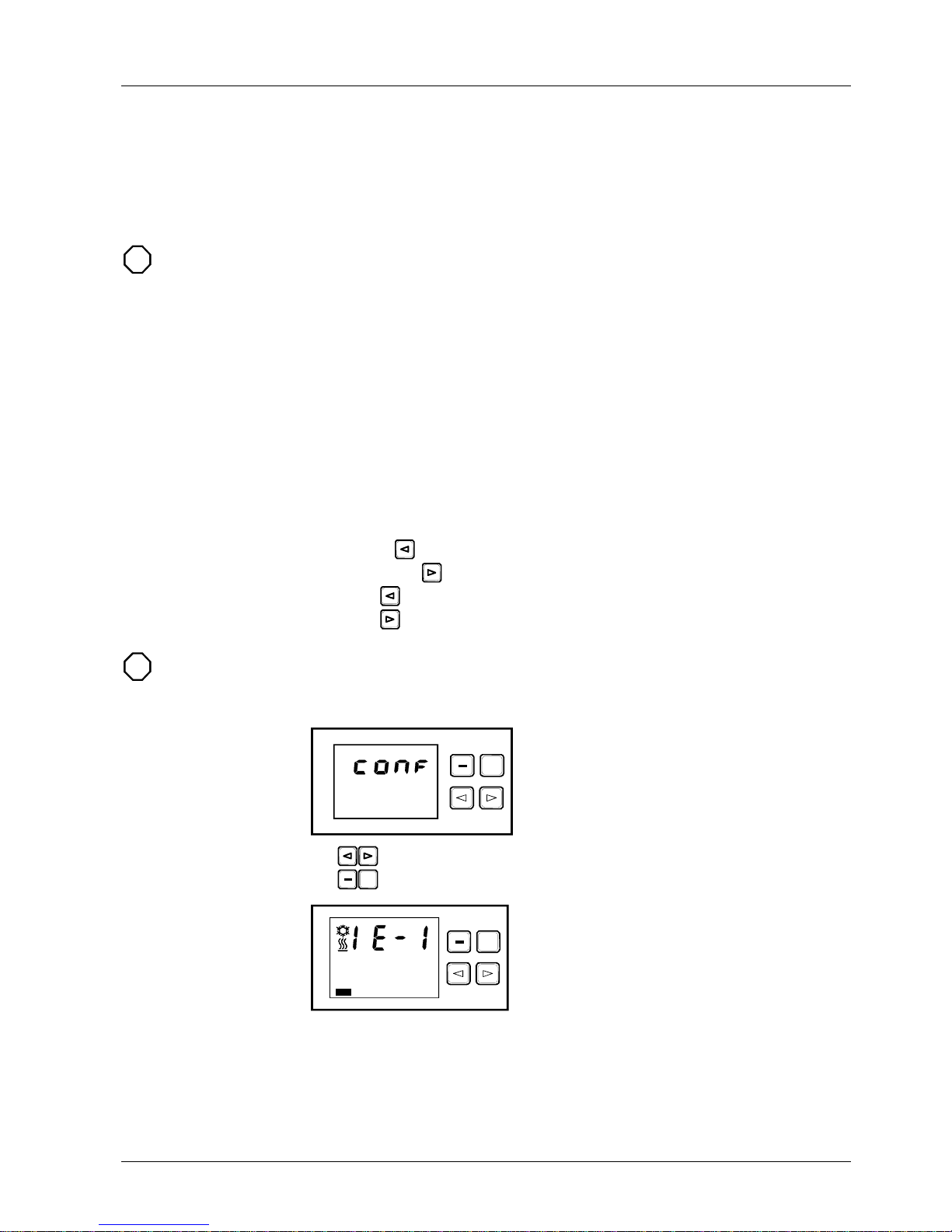
Configuration menu The room operator unit includes a configuration menu for setting certain parameters.
After a restart, the configuration menu can be displayed as follows:
1. Hold down
2. Press and hold
3. Release
4. Release
STOP
Important note
The configuration menu can only be displayed provided that no other buttons are
pressed when the room operator unit is restarted.
The configuration menu is identified as shown below.
Opening display
+
6320Z03
The
buttons are used to move to the previous and next menu respectively.
The
+
buttons are used for settings within a given menu.
Room sensors
+
6320Z04
For room temperature measurement, the internal or external room sensor can be
selected. The default is temperature measurement via the internal temperature sensor.
5/10
Building Technologies HTC3.2/.. - Room operator unit CM2N6320en
01.09.2008
Page 6
+
6320Z05
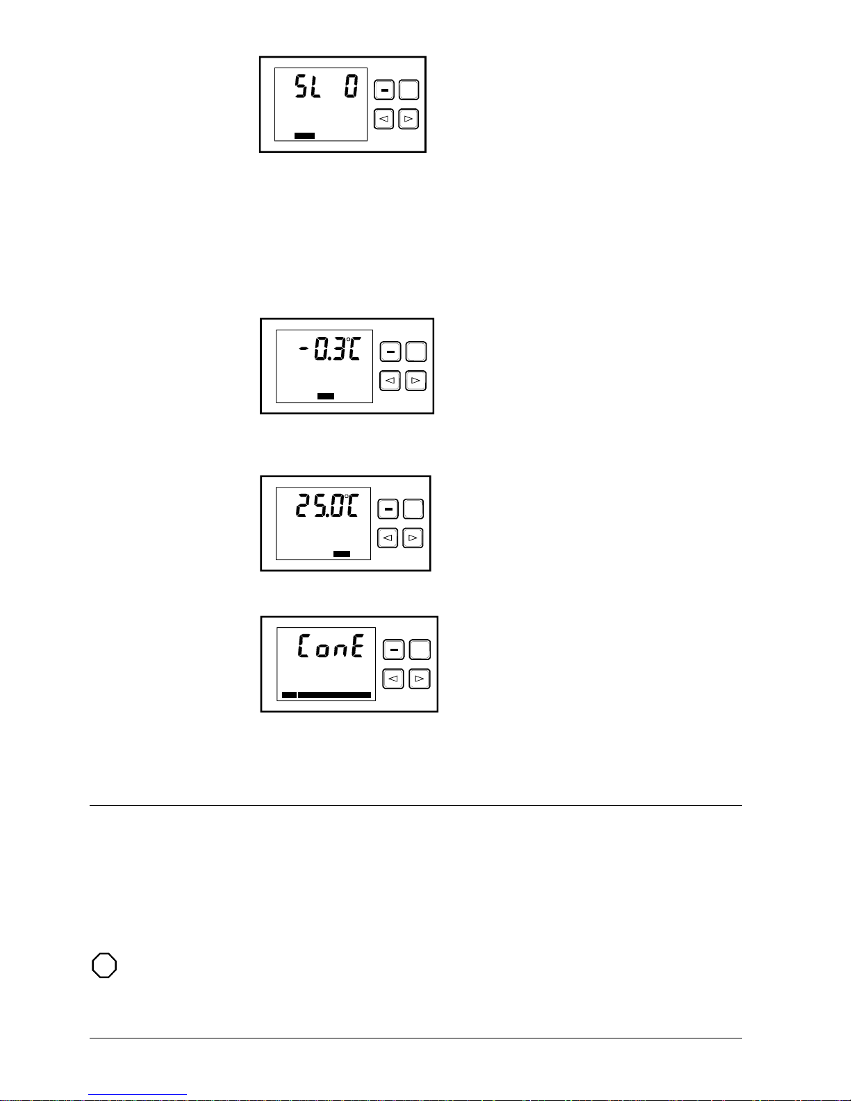
Slave On/Off
In a control loop with several room units, the temperature is measured in one device
only (the master). The LS flag (SL = 0) determines whether the room unit should
measure the temperature, or whether it is a slave device (SL = 1), in which case the
temperature sensor is disabled.
The default setting is SL = 0, i.e. temperature measurement active.
Further control loops can also be defined by means of a special application in the room
controller. In such cases, other room units can measure the temperature on the same
room bus.
Note
+
6320Z06
Offset correction
The error in an NTC 10 kΩ room sensor error combined with a measurement error
results in an error in the measured temperature reading. This can be corrected by
setting an offset correction value.
+
6320Z07
Measured temperature
This menu displays the current measured temperature including the previously set
offset correction value.
+
6320Z08
LCD display contrast
The LCD display contrast can be adjusted in this menu to suit different lighting
conditions.
Mounting instructions
To measure the temperature with the built-in temperature sensor, the HTC3.2/.. room
operator unit must be installed in a location suitable for room temperature
measurement.
Mounting location
This restriction does not apply if the temperature is measured with an external
temperature sensor. A suitable temperature sensor for this unit is the HSE1.1 cable
temperature sensor. If the VIMAR idea installation system is used, the room
temperature sensor HSE1.2 is also suitable.
STOP
Important note
Heat sources result in false temperature measurements. Ensure a minimum distance of
1.5 m from lamps.
6/10
Building Technologies HTC3.2/.. - Room operator unit CM2N6320en
01.09.2008
Page 7

If the sensor is in an unsuitable location, the measured value can be corrected with a
temperature offset. The correction can be undertaken with the SCOPE or HSC (Hotel
Solution Commissioning) tool.
Correcting the
measured value
In the standard application the basic setting for the temperature offset is –4 K. This
applies to the room operator unit in cases where the temperature is measured with the
internal room sensor.
If a type HSE1.2 external sensor is used for temperature measurement, a temperature
offset of – 1K must be set.
• The HTC3.2/.. room operator unit should be mounted at eye level in the living area
of the hotel room.
• Lamps and other heat sources in the vicinity of the room temperature sensor must
not be allowed to distort the measured temperature. The room unit with the built-in
temperature sensor is not suitable for mounting within reach of the bed, for example,
because items such as bedside lamps cause too great an increase in the measured
temperature.
• Conduits must be sealed where they enter wall boxes, so that the temperature is not
falsified by draughts.
• To remove the device, it must be unscrewed from the wall together with the baseframe.
• The screw terminals of the room operating unit can accommodate only one wire, with
a maximum diameter of 1 mm. When connecting the bus, therefore, we recommend
that the room unit should be connected as the last room-bus device.
• The device is intended for fixed installation in a dry, enclosed space.
• For installation in a 3-module mounting box, depth 50 mm
• Must be mounted horizontally only, with the front plate vertical
• Do not install AC 230 V devices in the same mounting box
• Commissioning must be carried out by trained personnel only
• Do not open the unit
• Local safety and installation regulations must be observed
Commissioning
To operate several devices connected to the same room controller, an address must be
set for each one (refer to "Engineering notes"). Only one device operates with the
factory-set defaults.
In the standard application with only one room unit, the defaults are ADR0=0, ADR1=0
and IE=1(internal sensor active). These are the factory-set values for the room operator
unit.
Note
Measured value corrections are carried out via the configuration menu or the SCOPE
or HSC tool, depending on where the sensors are located.
7/10
Building Technologies HTC3.2/.. - Room operator unit CM2N6320en
01.09.2008
Page 8

Operating notes
Pattern Description
All symbols OFF
No supply voltage to the HTC3.2
Possible causes:
− Room controller off or faulty
− Bus cable not correctly connected, or connection broken
− HTC3.2 faulty
All symbols
flashing (2 Hz)
No communication with the room controller
Possible causes:
− Wrong bus address set on HTC3.2
− Wrong bus address set in room controller
− Bus cable not correctly connected, or connection broken
− Room controller in "Stop" mode
− Faulty RS485 interface
Alarm messages
Technical data
Operating voltage DC 9..0.15 V
Power supply (from HRC3..)
Current 20 mA
Bus interface Bus voltage SELV DC 12 V
Type RS485
Transmission speed 4800 baud
Temperature signal input Measuring range 5 … 45 °C
Measuring current
1 mA
Measuring element NTC 10 kΩ
Setpoint correction Correction range ± 2 or ± 4 K
Resolution 0.5 K or 1 K
Parameter setting Parameters set with internal software and
stored in EEPROM
Ambient conditions Operating temperature 0...+ 50 °C
Transport temperature
-25..+ 65 °C
Humidity <95 % non-condensing
Air pressure during operation Min. 700 hPa (3000 m above sea level)
Air pressure during transport Min. 260 hPa (10 000 m above sea
level)
Industry standards
Product safety
Automatic electrical controls for household
and similar use
EN 60 730-1
Electromagnetic
compatibility
Emitted interference in accordance with
Interference immunity in accordance with
EN 61000-6-3
EN 61000-6-2
Housing
protection standard
To EN 60,529
IP20
Protection class To IEC1140 III
conformity Meets the requirements of:
EMC Directive
89/336/EEC
Low-voltage directive 73/23/EEC
Environmental
compatibility
Environmental product declaration
CM2E6320en provides data on
environmentally compatible product design
and assessment (material composition,
packaging, disposal)
ISO 14001 (environment)
ISO 9001 (quality)
UL/CUL approval UL/CUL 916
8/10
Building Technologies HTC3.2/.. - Room operator unit CM2N6320en
01.09.2008
Page 9
Installation Suitable for flush mounting in rectangular
flush-mounting box or rounded hollow wall
box
HTC3.2/BB and HTC3.2/BW
HTC3.2/VB and HTC3.2/VW
3 modules
Bticino 503E (angular),PS563N (round)
Vimar V71613 (round), V71304
(angular)
Color Operator panel Pantone black 7U2Y
Dimensions
HTC3.2/BB – Bticino frame L4703
HTC3.2/BW – Bticino frame N4703
HTC3.2/VB – Vimar frame 16713
HTC3.2/VW – Vimar frame 20613
(without cover; and see dimension
diagrams)
115 mm x 72 mm x 25 mm
114 mm x 72 mm x 25 mm
118 mm x 75 mm x 26 mm
118 mm x 75 mm x 26 mm
Weight
Excluding packaging
With packaging
0.066 kg
0.084 kg
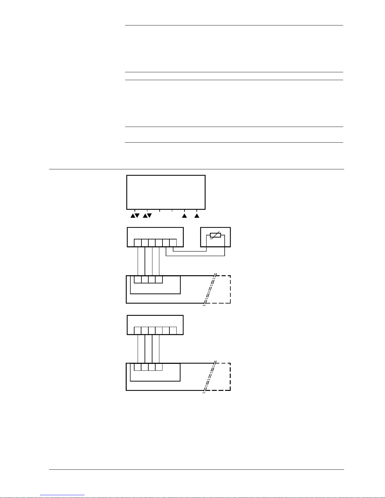
Connection diagrams
1 Serial port, RS485+
2 Serial port, RS-485 –
3 DC 12 V operating voltage
12 3456
(GND)
(DC 12 V)
6320G01
4 DC 0 V operating voltage
Connection terminals
S2
HTC3.2 room operator unit
(external temperature sensor)
B1 Temperature sensor
10 kΩ NTC
(e.g. HSE1.1, HSE1.2)
1 23456
1
234
S2 B1
N1
X12
6320A01
N1 HRC3.1 room controller
Connection diagram
HTC3.2 – external
temperature sensor
S2
HTC3.2 room operator unit
(internal temperature sensor)
1 23456
1
234
S2
N1
X3
6320A02
N1 HRC3.2 room controller
Connection diagram
HTC3.2 – internal
temperature sensor
9/10
Building Technologies HTC3.2/.. - Room operator unit CM2N6320en
01.09.2008
Page 10
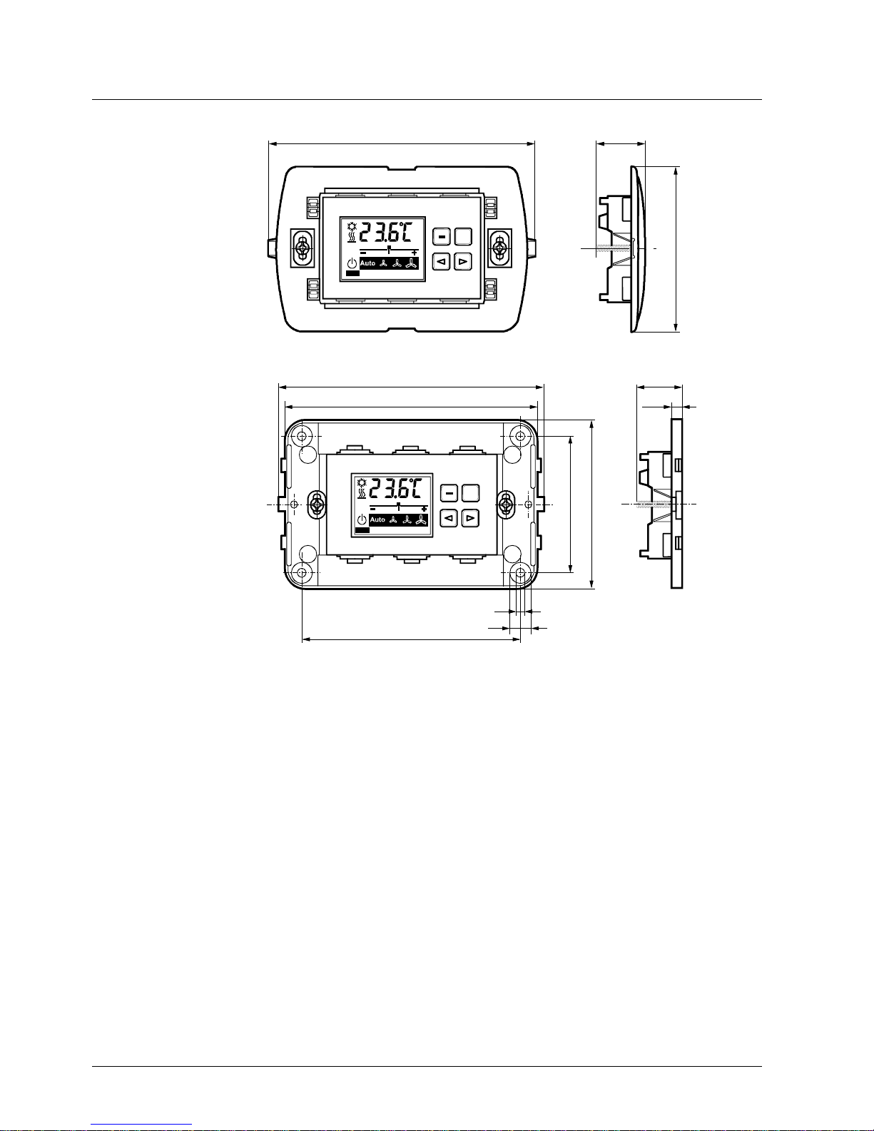
Dimensions
HTC3.2/BB
Diagram and dimensions of Bticino frame L4703.
115
72
6320M01
+
25
Dimensions in mm
HTC3.2/VB
Diagram and dimensions of Vimar frame 16713.
+
111,8
118
67
4
9
90,6
75
26
0,9
6320M02
Dimensions in mm
Note
See the frame supplier documentation for dimensions of other frames and hole spacing
(Bticino, Vimar).
10/10
Building Technologies HTC3.2/.. - Room operator unit CM2N6320en
© 2006-2008 Siemens Switzerland Ltd Subject to change
01.09.2008
 Loading...