

Page 1
Installation Instructions
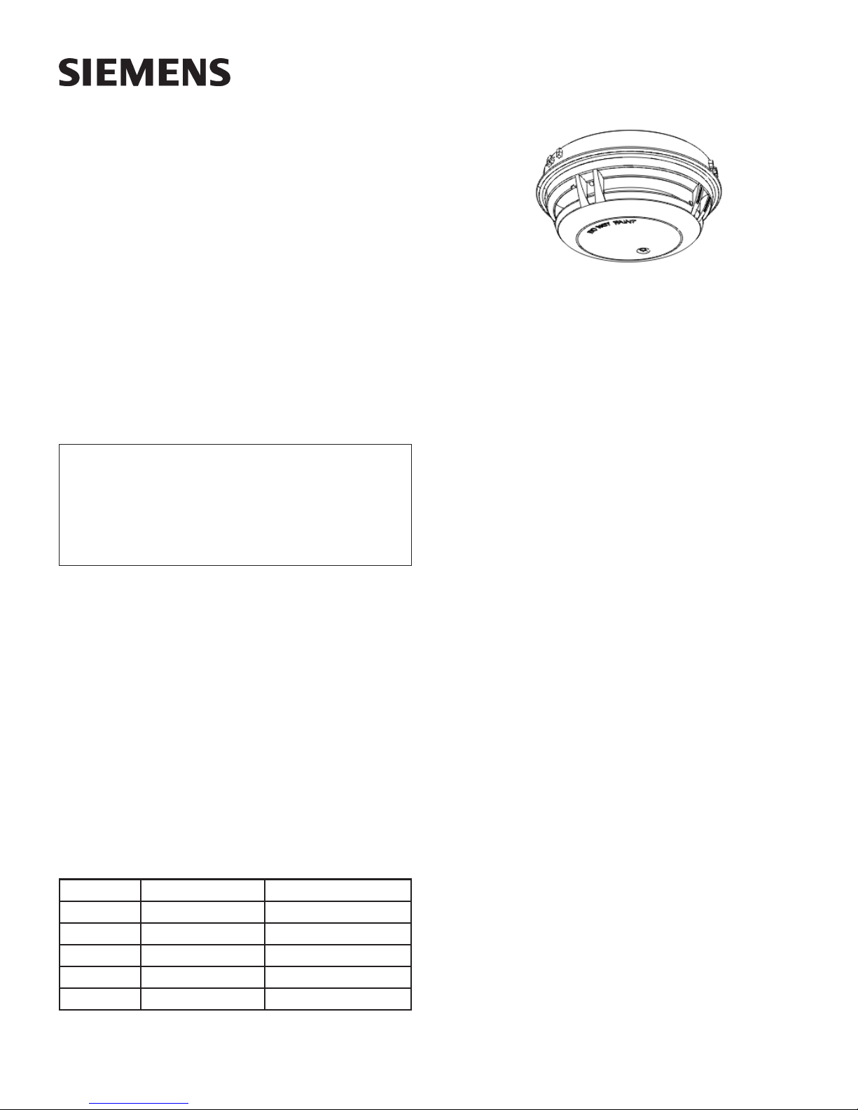
Model FDOOTC441
Multi-Criteria Fire/CO Detector
Figure 1
FDOOTC441
These instructions are written in accordance with the installation
guidelines of NFPA 72, National Fire Alarm Code. The model
FDOOTC441 detector (shown in Figure 1) meets the VEWFD
(Very Early W arning Fire Detector) classification and sensitivity
requirements of NFPA 76 (Standard for the Fire Protection of
Telecommunications Facilities) incorporating a programmable
“Alert” (Pre-Alarm) sensitivity threshold of 0.2%/ft obscuration
and an “Alarm” sensitivity threshold of 1.0%/ft obscuration.
CAUTION
Detection Device Storage
DO NOT install this detection device until all construction
is completed.
DO NOT store this detection device where it can be
contaminated by dirt, dust, or humidity.
DETECTOR PLACEMENT
Although no specific spacings are set for the detectors used for
a clean air application, for multi-criteria fire detection use 30
foot center spacing (900 sq ft) from NFP A S t andard 72 initiating
devices chapter, if practical, as a guide or starting point for a
detector installation layout. This spacing, however, is based on
ideal conditions–smooth ceiling, no air movement, and no
physical obstructions. In some applications, therefore,
considerably less area is protected adequately by each smoke
detector. This is why it is mandatory to closely follow the
installation drawings. In all installations place the detector on
the ceiling, a minimum of 6 inches from a side wall, or on a wall,
12 inches from the ceiling. For CO gas detection applications,
follow detector installation requirements in NFP A 720, S tandard
for Installation of Carbon Monoxide Detection and Warning
Equipment.
For FM Approved installations, this device has an R TI rating of QUICK.
For thermal detection, use the matrix below:
teeF,gnicapS,gnitaRerutarepmeT
05571,561,551,541,531drauGtuohtiWdnahtiW
06571,561,551,541,531drauGtuohtiW
06551,541,5
07541,531drauGtuohtiW
07531drauGhtiW
31drauGhtiW
0
FledoMdrauGtuohtiW/htiW
If you have any questions regarding detector placement, follow
the drawings provided or approved by Siemens Industry, Inc.,
or by its authorized distributors. This is extremely important! The
detector placements shown on these drawings were chosen after
a careful evaluation of the area that is protected. Such factors
as air currents, temperature, humidity , pressure, and the nature
of the fire load were carefully considered. Especially noted were
the room or area configuration and the type of ceiling (sloped or
flat, smooth or beamed). Siemens Industry, Inc.’s extensive
experience in the design of the system assures the best detector
placement by following these drawings.
TO AVOID NUISANCE ALARMS
Do not locate the detectors where excessive smoke
concentrations exist under normal conditions, or in areas of
prolonged high relative humidity where condensation occurs.
Do not locate the detectors next to an oil burner, kitchen, or
garage where exhaust fumes can trigger an alarm. Other causes
of false alarm are dust accumulation, heavy concentrations of
steam, heavy pipe or cigar smoke, and certain aerosol sprays.
AIR CURRENTS
Before a detector can sense a fire, the products of combustion
or smoke must travel from the fire to the detector. This travel is
especially influenced by air currents; therefore, consider air
movement when designing the system. While combustion
products tend to rise, drafts from hallways, air diffusers, fans,
etc., may help or hinder the travel of combustion products to the
detector. When positioning a detector at a particular location,
give consideration to windows and doors, both open and closed,
to ventilating systems, both in and out of operation, and to other
factors influencing air movement. Do not install a detector in the
air stream of a room air supply diffuser. It is better to position a
detector closer to an air return.
The distance that products of combustion or smoke travel from
a fire to the detector is not usually the shortest linear route.
Combustion products or smoke usually rise to the ceiling, then
spread out. Average ceiling heights of 8 to 10 feet do not
abnormally affect detector response. High ceilings, located in
churches, warehouses, auditoriums, etc., do affect detector
response and should be considered.
SPECIAL CEILING CONSTRUCTION FACTORS
Ceiling obstructions change the natural movement of air and
combustion products. Depending on the direction of smoke
travel, joists and beams can slow the movement of heated air
A6V10324657_en--_f
Building Building
Building
Building Building
Siemens Siemens
Siemens
Siemens Siemens
TT
ecec
hnologies Dihnologies Di
T
ec
hnologies Di
TT
ecec
hnologies Dihnologies Di
IndustryIndustry
Industry
IndustryIndustry
visionvision
vision
visionvision
,,
Inc. Inc.
,
Inc.
,,
Inc. Inc.
Page 2

and smoke, while pockets between them can contain a reduced
level of smoke. Take obstructions created by girders, joists,
beams, air conditioning ducts, or architectural design into
consideration when determining area protection. Refer to the
Initiating Devices chapter of NFPA S tandard 72 for Location and
Spacing requirements for specific types of construction; e.g.
beam, suspended, level, sloped and peaked ceilings.
(UL268A), heat (UL521) and CO (UL2075) which can be used
simultaneously and can be configured and switched on or off
individually by the panel. Follow the description and instructions
provided in the operation manual of specific control panel used.
The FDOOTC441 can be set to the FDOOTC441 Selectable
Application Profiles, FDOOTC441 Selectable Fixed Temperature
Threshold Profiles and the FDOOTC441 Selectable Alarm
Threshold Setting Profiles shown in the tables below and to the
TEMPERA TURE – HUMIDITY – PRESSURE – AIR VELOCITY
The temperature range for the FDOOTC441 detector is 32°F
(0°C) to 120°F (49°C). Use the detector in environments where
the humidity is 15% to 95% RH continuous and 1% to 99% for
short duration (24h to 48h). Normal changes of atmospheric
pressure do not affect detector sensitivity . The air velocity range
is 0-4000 ft/min for open areas applications. Follow detector
spacing and location requirements in NFP A 72 Chapter for High
Air Movement Areas and Control of Smoke Spread. The
right.
Additionally the detector can have another channel that can be
configured by the panel to have a low or high temperature
warning in the range from -4° to 120°F (-20° to 49°C). (Not with
FC2005.)
Additionally the detector can be configured by the panel to have
a CO gas concentration warning in the range of 30-600ppm.
(Not with FC2005.)
detectors can also be installed in duct applications between 0
and 4000 ft/min. For duct installations follow detector installation
requirements in NFPA 90A, Chapter for Special Ceiling
Construction Factors. When the detectors employ a fixed
temperature rating of 165
0
F or less, they are intended for a
maximum installation temperature of 1000F (37.80C).
UL listed with STI Mechanical Protection Guard Model: STI-9604
(see www.STI-USA.com for details).
LED INDICATOR OPERATION
The Model FDOOTC441 contains an LED indicator capable of
flashing either one of three distinct colors: green, yellow, or red.
During each flash interval, the microprocessor-based detector
monitors the following:
• Smoke in its sensing chamber
• Smoke sensitivity is within the range indicated on the
nameplate label
• Internal sensors and electronics
Based on the results of the monitoring, the LED indicator flashes
the following:
hsalF
roloCnoitidnoC
*neerG
wolleY
deRmralA1
oN
*sehsalF
vitisnes
.tnemecalper
tceteD
.dedeensi
.desulenaPeht
ekomS.noitarepoyrosivrepuslamroN
.stimildetarnihtiwsiyti
sdeendnaelbuortnisirotceteD
tnemecalperro,derewoptonsiro
lavretnIhsalF
)sdnoceS(
01
4
fonoitpircsedgnidnopserrocehtwollofesaelP.ffodenrutebnacDEL*
DETECTOR PROGRAMMING
Each detector must be programmed to respond to a unique
system address between 001 - 050 for FC2005.
• To program the detector address, use the Model DPU
Device Programming Unit. Refer to the DPU Manual, P/N
315-033260.
• Record the loop and device number (system address) for
the detector on the detector label and on the base to
prevent installing the detector in the wrong base. The
optional DPU label printer can be used for this purpose.
Each detector provides pre-programmed parameter sets which
can be selected by the panel. The FDOOTC441 provides three
different alarm channels: multi-criteria (UL268) and direct in-duct
Siemens Industry, Inc.
Building Technologies Division
ELECTRICAL
For information on electrical characteristics of the detector, refer to
the FDOOT441/FDOOTC441 T echnical Manual, A6V10325549 at
https://www.buildingtechnologies.siemens.com/extranet/ba-sp/.
Refer to the panel Installation, Operation and Maintenance
Manual for maximum line impedance of the loop driver.
WIRING
Detector bases for Model FDOOTC441 should be connected
as shown in Figure 2.
DETECTOR MOUNTING
The recommended orientation of the detector for wall mounting
is shown in Figure 3. T o ensure proper inst allation of the detector
head into the base, be sure the wires are properly dressed at
installation:
• Position all wires flat against the base.
• Take up all slack in the outlet box
• Route wires away from connector terminals.
TO INSTALL DETECTOR HEAD:
• Rotate detector counterclockwise while gently pressing on
it until the detector seats fully into base.
• Then rotate the detector clockwise until it stops and locks in
place. Insert optional locking screw (Order Model LK-11).
TO REMOVE DETECTOR HEAD:
• Loosen locking screw, if installed. Then rot ate the detector
counterclockwise until stop is reached.
• Pull detector out of base.
erutarepmeTdexiFelbatceleS144CTOODF
seliforPdlohserhT
0
531erutarepmetdexiF
F
0
F
541erutarepmetdexiF
0
F
551erutarepmetdexiF
0
F
561erutarepmetdexiF
0
F
0
531erutarepmetdexiF
0
571erutarepmetdexiF
0
531erutarepmetdexiF
0
571erutarepmetdexiF
571erutarepmetdexiF
0
51)RoR(esiRfoetaR+F
F
0
51)RoR(esiRfoetaR+F
F
0
02)RoR(esiRfoetaR+F
F
0
02)RoR(esiRfoetaR+F
F
seliforPgnitteSdlohserhTmralAelbatceleS144CTOODF
dlohserhTtf/%05.2
dlohserhTtf/%00.3
f/%05.2
deifirev,dlohserhTt
deifirev,dlohserhTtf/%00.3
A6V10324657_en--_f2
Page 3

seliforPnoitacilppAelbatceleS144CTOODF
noitacinummoceleT tnempiuqegnissecorplangiseulavhgih,detalugeryl
eriFemitnwodtneverpotmralA-erP)DFWEV(noitceteD .ytiunitnocssenisublacitircniatnia
tneipicnI .mralanoitcetedgninrawylraesedivorP.detalugerylesolcerutarepmet,naelc,tnemnorivnedellort
tnelaviuqenoI .selcitraperutangiserifllamsdnaserifgnimalfotevitisneS.rotcetednoitazinoIotevitan
nocyreV
retlanasadesU
esolcerutarepmet,naelc,tnemnorivnedellortnocyreV
mdna
.stnemeriuqernoisserppusgninozssorcrofdesuebnaC
retneCataD netfo,yticolevriahgih,tnempiuqe
ocleTrodnaelbac,gnissecorpatadgniniatnoctnemnorivnedellortnoC
.sroolf-bussniatnoc
mooRretupmoC gnissecor
.snoitidnocyticolevriahgihdnagnitarepotnempiuqe
egarotSsuoicerP .derisedgninrawtseilrae,tnemnorivneeerf-tsudnaelc,egarotstn
noitareneGrewoP emoS.tneserpgnicralacirtcele,gnidlew,FR,gniwserutarepmetonro
empiuqeroslairetamevtisneS
ronim,tnemnorivnedellortnoC
.tneserptnanimatnoc)anemonehpevitpeced(enrobria
latipsoH oterusopxE.tnempiuq
egnitarenegFRerusopxeemoS.ksirlevelhgiH.tnemnorivnenaelcdellortnoC
.stnevlosgninaelc
eraChtlaeH .erusopx
yrotimroD .maetsdnagn
mooRytilitU .tnempiuqegninnurmorfta
ybboL .etalucitrapedistuoemos,senohpralullec,segnah
cerutarepmet,aeranaelcylevitaleR
eh,tnemnorivneytridtahwemosotlamron,moorremrofsnarT
ikoms,semufgnikooC.sretrauqgnivil,segnahcerutarepmetdnatsudenrobriA
eciffO.erehpsomtadellortnocetamilc,naelcylbanosaeR
letoH .elbissopgnikoo
loohcS .stnanimatnocenrobriadnasgniwserutarepmetemos
,ytefasefiL
cdnagnikoms,maets,sgniwserutarepmetemos,ytefasefiL
esuoheraW .semuftsuahxednaaerakcodmuidemotthgildnatfilkrof,tnempiuqe,tsudenrobriA
naMedulcninactnemnorivnedellortnoc-imeS stnanimatnocenrobria,gnidlew,gniredloslacimehcgnidulcni
gnirutcafu
.erusopxeropav
egaraGgnikraP .sgniwserutarepmetegral,semufleseiddnaraC.tsudenrobriA
tnemnorivnEnepO semufmorfanemo
.elbissop
esionIME latnemnorivner
.lamronerasnoitidnoc
el
itsoH .sgniwserutarepmetediw,tneserpFR,tnempiuqegnitarepo,dimuh,ytsud,ytriD
OC/wretneCataD netfo,yticole
.sroolf-bussniatnoc
OC/
wletoH gnikoms,maets,sgniwserutarepmetemos,ecnadiovamralaecnasiungnitroppusrosnesOCsedivorP
.elbissopgnikoocdna
OC/welitsoH .anemonehpevitpecedmorfsmralaecnasiungnidiovarofnoitcetedekomstsuborotrosnesOCsddA
.sgniwserutarepmetediw,tneserpFR,tnempiuqegnitarepo,dimuh,ytsud,ytriD
OC/wtcuD .sgniwserutarepmetediw,d
imuh,ytsud,ytrid,yticolevriahgiH.troppusOChtiwtcudninoitcetedekomS
fostnemeriuqernoitcetedehtsteeM.sgniliechgihsahnetfO.snoitidnocyticolevriahgihdnagnitarepo
gninraWylraEyreVagnidivorpybtnempiuqEnoitacinummoceleTfonoitcetorPehtrofdradnatS67APFN
plangisnaelceulavhgih,detalugerylesolcerutarepmet,naelc,tnemnorivnedellortnocyreV
eropavgninaelcdnalacimehcemoS.tnempiuqecinortcele,naelcylevitaler,ksirlevelrehgiH
nehpevitpeced,sgniwserutarepmeT.smuidats,sanera,smuirta,saeranepoegraL
ehtO.langislacirtcelegnitarenegtnempiuqedezilaicepsruodnaFR,ecafretnilacirtcelE
vriahgih,tnempiuqeocleTrodnaelbac,gnissecorpatadgniniatnoctnemnorivnedellortnoC
*1SUdecnalaB dna4302LUmorfstnemeriuqerytivitisnesslliflufdna5702LUsteemtesret
.1-91.6ASC
5002CFhtiwdesutoN*
DETECTOR TESTING
Only qualified service personnel should test. To assure proper
operation of the detector, both the Sensitivity and Functional
Test should be conducted. The minimum test schedule may be
found in the current edition of NFPA 72.
The CO sensor of the FDOOTC441 has a 5-year lifetime from
the date of installation.
Siemens Industry, Inc.
Building Technologies Division
eliforPytefaSefiLOCCTOODF
emarap1SUdecnalaBehT
SENSITIVITY MEASUREMENT
The sensitivity of FDOOTC441 detectors can be tested
individually using the DPU. Refer to the DPU Manual, P/N 315-
033260. The sensitivity can be measured by the panel. Follow
the instructions of the panel used.
A6V10324657_en--_f3
Page 4

T
LINE 1**
T
TO INITIATING
CIRCUIT OF
SIEMENS
INDUSTRY,INC.
COMPATIBLE
CONTROL UNIT
LINE 2**
Figure 2
Installation and Wiring Diagram
TB1
TB2
TB3
REMOTE RELAY
BASE MODEL DB2-HR***
5
NO
C
6
NC
RELAY*
CONTACTS
3A, 120 VAC
3A, 30 VDC
561a
1b
DETECTOR BASE
MODEL DB-11/DB-11E
561a
SUPERVISED AND POWER LIMITED
*The relay contacts are shown after System reset, which represents the non-alarm condition.
**FDOOTC441 is a polarity insensitive detector. Line 1 and Line 2 can be either line of the loop.
***FDOOTC441 is NOT compatible with the DB-HR base.
1b
OPTIONAL
REMOTE
ALARM
INDICATOR
MODELS
RL-HW/RL-HC
TO NEXT BASE
5
NO
C
6
NC
TO NEXT BASE
DO NO
USE AN
END OF
LINE
DEVICE
DO NO
USE AN
END OF
LINE
DEVICE
Figure 3
1.
MOUNT BOX ON
WALL WITH
EXTERIOR
MOUNTING HOLES
IN UPPER LEFT
AND LOWER
RIGHT POSITIONS
WALL
4-INCH SQUARE BOX
2 1/8-INCHES DEEP
DB-11 BASE
LOCKING HOLE
2.
D
O
N
O
T
P
A
I
N
T
MOUNT DETECTOR
BASE TO 4-INCH
SQUARE BOX AS
SHOWN WITH
LOCKING HOLE
ON LEFT TOP IN
POSITION SHOWN
Recommended Detector Wall Mounting / Detector Guard Orientation
SMOKE DETECTOR FUNCTIONAL TEST (SMOKE TEST GAS)
The fire control panel
must be programmed to test mode prior
to performing a functional (*Go-No-Go) smoke entry test. Failure
to do so may result in a test failure. Refer to the specific control
panel installation operations manual for proper “test mode”
programming instructions. To determine how to put the control
panel in “test mode”, specific programming instructions are
located in the following documents: XLS IOM, P/N 315-033744,
FC2005 Installation Instructions, P/N A6V10333722, and
FC2025/FC2050 Installation Instructions, P/N A6V10315023. T o
activate the detector with test gas, only use SmokeCheck™ test
gas manufactured by HSI Fire & Safety Group, P/N HO-25S
(see www.homesafeguard.com for product and ordering details).
Strictly follow the testing instructions provided on the gas
canister label.
After applying the test gas for 1-2 seconds, the
smoke alarm will occur within 4-10 seconds. If not, check the
Test Mode and repeat the test. Do not repeat the test multiple
times or apply the test gas too long – this will cause CO-troubles.
CAUTION: DO NOT USE AT DISTANCES SMALLER THAN 2
FEET (0.6m) FROM DETECTOR. SPRA Y THE TEST GAS FOR
A PERIOD OF 1-2 SECONDS. EXCESSIVE SPRAYING MAY
AFFECT THE DETECTOR’S SENSITIVITY AND CAUSE CO
SENSOR TROUBLES.
*This test is simply used to ensure that smoke can enter the
sensing chamber and alarm the control panel when the detector
reaches the programmed obscuration (concentration) level.
CAUTION: DO NOT USE ANY TEST GAS OTHER THAN THE
ONE MENTIONED ABOVE AS COMPATIBILITY TO THE CO
SENSOR CANNOT BE ASSURED.
Test by activating the detector using the approved CO test gas,
Siemens P/N 500-650053, following the instructions with product
and provided on the CO gas canister label. Spray the CO gas
stream into the detector opening from the opposite side of the
alarm indicator LED
from the CO sensor to the straw of the test gas can is required.
Use only short (approx. 1-2 seconds, BUT NOT LONGER THAN
2 seconds) activation of the gas can. Af ter applying the test gas
for 1-2s, the CO alarm will occur within 4-10 seconds. If not
please check the Test Mode again and repeat the test. Do not
repeat the test multiple times or apply the test gas too long –
this will cause CO-troubles.
*This test is simply used to ensure that a CO gas can enter the
sensing chamber and alarm the control panel when the detector
reaches the programmed obscuration (concentration) level.
The FDOOTC441 detectors can also be tested individually using
the DPU. Refer to the DPU manual, P/N 315-033260.
MAINTENANCE
The control unit automatically indicates the trouble message for
the FDOOTC441 detector whose smoke chamber changes to
the level where the set sensitivity cannot be maintained. In such
circumstances, the detector may require replacement.
CAUTION: UNDER NO CIRCUMSTANCES IS THE DETECTOR HEAD
TO BE DISASSEMBLED. NO REPAIRS SHOULD BE ATTEMPTED.
DO NOT PAINT
The detector/base plastic is marked DO NOT PAINT. This is
intended to prohibit painting during routine maintenance of the
occupancy which can affect proper operation of the detector.
CO DETECTOR FUNCTIONAL TEST (CO TEST GAS)
The fire control panel must be programmed to test mode prior
to performing a functional (*Go-No-Go) CO gas entry test. Failure
to do so may result in test failure. Refer to the specific control
panel installation operations manual for proper “test mode”
programming instructions. To determine how to put the control
panel in “test mode”, specific programming instructions are
located in the following documents; XLS IOM, P/N 315-033744,
FC2005 Installation Instructions, P/N A6V10333722, and
FC2025/FC2050 Installation Instructions, P/N A6V10315023.
3.
WHEN 4-INCH SQUARE
BOX AND DETECTOR BASE
ARE MOUNTED AS SHOWN,
DETECTOR
DETECTOR LED WILL BE IN
RECOMMENDED 0 POSITION
WITH DETECTOR INSERTED
IN BASE.
STI-9604
WHEN MOUNTING THE STI-9604
MECHANICAL GUARD (BOTH
POSITIONS: WALL OR CEILING),
USE ORIENTATIONINDICATED IN
THIS DRAWING.
0
a distance of approximately 2 inches (5cm)
TNEMPIUQELORTNOCELBITAPMOC
reifitnedIytilibitapmoCtnempiuqEsnoitcurtsnIgniriW/noitallatsnI
2R-/2U-5002CF4
2R-/2U-5202CF83051301V6A
2R-/2U-0502CF83051301V6A
)CLD(SLX-redniFeriF090330-513
2733301V6A
.reifitnediytilibitapmocehtsirebmunledomrotcetedehT
Siemens Industry, Inc.
8 Fernwood Road
Building Technologies Division
Florham Park, NJ 07932
Siemens Canada Limited
Building Technologies Division
2 Kenview Boulevard
Brampton, Ontario L6T 5E4 Canada
P/N A5Q00044197
Document ID A6V10324657_en--_f
 Loading...