

Siemens FDCIO223, FDCH221 Installation Manual
Building Technologies
009124 Fire Safety & Security Products
FDCIO223 FDCH221
en Input/output module (Transponder) Housing
de Ein-/Ausgabebaustein (Transponder) Gehäuse
fr Interface d'entrées/sorties (transpondeur) Boîtier
es Módulo de entrada/salida (transpondedor) Carcasa
it Modulo in/out digitali (Transponder) Contenitore
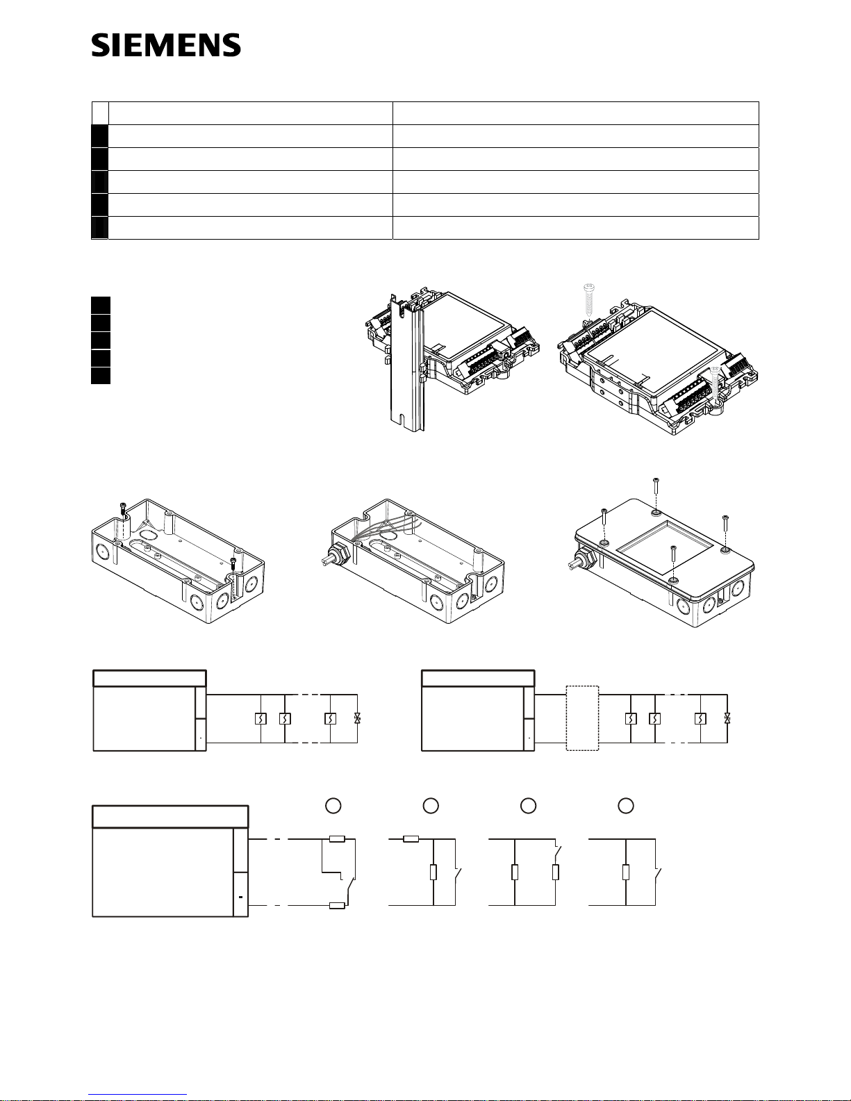
en Installation
de Montage
fr Montage
es Montaje
it Montaggio
Fig. 1 Fig. 2
Fig. 3 Fig. 4
Fig. 5
+
I/O
FDCIO223
EOL
+
I/O
FDCIO223
SB3
EOL22 (ex)
Fig. 6 Fig. 7
+
I/O
FDCIO223
2k7
560
3k3 680
560
2k7
3k3
1 2 3 4
Fig. 8

2
Building Technologies 009124_d_--_-Fire Safety & Security Products 12.2009
24 V
0 V
0 V
3 V
RL = 30 ... 3k3
I/O
FDCIO223
+
2 AT
10 V
0 V
3k3
I/O
FDCIO223
24 V
0 V
+
2 AT
Fig. 9 Fig. 10
Fig. 11
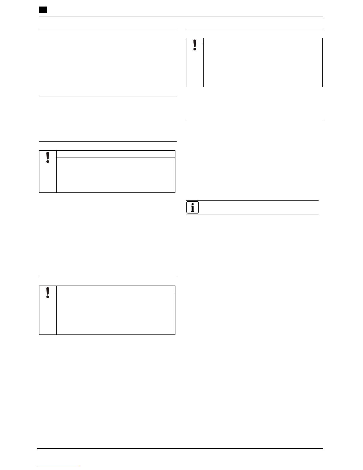
en Legend es Leyenda
Fig. 6 Detector line Fig. 6 Línea de detectores
Fig. 7 Detector line with safety barrier (Ex Zone 1+2) Fig. 7 Línea de detectores con barrera de seguridad (zona Ex
1+2)
Fig. 8 Contact inputs
1 … 3 = monitoring for short-circuit and open line
4 = monitoring for open line
Fig. 8 Entradas de contacto:
1 … 3 = Monitorización en cuanto a cortocircuito y circuito
abierto
4 = Monitorización en cuanto a circuito abierto
Fig. 9 Control output with equality polarity monitoring Fig. 9 Línea de mando con monitorización de la misma polaridad
Fig. 10 Control output with reversed polarity monitoring Fig. 10 Línea de mando con monitorización de polaridad inversa
de Legende it Leggenda
Fig. 6 Melderlinie Fig. 6 Linea di rivelatori
Fig. 7 Melderlinie mit Sicherheitsbarriere (Ex-Zone 1+2) Fig. 7 Linea di rivelatori con barriera di sicurezza (zona Ex 1+2)
Fig. 8 Kontakteingänge:
1 … 3 = Überwachung auf Kurzschluss und Unterbruch
4 = Überwachung auf Unterbruch
Fig. 8 Ingressi contatti:
1 … 3 = monitoraggio per cortocircuiti e interruzioni
4 = monitoraggio per interruzione
Fig. 9 Steuerlinie mit gleichgepolter Überwachung Fig. 9 Linea di pilotaggio con monitoraggio dotato di polarità
uguale
Fig. 10 Steuerlinie mit gegenpoliger Überwachung Fig. 10 Linea di pilotaggio con monitoraggio dotato di polarità
opposta
fr Légende
Fig. 6 Ligne de détection
Fig. 7 Ligne de détection avec barrière à sécurité intrinsèque
(zone Ex 1+2)
Fig. 8 Entrées de contact :
1 à 3 = contrôle de court-circuit et d'interruption
4 = contrôle d'interruption
Fig. 9 Ligne de commande avec surveillance homopolaire
Fig. 10 Ligne de commande avec surveillance de pôles
opposés
3
Building Technologies 009124_d_--_-Fire Safety & Security Products 12.2009
en Installation
Intended use
The in/output module is operated on the FDnet/C-NET. It
has two inputs/outputs. These can be wired as follows:
– Collective detector lines
– Control lines
– Contact input
An optional housing is available to protect against
environmental influences such as wet or damp.
Installing the in/output module
The in/output module can be installed as follows:
– In the housing FDCH221 (Fig. 5)
– On a top hat rail (Fig. 1)
– On an even surface (Fig. 2)
Installation in housing
NOTICE
Module use in a damp, wet or dusty
environment
Damage to module from dust or jet of water
In damp, wet or dusty environments, fit the
module in a housing FDCH221.
1. Open the housing (Fig. 5).
2. Determine the cable entries in the housing and break
these open.
3. Use two screws to fit the housing on a plane surface
(Fig. 3).
4. Secure the M20 x 1.5 cable glands on the housing and
guide in the cables (Fig. 4).
5. Use two M3 x 12 screws to fit the module in the housing
(Fig. 2).
6. Close the housing with the screws provided (Fig. 5).
Procedure with installation on a top hat rail
NOTICE
High temperatures in the module's
environment
Module overheating and damage
A minimum clearance of 1 cm must be
observed between two modules or between
the module and any other boundary.
1. Place two mounting feet in the in/output module.
2. Press the in/output module with the mounting feet
against the top hat rail until it engages (Fig. 1).
Procedure with installation on an even surface
NOTICE
High temperatures in the module's
environment
Module overheating and damage
A minimum clearance of 1 cm must be
observed between two modules or between
the module and any other boundary.
1. Fix the in/output module with two screws on an even
surface (Fig. 2).
Electric connection
1. Connect the cables to the terminals according to the
connection diagram (Fig. 11). Connect only one wire
per terminal.
2. Every control line must be protected with a separate
fuse, with a rating of max. 1.5 or 2 AT.
3. Connect the monitoring resistors or line terminators
(EOL). These must be connected to the end of the line
(Fig. 6 … 10).
4. Connect the cables to the module with cable ties (max.
width 2.6 mm).
For additional information please refer to doc. no. 009122
 Loading...