

Siemens FDCIO181-2 Product Manual
FDCIO181-2 Input/Output Module
Product Manual
Characteristic
l Microprocessor-controlled signal evaluation
l Automatic address setting, without encoder settings or DIP switch
l 2 monitored input, 2 monitored output
l LED display of input and output status
l Input lines monitored for open line or short circuit
l Prevention of noise interference through intelligent analysis of input signals
l Output lines monitored for open line or short circuit (when potential output and not activated)
l Output monitoring configurable(on/off)
l Control output for equipment 24 VDC, max. 2 A
l Power supply via FD18-BUS
l Communication with controller via FD18-BUS(detector line)
l Directly used in dry areas. Applicable in dusty and humid areas when installed in housing
l “Sticker Method” easy for commissioning
Building Technologies
Fire safety and security products
1N5404
Application
Input
With the input a status can be monitored, the input can be configured by controller or
configuration tools as follows:
l “Status“ input or “Alarm“ input
l Lead monitoring for open line or open line and short circuit
l When inputting status, according to different status of contact, can be set as fallows:
– Normal mode: normally open NO input
– Inverted mode: normally closed NO input
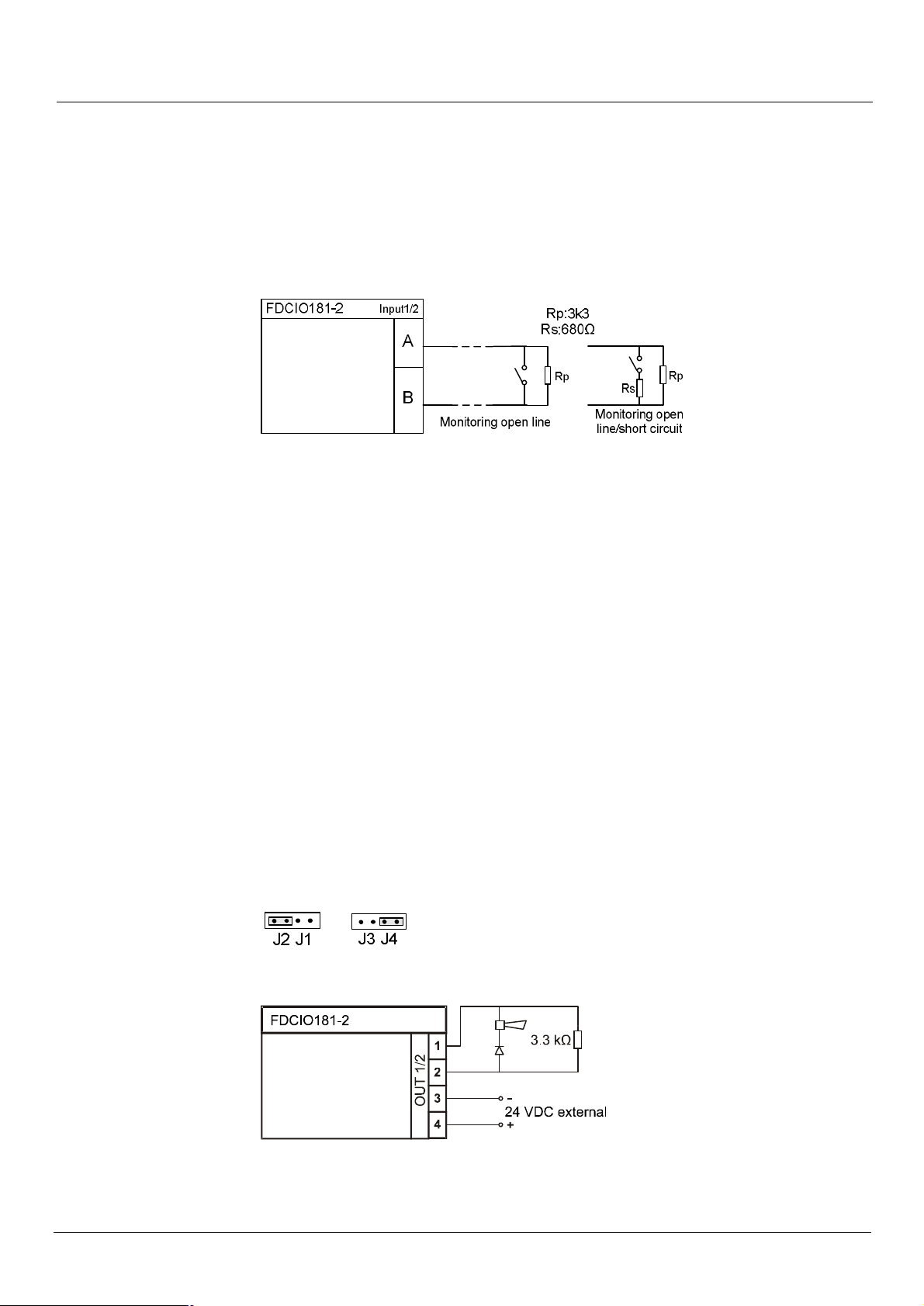
Fig. 1 connection diagram of dry contact input
Status” inputs and alarm” inputs
“Alarm“ inputs trigger an alarm as soon as the input is activated. “Status“ inputs trigger a
monitoring status change as soon as they are activated.
Line monitoring and circuitry
The input lines are monitored for open line or open line and short circuit. To make these
possible, resistors must be properly connected to the end of lines of the input (Fig. 1). When
an open line or a short circuit occurs on one of the input lines, a fault message is transmitted
to the control panel. The input must be potential-free.
Output
External power output (Default)
Normal operation (output lines monitored)
- Be used for controlling (e.g. operating a horn/strobe).
- The module switches the externally supplied 24 VDC voltage in active status on the
output.
- In inactive status the output line is monitored for open line and short circuit (Fig. 3).
- The jumper on the input/output module must be plugged onto J2/J4 (Fig. 2)
Fig.2 Input/output module jumper position J2, J4
Fig.3 Connection for normal operation with output line monitored for short circuit and open line
2
Building Technologies A6V10214492_a_en_--
Fire safety and security products 03.2010
Configuration
The following configurations are possible through controller or configuration tool:
l After activating the output remains:
‒ Steady output
‒ Pulse output: How long the contact remains active can be configured by controller or
configuration tools (pulse duration).
l Failsafe behavior when the FD18-BUS detector line is current-free or in degraded mode.
The error behavior defines the position of the output in case of an error:
‒ Off: Output remains in the same position as before the error
‒ Activation: Output is activated in case of an error
‒ Deactivation: Output is deactivated in case of an error
The controller does not monitor external equipment status (activated/inactivated).
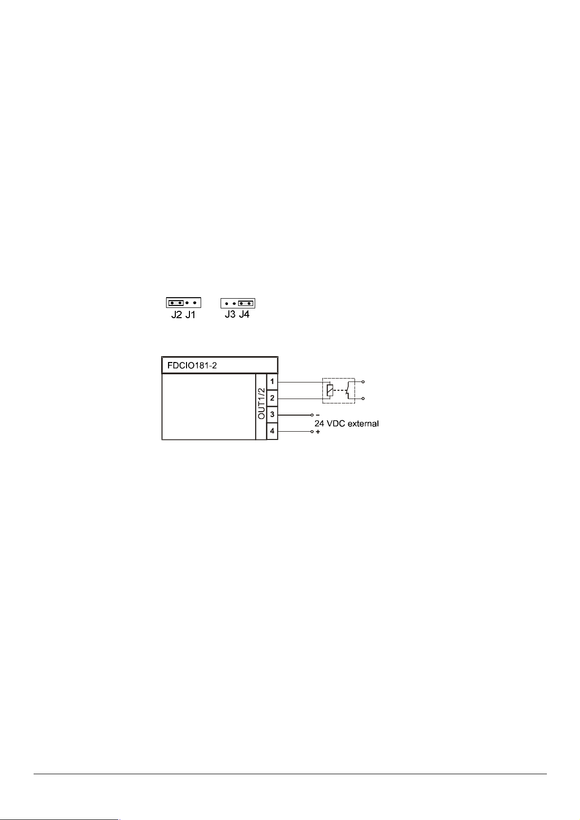
Inverted operation (output lines not monitored)
- Be used for controlling (e.g. closing a door).
- The module switches the externally supplied 24 V DC voltage in active status on the
output.
- In normal status there is no monitoring for open line and short circuit.
- The jumper on the input/output module must be plugged onto J2/J4 (Fig. 4).
Fig. 4 Input/output module jumper position J2, J4
Fig. 5 Connection diagram for inverted operation, e.g. when used as door retainer.
In inactive status the 24 V DC are permanently applied to the output and may keep a door
open, for example. When the output is switched to active, the output goes into "open" status
(= no 24 V DC voltage) and the door is closed.
Comment:
In this example, the door would also close if the 24 VDC supply were to fail, e.g. due to a line
problem (short circuit, open line).
Configuration
Under inverted mode, the following configurations are possible through controller or
configuration tools :
l After activating the output remains:
‒ Steady output
‒ Pulse output: How long the contact remains active can be configured by controller or
configuration tools (pulse duration).
l Failsafe behavior when the FD18-BUS detector line is current-free or in degraded mode.
The error behavior defines the position of the output through controller or configuration
tools in case of an error :
‒ Off: Output remains in the same position as before the error
‒ Activation: Output is activated in case of an error
‒ Deactivation: Output is deactivated in case of an error
The controller does not monitor external equipment status (activated/inactivated).
3
Building Technologies A6V10214492_a_en_--
Fire safety and security products 03.2010
 Loading...