

Page 1

Global Air Duct Monitoring Housing
Installat ion Instructions
Model FDBZ492-PR
INTRODUCTION Model FDBZ492-PR from Siemens Industry, Inc., is a RoHS
compliant air duct monitoring housing containing sampling
tubes. When used with a Siemens conventional smoke detector,
smoke and combustion products are detected for shutdown of
the duct system and/or operation of supplementary equipment
as provided by the system control panel. The duct unit supports
two sets of Form C alarm contacts, one Form A alarm contact
and one Form C trouble contact. The trouble contact supervises
the presence of the input power, removal of the detector cover
and the removal of the smoke detector head.
TECHNICAL DATA AIR DUCT CONDITIONS
Temperature Range:
With PE-11, 8854, PE-11C: 0
O
C (32OF) - 38OC (100OF)
With OP121: 0
O
C (32OF) - 49OC (120OF)
Altitude Range:
No altitude limitations
Relative Humidity:
Up to 95% RH (non-condensing/non-freezing)
Air Duct Velocity Range:
100-4000 ft/min
Sampling and Exhaust Tube Pressure Differential Range:
Greater than 0.01 and less than 1.2 inches of water column
These airThese air
These airThese air
These air
duct det duct det
duct det duct det
duct det
ectors are designed forectors are designed for
ectors are designed forectors are designed for
ectors are designed for
det det
det det
det
ectect
ectect
ect
ion andion and
ion andion and
ion and
control of products of combustcontrol of products of combust
control of products of combustcontrol of products of combust
control of products of combust
ion in a duct syion in a duct sy
ion in a duct syion in a duct sy
ion in a duct sy
stst
stst
st
em.em.
em.em.
em.
They areThey are
They areThey are
They are
not to be used as a substnot to be used as a subst
not to be used as a substnot to be used as a subst
not to be used as a subst
itit
itit
it
utut
utut
ut
ion forion for
ion forion for
ion for
open area prot open area prot
open area prot open area prot
open area prot
ectect
ectect
ect
ion.ion.
ion.ion.
ion.
DO NODO NO
DO NODO NO
DO NO
T USE air
T USE air
T USE airT USE air
T USE air
duct det duct det
duct det duct det
duct det
ectors with ectors with
ectors with ectors with
ectors with
Alarm Alarm
Alarm Alarm
Alarm
VV
VV
V
erificaterificat
erificaterificat
erificat
ion.ion.
ion.ion.
ion.
ASSEMBLY This detector has a cover tamper (removal) switch. Care should
be taken when installing the cover. Squarely place the cover on
the unit to aviod possible damage to the switch.
DO NODO NO
DO NODO NO
DO NO
T SLIDE COT SLIDE CO
T SLIDE COT SLIDE CO
T SLIDE CO
VER INVER IN
VER INVER IN
VER IN
TT
TT
T
O POSITION.O POSITION.
O POSITION.O POSITION.
O POSITION.
Siemens Siemens
Siemens Siemens
Siemens
IndustryIndustry
IndustryIndustry
Industry
,,
,,
,
Inc. Inc.
Inc. Inc.
Inc.
Building Building
Building Building
Building
TT
TT
T
ecec
ecec
ec
hnologies Dihnologies Di
hnologies Dihnologies Di
hnologies Di
visionvision
visionvision
vision
P/N A6V10330327_a_en
Page 2

P/N A6V10330327_a_en
Siemens Industry, Inc.
Building Technologies Division
2
APPLICATION The FDBZ492-PR duct smoke detectors provide early detection
of smoke and products of combustion present in air moving
through an HVAC duct supply, return, or both. These devices are
designed to prevent the recirculation of smoke in areas by the
air handling system’s fans and blowers and may be used with
fire alarm systems that shut down complete air handling system
in the event of smoke detection.
FF
FF
F
oror
oror
or
the cor the cor
the cor the cor
the cor
rect instrect inst
rect instrect inst
rect inst
allatallat
allatallat
allat
ion of a duct smokion of a duct smok
ion of a duct smokion of a duct smok
ion of a duct smok
e unit please refere unit please refer
e unit please refere unit please refer
e unit please refer
to NFPto NFP
to NFPto NFP
to NFP
A 72 (NatA 72 (Nat
A 72 (NatA 72 (Nat
A 72 (Nat
ional Fire ional Fire
ional Fire ional Fire
ional Fire
Alarm Code),Alarm Code),
Alarm Code),Alarm Code),
Alarm Code),
NFP NFP
NFP NFP
NFP
A 90A (StA 90A (St
A 90A (StA 90A (St
A 90A (St
andardandard
andardandard
andard
forfor
forfor
for
Inst Inst
Inst Inst
Inst
allatallat
allatallat
allat
ion of ion of
ion of ion of
ion of
AirAir
AirAir
Air
Condit Condit
Condit Condit
Condit
ioning and
ioning and
ioning and ioning and
ioning and
VV
VV
V
entent
entent
ent
ilatilat
ilatilat
ilat
ion Sion S
ion Sion S
ion S
yy
yy
y
stst
stst
st
ems),ems),
ems),ems),
ems),
and NFPand NFP
and NFPand NFP
and NFP
A 92A (RA 92A (R
A 92A (RA 92A (R
A 92A (R
ecommended Pecommended P
ecommended Pecommended P
ecommended P
ractract
ractract
ract
ice forice for
ice forice for
ice for
Smok Smok
Smok Smok
Smok
e Controle Control
e Controle Control
e Control
SS
SS
S
yy
yy
y
stst
stst
st
ems).ems).
ems).ems).
ems).
This unit is not intended for open area protection nor should it
be used for early warning detection or to replace a regular fire
detection system.
OPERATION When the Model FDBZ492-PR is operating, a sample of air is
drawn from the duct and passed through the sampling chamber by
means of the input sampling tube. The air sample passes through
the smoke detector mounted in the duct housing and is exhausted
back into the duct through the outlet tube.
• The FDBZ492-PR supports two sets of Form C alarm
contacts, one Form A alarm contact and one Form C trouble
contact. The trouble contact supervises the presence of the
input power, removal of the detector cover and the removal
of the smoke detector head.
• The FDBZ492-PR contains a green power on LED, red alarm
LED and yellow trouble LED which are visible through the
housing cover.
• The trouble LED is activated when either the housing cover
or smoke detector is removed from the unit.
• When the trouble LED is activated, the power LED turns off.
• A reset/test switch is located on the housing cover and is
used to reset the unit after an alarm and the smoke
condition is cleared. When not in alarm, the reset/test
switch can be used to test that the unit will operate
properly when an alarm condition exists.
The trouble contacts will not operate in the event of a smoke alarm.
The FDBZ492-PR duct detector will operate from various input
voltage sources; namely 24VAC, 24VDC, 115VAC and 230VAC.
Page 3

Siemens Industry, Inc.
Building Technologies Division
3 P/N A6V10330327_a_en
Detector LED The FDBZ492-PR contains an LED indicator (located on the
smoke detector) capable of flashing either one of three distinct
colors: green, yellow, or red. During each flash interval, the
microprocessor based detector checks the following:
• for smoke in its sensing chamber
• that its critical smoke sensing electronics are operating.
Based on the results of these checks, the LED indicator flashes
as follows:
rotceteD
hsalF
roloCnoitidnoC
hsalF
lavretnI
)sdnoceS(
11-EP
4588
C11-EP
neerG.noitarepoyrosivrepuslamroN7
121POnee
rG.noitarepoyrosivrepuslamroN01
11-EP
4588
C11-EP
wolleY
siro)riaperrogninaelc(ecivresseriuqerrotceteD
.snoit
acificepslatnemnorivnestidnoyebgnitarepo
03-7
121POwolleY.tnemecalpersdeendnaelbuortnisirotceteD5
11-EP
4588
C11-EP
121PO
deRmralA½2
11-EP
4588
C11-EP
sehsalFoN.riaperseriuqerroderewoptonsirotceteD__
121POsehsalFoNroderewop
tonsirotceteDdedeensitnemecalper.__
MOUNTING THE AIR DUCT HOUSING
Location on Duct System
This guideline contains general information on duct smoke
detector installation, but does not preclude the NFPA documents listed. Siemens Industry, Inc. assumes no responsibility
for improperly installed duct detectors. To determine the correct
installation position for an FDBZ492-PR duct smoke detector, the
following factors must be considered.
1) A uniform non-turbulent (laminar) airflow between 100 ft/
min. to 5,000 ft/min. must be present in the HVAC duct. To
determine duct velocities, examine the engineering
specifications that define the expected velocities or use an
Alnor model 6000AP velocity meter (or equivalent).
2) To minimize the impact of air turbulence and stratification
on performance, a duct smoke detector should be located
as far as possible downstream from any obstruction (i.e.
deflector plates, elbows, dampers, etc.). In all situations,
Page 4
P/N A6V10330327_a_en
Siemens Industry, Inc.
Building Technologies Division
4
confirmation of velocity and pressure differential within
specifications is required.
The pressure differential between the input sampling (high
pressure) tube and outlet (low pressure) tube for the
FDBZ492-PR smoke duct detector should be greater than
0.01 inches of water and less than 1.2 inches of water.
3) Identify a code compliant location (supply or return side, or
both) for the installation of the duct unit that will permit
easy access for viewing and serviceability.
4) When installing on the return side, install duct units prior to
the air being exhausted from the building or diluted with
outside “fresh” air.
5) When installing duct smoke units downstream of filters,
fires occurring in the filters will be detected, but if the filters
become blocked, insufficient air flow through the duct unit
will prevent the correct operation of the duct detector. Duct
units installed in the supply air side may monitor upstream
equipment and/or filters.
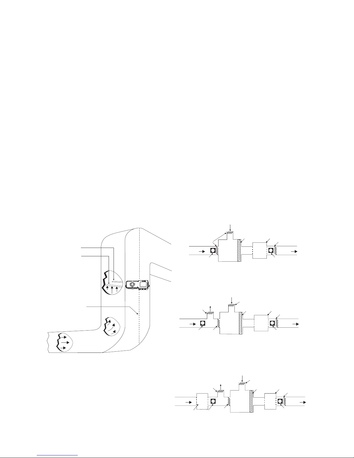
Figure 2
Recommended Locations in Duct Systems
RETURN
AIR
SUPPLY
AIR
AIR DUCT
HOUSING
AIR DUCT
HOUSING
DAMPER
BLOWER
FILTER
PLENUM
FRESH AIR INTAKE
DAMPER
TYPE A: CLOSED SYSTEM - NO EXHAUST
D D
TYPE B: PROVISION FOR EXHAUSTING
SOME PERCENTAGE OF RETURN AIR
RETURN
AIR
SUPPLY
AIR
AIR DUCT
HOUSING
AIR DUCT
HOUSING
DAMPER
DAMPER
BLOWER
FILTER
PLENUM
FRESH AIR INTAKE
DAMPER
D D
EXHAUST AIR
OUTPUT
DAMPER
TYPE C: RETURN AIR UNDER POSITIVE PRESSURE
FROM SEPARATE BLOWER
EXHAUST AIR
OUTPUT
DAMPER
RETURN
AIR
SUPPLY
AIR
AIR DUCT
HOUSING
RETURN AIR
BLOWER
AIR DUCT
HOUSING
DAMPER
DAMPER
BLOWER
FILTER
PLENUM
FRESH AIR INTAKE
DAMPER
D D
Figure 1
Typical Mounting of Duct Housing
OUTLET
TUBE
INPUT
SAMPLING
TUBE
CENTER
LINE
OF DUCT
C
L
Page 5

Siemens Industry, Inc.
Building Technologies Division
5 P/N A6V10330327_a_en
6) Where possible, install duct detectors upstream of air
humidifiers and downstream of dehumidifiers.
7) To prevent false alarms, the duct detector should not be
mounted in areas of extreme high or low temperatures, in
areas where high humidity exists, or in areas where the
duct may contain gases or excessive dust.
Duct Preparation The FDBZ492-PR Housings come with an installation kit that
contains the following items:
• Short return (outlet) tube
• Input sampling tube stopper
• Two #12 x
3
/4” sheet metal screws
• Mounting template (packaged separately)
Remove mounting template. Remove paper backing from the
mounting template and affix it to the duct at the desired
location. Using the template as a guide, drill (2) mounting holes,
3/32" (2.5mm) for the #12 X
3
/4” sheet metal screws packaged in
the installation kit. Drill or punch (2) 1¼” (32mm) holes for input
sampling and outlet tubes, using the template as a guide. Clean
all holes.
Sampling Tube Installation
The FDBZ492-PR duct smoke detectors use a specially notched
sampling tube, which may be ordered separately in one of four
standard lengths.
ST-10 For duct widths of 6" to 1.0’
ST-25 For duct widths of 1.0’ to 3.0’
ST-50 For duct widths of 3.0’ to 5.0 (requires support)
ST-100* For duct widths of 5.0’ to 10.0’ (requires support)
*
This model is supplied as two 5 ft. sections with a coupling.
Assembly is required for installation.
EacEac
EacEac
Eac
h model is manufacth model is manufact
h model is manufacth model is manufact
h model is manufact
ured with a difured with a dif
ured with a difured with a dif
ured with a dif
ferent numberferent number
ferent numberferent number
ferent number
and and
and and
and
sizsiz
sizsiz
siz
e of sampling holes.e of sampling holes.
e of sampling holes.e of sampling holes.
e of sampling holes.
Only the specific t Only the specific t
Only the specific t Only the specific t
Only the specific t
ube must be usedube must be used
ube must be usedube must be used
ube must be used
for the specified duct width.for the specified duct width.
for the specified duct width.for the specified duct width.
for the specified duct width.
Standard sampling tubes are steel tubes with air intake holes
drilled the entire length of the tube. These tubes can be cut to
length and must span at least 80% the width of the duct.
Sampling tubes over 3.0’ must be supported on the opposite
side of the duct. To ensure the correct operation, the red stopper
(stopper in installation kit) must be inserted in the end of the air
input sampling tube. If the input tube protrudes through the
opposite side of the duct, the opening around the tube must be
Page 6

P/N A6V10330327_a_en
Siemens Industry, Inc.
Building Technologies Division
6
sealed. For custom duct widths, always use the next longest
standard size and cut down to the exact requirement.
Once the airflow direction has been determined (refer to Figure
3), insert the input and outlet tubes into the duct housing.
1. Remove the cover from the housing.
2. Loosen the screw and rotate the tube retainer until the
input tube is inserted and oriented properly. Ensure that the
notched end of the tube is inside the housing and that the
air input sampling tube is positioned so that the input holes
are directly facing the airflow.
3. Once the tube is installed, rotate the retainer back into
place and tighten screw.
4. Install the outlet tube in the remaining position. Once the
tube is installed, rotate the retainer back into place and
tighten screw.
Mounting After securing the input and outlet tubes to the duct smoke unit,
(or initially placing the tubes through the 1¼” holes drilled or
punched in the HVAC duct to accept the input and outlet tubes
and then attaching them to the duct unit), hold the duct unit
assembly in position and use (2) # 12 X
3
/4” sheet metal screws
(packaged in the installation kit) to secure the duct smoke
detector to the HVAC duct sheet metal.
INPUT
TUBE HOLES
FACE AIR FLOW
INSERT RED STOPPER
THIS END OF INPUT
TUBE
OUTLET
TUBE INSTALLED
DOWNSTREAM OF AIRFLOW
DO NOT INSERT RED STOPPER
AIR FLOW DIRECTION
DUCT WIDTH
TUBE SUPPORT ONLY FOR DUCTS GREATER THAN 3 FEET WIDE
NOTE: Mountings shown
are typical. Detectors can
be installed side, bottom
or top of duct as long as
proper tube operation and
flow/pressure performance
is maintained.
Figure 3
Sampling Tube Orientation
Page 7

Siemens Industry, Inc.
Building Technologies Division
7 P/N A6V10330327_a_en
Air Duct Sampling Tube Pressure Measurement
The Model PDM-3 Pressure Differential Measuring device
should be used to ensure that the sampling tube pressure
differential is within the specified limits. The differential pressure
between the two tubes should be greater than 0.01 inches of
water and less than 1.2 inches of water. Qualified personnel
should take measurements in accordance with the PDM-3
instructions, P/N 315-085535.
WIRING Conduit Knockouts
To remove plastic knockout, first cut the plastic tab on the
specific knockout. Refer to Figure 4 to locate the tab. Then,
using a screw driver placed at the tab location, tap with a
hammer until the knockout breaks out. Clean the hole before
installing conduit.
3/4” KNOCKOUTS
1/2” KNOCKOUT
PLASTIC
TAB
Figure 4
Removing the Knockouts
Wiring FDBZ492-PR terminal wiring connections are shown in Figure 5.
Note any limitations on the number of detectors and restrictions on
the use of remote devices permitted for each circuit.
Do not use looped wire underDo not use looped wire under
Do not use looped wire underDo not use looped wire under
Do not use looped wire under
t t
t t
t
erminals.erminals.
erminals.erminals.
erminals.
Break wire run to Break wire run to
Break wire run to Break wire run to
Break wire run to
propro
propro
pro
vide forvide for
vide forvide for
vide for
proper proper
proper proper
proper
supervision of connect supervision of connect
supervision of connect supervision of connect
supervision of connect
ions.ions.
ions.ions.
ions.
With detector head removed, connect one of the appropriate
dedicated power sources to the applicable terminals (Refer to
Figure 5). Replace detector head and depress the cover removal
switch (SW1) on the PCB assembly and the unit will be energized. The green power LED will be illuminated, and when
pressing the test/reset button (SW2) on the PCB assembly, the
red alarm LED will be illuminated. This test confirms the correct
basic operation of the duct smoke unit, excluding the detector
head (see functional testing).
Wire the FDBZ492-PR as a stand alone unit as shown in Figure 6.
Wire the FDBZ492-PR as part of a FACP as shown in Figure 7.
Wire the FDBZ492-PR accessories as shown in Figures 7 and 8.
Page 8

P/N A6V10330327_a_en
Siemens Industry, Inc.
Building Technologies Division
8
FAN SUPPLY SOURCE
NC*
NO*
COM*
ALARM RELAY
*See Figure 5 for
terminal block
connections
Figure 5
Wiring the FDBZ492-PR
TB7
TB8
25
24
23
21 22
TB10
TB9
987321654
19
20
18
17
16
15
14
13
12
1110
Figure 6
Stand Alone Wiring the FDBZ492-PR
GNIRIWRP-294ZBDF
LANIMRET
NEERCSKLIS
GNIKRAM
NOITCNUFNOITCENNOC
9BT
1
1YALERMRALA
CNdetcetedekomsnehwdenepO-tcatnocCN-yaler1mralA
2MOCtcatnocMOC-yaler1mralA
3ONdetcetedekomsne
hwdesolC-tcatnocON-yaler1mralA
4
2YALERMRALA
CNdetcetedekomsnehwdenepO-tcatnocCN-yaler2mralA
5MOCtcatnocMOC-
yaler2mralA
6ONdetcetedekomsnehwdesolC-tcatnocON-yaler2mralA
7
ELBUORT
CNedomybdnatslamronnidesolC-tcatnocCN
-yalerelbuorT
8MOCtcatnocMOC-yalerelbuorT
9ONedomybdnatslamronninepO-tcatnocON-yalerelbuorT
01BT
01
/TCENNOCRE
TNI
ETOMER
SEIROSSECCA
TNC-LTRtsetotCDV42ylppA-mralatseT
11+BT elbuortstcetedtinunehwCDV42+-setomerroftuptuo
elbuorttnerrucwoL
21-LTR/-CdnuorG
31+LTR/+CtuptuoCDV42
411LAdetcetedekomsnehwCDV42+-tuptuomralatnerruchgiH
51+LA
detcetedekomsnehwCDV42+-setomerroftuptuomralatnerrucwoL
61+PdevomerrevocrodaehnehwtuC-setomerottuorewoP
7
1+R/TteserrotsetotCDV42ylppA-tupniteseR/tseT
81+CtuptuoCDV42
91
PCAF
MOCtcatnocMOC-yaleRlenaPlortnoCmralAeriF
0
2ON edomybdnatslamronninepO-tcatnocON-yaleRlenaPlortnoCmralAeriF
8BT
12
REWOPTUPNI
CD/CA42evitisopCDV42rotoH
CAV42-tupnirewoP
22O/NevitagenCDV42rolartueNCAV42-tupnirewoP
7BT
32N lartueNCA-tupnirewoP
42511toHCAV511-tupnire
woP
52032toHCAV032-tupnirewoP
Page 9

Siemens Industry, Inc.
Building Technologies Division
9 P/N A6V10330327_a_en
Figure 7
Wiring the FDBZ492-PR to a Fire Alarm Control Panel
Figure 8
FDBZ492-PR Remote Accessory Wiring
FDBZ492-PR
UL Listed
Conventional
Fire Alarm
Control Panel
FDBZ492-PR
N.C. TROUBLE
CONTACT
N.C. TROUBLE
CONTACT
N.O. ALARM
CONTACT
N.O. ALARM
CONTACT
SAMPLE CONTROL PANEL WIRING - STYLE D / CLASS A IDC )*
(Supervised - A fault condition will not inhibit an alarm response
*See Figure 5 for terminal block connections
FDBZ492-PR
UL Listed
Conventional
Fire Alarm
Control Panel
FDBZ492-PR
N.C. TROUBLE
CONTACT
N.C. TROUBLE
CONTACT
N.O. ALARM
CONTACT
N.O. ALARM
CONTACT
SAMPLE CONTROL PANEL WIRING - STYLE B / CLASS B IDC
(Supervised - A fault condition will not inhibit an alarm response)*
*See Figure 5 for terminal block connections
EOL
End
of
Line
for
Specific
FACP
FDBZ492-PR*
FDBZ492-RTL
C-/RTL-
GREEN/
RED
LED
RTL-CNT
C+/RTL+
KEY
SWITCH
(NORMAL/TEST)
5
6
1b
*
See Figure 5 for
terminal block
connections
AL1
AL1
FACP
NO
FACP
NO
C
-
C-
C+
C+
FACP
COM
FACP
COM
+
-
+
-
FDBZ492-PR
#1
FDBZ492-PR
#X
All alarm relays operate with single alarm.
Individual horn/strobe units operate on
alarmed detector only. 30 detectors max.
FDBZ492-PR#1FDBZ492-PR
#X
T/R+
T/R+
C+
C+
Common test/reset. 30 detectors max.
(Use normally open test/reset switch.)
TEST/RESET
SWITCH
FDBZ492-PR
#1
FDBZ492-PR
#X
AL1
AL1
C
+
C
+
All alarm relays operate with
single alarm. 30 detectors max.
A common power supply must be used for all
interconnected detectors.
INTERCONNECTION WIRING FOR COMMON FUNCTIONS*
*See Figure 5 for terminal block connections
AL1
AL1
C
-
C
-
C
+
C
+
+
-
+
-
FDBZ492-PR
#1
FDBZ492-PR
#X
All alarm relays operate with single
alarm. All horn/strobe units operate
as well. 10 detectors max.
Page 10

P/N A6V10330327_a_en
Siemens Industry, Inc.
Building Technologies Division
10
In the event of a fire alarm, certain equipment may be required
to be shut down. For example, shut down may be achieved by
interrupting the fan supply source to that particular piece of
equipment when wired as indicated in Figure 6.
Installation Of Smoke Detectors
To Install:
• Remove cover by loosening the four screws. Take off the
cover and set it aside.
• Align detector with base and insert detector.
• Rotate detector
clockwise while gently pressing on it until
the detector drops fully into base.
• Then rotate the detector clockwise until it stops and snaps
in place.
• Replace cover and tighten the four screws.
To Remove:
• Rotate the detector counterclockwise until stop is reached.
• Pull detector out of base.
TESTING Only qualified service personnel should test these units. To
assure proper operation of the detector and control panel, both
the Sensitivity and the Functional tests should be conducted.
The minimum test schedule may be found in the current edition
of NFPA 72 for installations in the U.S
Sensitivity Test The detectors monitor their smoke sensitivity automatically and
require no test equipment. A green flash of the detector LED or
in the FDBZ492-RTL Remote Accessory indicates that the
smoke sensitivity is within its listed limits.
Functional Test Smoke Testing
Using TG-11 smoke test canister with testing nozzle model
AD-TGN (purchased separately) available from Siemens Industry,
Inc., insert the test gas nozzle into the hole in the red plug in the
unit cover. Press can against cover for about
1
/2 second to
release gas into the chamber.
Do not spraDo not spra
Do not spraDo not spra
Do not spra
y gy g
y gy g
y g
as foras for
as foras for
as for
more than ½ second. more than ½ second.
more than ½ second. more than ½ second.
more than ½ second.
Overuse of t Overuse of t
Overuse of t Overuse of t
Overuse of t
estest
estest
est
gg
gg
g
as maas ma
as maas ma
as ma
y result in dety result in det
y result in dety result in det
y result in det
ectorector
ectorector
ector
cont cont
cont cont
cont
aminataminat
aminataminat
aminat
ion.ion.
ion.ion.
ion.
After 15 to 20 seconds the detector will go into alarm, illuminating the detector LED and causing the duct unit functions to
operate; alarm relays will change state, and the alarm related
remote accessories, if attached, will function.
Page 11

Siemens Industry, Inc.
Building Technologies Division
11 P/N A6V10330327_a_en
If no test gas is available to conduct functional testing, remove
cover and, while holding down the cover removal switch, blow
smoke from a smoldering cotton wick or punk directly at the
head to cause an alarm. The alarm indicator on the detector
should illuminate within one minute.
Refer to the PE-11 Installation Instructions, P/N 315-094198, the
PE-11C Installation Instructions, P/N 315-095626, the 8854
Installation Instructions, P/N 315-094198FA, or the OP121
Installation Instructions, P/N A6V10281367, as applicable, for
additional information on testing these detectors.
MAINTENANCE This unit is equipped with cover removal switch (SW1) that
instantly provides a trouble condition upon removal of the clear
cover. For all testing and inspection with the cover removed, the
cover removal switch (designated as SW1 on PCB) must be
manually depressed to simulate normal operation.
The performance of the air duct detector unit may be adversely
affected by dirt or foreign matter on the sampling tubes or
detector. If the air holes in the input sampling tube become
restricted, the unit cannot receive a proper air sample, and
performance is impaired. It is recommended that the sampling
tubes be checked and cleaned periodically. The detector maintenance program should consist of periodic cleaning of dust from
the detector head by using a vacuum cleaner. For cleaning, refer
to the PE-11 Installation Instructions, P/N 315-094198, the PE-11C
Installation Instructions, P/N 315-095626, or the 8854 Installation
Instructions, P/N 315-094198FA.
UnderUnder
UnderUnder
Under
no circumst no circumst
no circumst no circumst
no circumst
ances is the OP1ances is the OP1
ances is the OP1ances is the OP1
ances is the OP1
21 det21 det
21 det21 det
21 det
ectorector
ectorector
ector
head to be head to be
head to be head to be
head to be
disassembled.disassembled.
disassembled.disassembled.
disassembled.
No repairs or No repairs or
No repairs or No repairs or
No repairs or
cleaning should be at cleaning should be at
cleaning should be at cleaning should be at
cleaning should be at
tt
tt
t
emptempt
emptempt
empt
ed.ed.
ed.ed.
ed.
The cleaning and test program is recommended for 6 month
intervals, or more frequently, if needed, depending on the
individual detector environment. Consult your local code and
AHJ requirements for required maintenance schedules.
UnderUnder
UnderUnder
Under
no circumst no circumst
no circumst no circumst
no circumst
ances is the detances is the det
ances is the detances is the det
ances is the det
ectorector
ectorector
ector
por por
por por
por
tt
tt
t
ion of the PE-1ion of the PE-1
ion of the PE-1ion of the PE-1
ion of the PE-1
11
11
1
,,
,,
,
PE-1PE-1
PE-1PE-1
PE-1
1C or1C or
1C or1C or
1C or
8853 to be disassembled by an 8853 to be disassembled by an
8853 to be disassembled by an 8853 to be disassembled by an
8853 to be disassembled by an
yy
yy
y
one otherone other
one otherone other
one other
than an than an
than an than an
than an
authorizauthoriz
authorizauthoriz
authoriz
ed Siemens Industryed Siemens Industry
ed Siemens Industryed Siemens Industry
ed Siemens Industry
,,
,,
,
Inc. Inc.
Inc. Inc.
Inc.
S S
S S
S
y
y
yy
y
stst
stst
st
ems ems
ems ems
ems
TT
TT
T
ecec
ecec
ec
hnician.hnician.
hnician.hnician.
hnician.
F F
F F
F
oror
oror
or
service,service,
service,service,
service,
cont cont
cont cont
cont
act yact y
act yact y
act y
ourour
ourour
our
nearest authoriz nearest authoriz
nearest authoriz nearest authoriz
nearest authoriz
ed Siemens Industryed Siemens Industry
ed Siemens Industryed Siemens Industry
ed Siemens Industry
,,
,,
,
Inc.Inc.
Inc.Inc.
Inc.
S S
S S
S
ervice Rervice R
ervice Rervice R
ervice R
epresentepresent
epresentepresent
epresent
atat
atat
at
ii
ii
i
ve.ve.
ve.ve.
ve.
If the fire alarm syIf the fire alarm sy
If the fire alarm syIf the fire alarm sy
If the fire alarm sy
stst
stst
st
em is connectem is connect
em is connectem is connect
em is connect
ed to a central sted to a central st
ed to a central sted to a central st
ed to a central st
atat
atat
at
ion orion or
ion orion or
ion or
fire fire
fire fire
fire
depardepar
depardepar
depar
tment,tment,
tment,tment,
tment,
or or
or or
or
operat operat
operat operat
operat
es extes ext
es extes ext
es ext
ernal devices sucernal devices suc
ernal devices sucernal devices suc
ernal devices suc
h as fans,h as fans,
h as fans,h as fans,
h as fans,
ext ext
ext ext
ext
in-in-
in-in-
in-
guishers,guishers,
guishers,guishers,
guishers,
etc., etc.,
etc., etc.,
etc.,
connect connect
connect connect
connect
ed,ed,
ed,ed,
ed,
not
not
not not
not
ify appropriatify appropriat
ify appropriatify appropriat
ify appropriat
e personnel ande personnel and
e personnel ande personnel and
e personnel and
disconnect the extdisconnect the ext
disconnect the extdisconnect the ext
disconnect the ext
ernal devices unternal devices unt
ernal devices unternal devices unt
ernal devices unt
il all til all t
il all til all t
il all t
ests are completests are complet
ests are completests are complet
ests are complet
ed.ed.
ed.ed.
ed.
AfAf
AfAf
Af
tt
tt
t
erer
erer
er
t t
t t
t
estest
estest
est
ing,ing,
ing,ing,
ing,
reset the sy reset the sy
reset the sy reset the sy
reset the sy
stst
stst
st
em,em,
em,em,
em,
reconnect the devices, reconnect the devices,
reconnect the devices, reconnect the devices,
reconnect the devices,
and not and not
and not and not
and not
ifyify
ifyify
ify
the personnel that the sythe personnel that the sy
the personnel that the sythe personnel that the sy
the personnel that the sy
stst
stst
st
em is operatem is operat
em is operatem is operat
em is operat
ing aging ag
ing aging ag
ing ag
ain.ain.
ain.ain.
ain.
Page 12

REMOTE ACCESSORIES
The accessories available for use with FDBZ492-PR are:
SEIROSSECCAETOMER
TOLIP
DEL
)neerG(
MRALA
DEL
)deR(
ELBUORT
DEL
)wolleY(
NROH
SGNITARLACIRTCELE
LEDOM/REBMUNTRAPNOITPIRCSED
YBDNATSMRALAELBUORT
-72S-91345S
LTR-294ZBDF/1A
detarepo-yek,toliP,mralAetomeR
hctiwSteseR/tseT
••
Am2.0Am2.0Am0
SAGTSETEKOMS
057946-005saGtseTrotceteD11-GT
717946-005tiKelzzoNsaGtseTNGT-DA
DAEHROTCETEDEKOMS
0
51490-005rotceteDekomScirtceleotohP11-EP
036590-005rotceteDekomScirtceleotohPC11-EP
AF051490-005rotceteDekomScirtceleotohP4588
1A-1F-27345SrotceteDekomScirtceleotohP121PO
GNISUOHTHGITRETAW
1A-62B-345STW-294ZBDF
COMPATIBLE CONTROL EQUIPMENT
ROTCETED121PO/4588/C11-/11-EPGNISURP-294ZBDF
tnempiuqEeludoM
reifitnedIytilibitapmoC
/noitallatsnIeludoM
snoitcurtsnIgniriW
)SLX-redniFeriF(4-CDC 8-001430-513N/P
)3METSYS(53-PC 22-209480-513N/P
)QI-LXM,LXM(6B1-
MZC* 9-553590-513N/P
)QI-LXM,LXM(4-MZC 01-628090-513N/P
MZH )109CF,429CF,229CF,5002CF,5202CF,0502CF,052-S
F,SLX-redniFeriF( 6-058430-513N/P
XE-LXS 8-799590-513N/P
)XE-LXS(X4-EZS 8-810690-513N/P
)XE-LXS(XA8-EZS 8
-220690-513N/P
)C052-SF(MZS* 4-C058430-513N/P
)3METSYS(53-UZ 81-222380-513N/P
)0007-CPM/0006-CPM(5078 8-90
3744-513N/P
ELECTRICAL RATINGS
4588DNAC11-EP,11-EP
egatloVCDV72-61
elppiRkaep-ot-kaepV3
tnerruCyrosivrepuS.xamAu011
emiTpu-tratS.xamsdnoces0
5
tnerruCmralAAm05-33
121PO
egatloVCDV72-61
elppiRkaep-ot-kaepV3
tnerruCyrosivrepuS.xamAu011
emiTpu-tratS.xamsdnoces03
tnerruCmralAAm
05-03
Siemens Industry, Inc.
Building Technologies Division
Florham Park, NJ
P/N A6V10330327_a_enSiemens Canada Limited
Building Technologies Division
2 Kenview Boulevard
Brampton, Ontario L6T 5E4 Canada
RP-294ZBDF
TUPNI
TNERRUC
TNERRUCYBDNATS
)lacipyT(
TNERRUCMRALA
)lacipyT(
TNERRUCELBUORT
)lacipyT(
CDV42Am92Am321A
m02
zH06@CAV42Am08Am372Am56
zH06@CAV511Am62Am75Am53
zH06@CAV032Am03Am83Am02
 Loading...