

Page 1

A6V10334410_h_en_--
Building Technologies
2015
FDA241, FDA221
Aspirating Smoke Detector
Technical Manual
-09-29 Control Products and Systems
Page 2

Legal notice
2
Legal notice
Technical specifications and availability subject to change without notice.
© Siemens Switzerland Ltd, 2011
Transmittal, reproduction, dissemination and/or editing of this document as well as
utilization of its contents and communication thereof to others without express
authorization are prohibited. Offenders will be held liable for payment of damages.
All rights created by patent grant or registration of a utility model or design patent
are reserved.
Issued by:
Siemens Switzerland Ltd.
Building Technologies Division
International Headquarters
Gubelstrasse 22
CH-6301 Zug
Tel. +41 41 724-2424
www.siemens.com/buildingtechnologies
Edition: 2015-09-29
Document ID: A6V10334410_h_en_--
Building Tec hnologies A6V10334410_h_en_--
Fire Safety 2015 -09-29
Page 3

3
Table of contents
1 About this document ......................................................................................7
1.1 App l icabl e document s .......................................................................................9
1.2 Downl oad center ...............................................................................................9
1.3 Techn ical ter ms ..............................................................................................10
1.4 Revision history ..............................................................................................11
2 Safety ............................................................................................................13
2.1 Safety instructions ..........................................................................................13
2.2 Safety regu lations for the method of operation ................................................14
2.3 Standards and direct i ves complied with ..........................................................16
2.4 Release Notes ................................................................................................16
3 Structure and function .................................................................................17
3.1 Overview ........................................................................................................17
3.1.1 Details for orderi ng...........................................................................20
3.1.2 Product version ES ..........................................................................21
3.2 Setup..............................................................................................................22
3.2.1 Front indicator ..................................................................................24
3.2.2 Int er nal indicator ..............................................................................28
3.2.3 Interface card ...................................................................................29
3.2.4 External power unit and batteries .....................................................31
3.3 Pipe system ....................................................................................................32
3.3.1 Water trap in the pi pe system ...........................................................33
3.4 Parameter settings..........................................................................................34
3.5 Function .........................................................................................................34
3.5.1 Function during operat ion on detec tor line ........................................34
3.5.1.1 Danger levels ...................................................................................35
3.5.1.2 Interface to service devices ..............................................................35
3.5.1.3 Test m ode........................................................................................36
3.5.1.4 Renov ation mode .............................................................................36
3.5.1.5 Line separ ator ..................................................................................36
3.5.1.6 Line tester FDUL221 ........................................................................36
3.5.2 Standalone oper ation .......................................................................37
3.6 Accessories ....................................................................................................37
3.6.1 Communication transponder FDCC221S..........................................37
3.6.2 Power supply kit A (70 W) FP120-Z1................................................37
3.6.3 Battery FA2003-A1 (12 V, 7 Ah, VdS) ..............................................38
3.6.4 Battery FA2004-A1 (12 V, 12 Ah, VdS).............................................38
3.6.5 Battery FA2005-A1 (12 V, 17 Ah, VdS).............................................38
4 Planning ........................................................................................................39
4.1 Compatibility ...................................................................................................39
4.2 Operating modes ............................................................................................39
4.2.1 Parameter Sets ................................................................................40
Building Tec hnologies A6V10334410_h_en_ --
Fire Safety 2015-09-29
Page 4

4
4.3 Power supply .................................................................................................. 41
4.4 Determining the batteries ................................................................................ 42
4.5 Limit s to planning............................................................................................ 43
4.6 Environmental influences ................................................................................ 44
4.7 Blowing-out unit .............................................................................................. 44
5 Mounting / Installation .................................................................................. 45
5.1 Prep arat or y work ............................................................................................ 45
5.1.1 Opening and clos ing the housing cover
when the power supply is switched off.............................................. 45
5.1.2 Opening and clos ing the housing cover
when the power supply is switched on.............................................. 46
5.1.3 Removing and installing the ho usi n g co v er
when the power supply is switched off.............................................. 48
5.1.4 Removing and installing the housing cover
when the power supply is switched on.............................................. 51
5.1.5 Installation position and space requir ements .................................... 55
5.2 Mounting ........................................................................................................ 58
5.2.1 Ad apting the front indicator to the installation pos i tion ...................... 58
5.2.2 Fastening on a level substructure ..................................................... 59
5.2.3 Connecti ng the pipe s ys tem to the aspir ating smok e detector........... 61
5.2.3.1 Return lin e ....................................................................................... 61
5.2.4 Installi ng communication transponder FDCC2 21S............................ 62
5.3 Installation ...................................................................................................... 64
5.3.1 Connecting the external power unit .................................................. 64
5.3.2 'Smoke 4…20 mA' analog output ..................................................... 66
5.3.3 Configurable 'GPI' input ................................................................... 68
5.3.4 'Purge' relay output for blowing out (with FDA241 only) .................... 68
5.3.5 'Dust' relay output for dust value (with FDA241 only) ........................ 69
5.3.6 'Faul t' relay output for er r or messages.............................................. 69
5.3.7 'Inspect' relay output for early warning (FDA241 only) ...................... 69
5.3.8 'PreAlarm ' relay output for pre-alarm ................................................ 70
5.3.9 'Fire 1' rel ay output for fire al ar m 1 ................................................... 70
5.3.10 'Fire 2' rel ay output for fire al ar m 2 ................................................... 70
5.3.11 Connecti ng to th e detec tor line with the FD CC221S ......................... 71
5.3.12 Connecti on to input/ output module ................................................... 72
6 Configuration ................................................................................................ 77
7 Commissioning............................................................................................. 79
7.1 Oper ation on addressed detec tor line (FDnet/C-NET) ..................................... 79
7.2 Standalone application ................................................................................... 82
7.3 Function al test ing of the syst em ...................................................................... 83
7.3.1 Function al test ing of the syst em with an add r essed detec tor line
(FDnet/C-NET) ................................................................................ 83
7.3.2 Function al test ing of the syst em with the stand alone op tion .............. 84
7.4 Testing the ind i cation of fault s on the front indi cator/ inter nal indic ator.............. 86
Building Tec hnologies A6V10334410_h_en_--
Fire Safety 2015 -09-29
Page 5

5
7.5 Testing the airflow...........................................................................................87
7.6 Testing the response time ...............................................................................88
7.7 Checking and testing the power supply units ...................................................89
7.8 LE D and buzzer test .......................................................................................89
7.9 Normalization .................................................................................................90
8 Maintenance / Repair ....................................................................................93
8.1 Visual inspect ion .............................................................................................93
8.2 Checking the pi pe sy s tem ...............................................................................93
8.3 Status quer ies with servic e devic es .................................................................93
8.3.1 Communi cation with the aspirating smoke detector ..........................94
8.4 Resetting status displays and relay outputs (standalone option) ......................96
8.5 Perfo r mance check .........................................................................................97
8.6 Cleaning .........................................................................................................97
8.7 Carrying out water trap maintenance...............................................................97
8.8 Maintenance and cleaning i ntervals ................................................................99
8.9 Event memory .............................................................................................. 100
8.10 Modification memory ..................................................................................... 100
8.11 Faults ........................................................................................................... 101
8.11.1 Table of fau lts ................................................................................ 102
8.11.2 Fault an alysis ................................................................................. 104
9 Specifications ............................................................................................. 105
9.1 Techn ical d ata for FDA241, F DA 221 ............................................................. 105
9.2 Dimensions................................................................................................... 108
9.3 Environmental compatibility and disposal ...................................................... 108
10 Annex .......................................................................................................... 109
10.1 Fault in dication ............................................................................................. 109
Index ..................................................................................................................... 110
Building Tec hnologies A6V10334410_h_en_ --
Fire Safety 2015-09-29
Page 6

6
Building Tec hnologies A6V10334410_h_en_--
Fire Safety 2015 -09-29
Page 7

About this document
1
Applicable documents
7
Target group
Activity
Qualification
1 About this document
Goal and purpose
This document contains all the information you'll need about the following
aspirating smoke detectors:
FDA241
FDA221
Following the instructions consistently will ensure that the product can be used
safely and without any problems.
Intended use
Aspirating smoke detectors FDA241 and FDA221 may only be used for fire
detection and fire control purposes.
Target groups
The information in this document is intended for the following target groups:
Product Manager Is responsible for information passing
between the manufacturer and regional
company.
Coordinates the flow of information
between the individual groups of people
involved in a project.
Project Manager Coordinates the deployment of all
persons and resources involved in the
project according to schedule.
Provides the information required to run
the project.
Project engineer Sets parameters for product depending
on specific national and/or customer
requirements.
Checks operability and approves the
product for commissioning at the place
of installation.
Is responsible for trouble-shooting.
Installation personnel Assembles and installs the product
components at the place of installation.
Carries out a performance check
following installation.
Commissioning personnel Configure the product at the place of
installation according to customerspecific requirements.
Check the product operability and
release the product for use by the
operator.
Searches for and corrects malfunctions.
Maintenance personnel Carries out all maintenance work.
Checks that the products are in perfect
working order.
Searches for and corrects malfunctions.
Has obtained suitable specialist training
for the function and for the products.
Has attended the training courses for
Product Managers.
Has obtained suitable specialist training
for the function and for the products.
Has attended the training courses for
Project Managers.
Has obtained suitable specialist training
for the function and for the products.
Has attended the training courses for
Product Engineer.
Has received specialist training in the
area of building installation technology
or electrical installations.
Has obtained suitable specialist training
for the function and for the products.
Has attended the training courses for
commissioning personnel.
Has obtained suitable specialist training
for the function and for the products.
Building Tec hnologies A6V10334410_h_en_ --
Fire Safety 2015-09-29
Page 8

1
About this document
Applicable documents
8
Source language and reference document
ID code
Examples
on symbols and for identification between steps
The 'i' symbol identifies supplementary information and tips for an easier way of
The source/original language of this document is German (de).
The reference version of this document is the international version in English.
The international version is not localized.
Document identification
The document ID is structured as follows:
ID_ModificationIndex_Language_COUNTRY
-- = multilingual or international
A6V10215123_a_de_DE
A6V10215123_a_en_-A6V10315123_a_--_--
Date format
The date format in the document corresponds to the recommendation of
international standard ISO 8601 (format YYYY-MM-DD).
Conventions for text marking
Markups
Special markups are shown in this document as follows:
⊳ Requirement for a behavior instruction
1.
2.
– Version, option, or detailed information for a behavior instruction
⇨ Intermediate result of a behavior instruction
⇨ End result of a behavior instruction
Numbered lists and behavior instructions with an operation
Behavior instruction with at least two operation sequences
sequence
[➙ X] Reference to a page number
'Text' Quotation, reproduced identically
<Key> Identification of keys
> In addition to relati
in a sequence, e.g., 'Menu bar' > 'Help' > 'Help topics'
↑ Text Identification of a glossary entry
Supplementary information and tips
working.
Building Tec hnologies A6V10334410_h_en_--
Fire Safety 2015 -09-29
Page 9

About this document
1
Applicable documents
9
1.1 Applicable documents
Document ID
Title
You will also find information about search variants and links to mobile
001508 Guidelines Connection factors, line resistances and
capacitances for fire detection systems collective, AnalogPLUS,
interactive, FDnet
007023 Technical manual Input module, input/output module FDCI222,
FDCIO222, FDCIO224
007227 Technical manual Detector exchanger and tester FDUD292
008250 Technical Manual Line tester FDUL221
008331 List of compatibility (for 'Sinteso™' product line)
009052 FS20 Fire detection system - Commissioning, Maintenance,
Troubleshooting
009078 FS20 Fire detection system - Configuration
009718 Technical Manual Intelligent detector tester FDUD293
A6V10210416 FS720 Fire detection system - Commissioning, Maintenance,
Troubleshooting
A6V10210424 FS720 Fire detection system - Configuration
A6V10229261 List of compatibility (for 'Cerberus™ PRO' product line)
A6V10331032 Data sheet Aspirating Smoke Detectors FDA221, FDA241
A6V10332759 Installation, Operation Manual, Configuration 'ASD
Configuration Tool FXS2051'
A6V10334435 Planning, Installation ASD Pipe system
A6V10340094 User Manual 'ASD Asyst Tool FXS2055'
A6V10344957 Installation Manual for 'FXS2055 ASD Asyst Tool'
A6V10345654 Installiotion, Mounting Aspirating Smoke Detectors FDA241,
FDA221
A6V10348930 Driver Installer and Uninstaller for TUSB3410 based devices
A6V10367668 Open-Source Software (OSS) Licenses ASD
A6V10387338 Open-Source Software (OSS) Licenses ASD
A6V10388922 Open-Source Software (OSS) Licenses TUSB3410
A6V10393194 Technical manual Power supply kit A 70 W FP120-Z1
A6V10448753 Data sheet Remote test system for aspirating smoke detectors
(ASD)
1.2 Download center
You can download various types of documents, such as data sheets, installation
instructions, and license texts via the following Internet address:
http://siemens.com/bt/download
Enter the document ID in the 'Find by keyword' input box.
applications (apps) for various systems on the home page.
Building Tec hnologies A6V10334410_h_en_ --
Fire Safety 2015-09-29
Page 10

1
About this document
Technical terms
10
1.3 Technical terms
Term
Explanation
P
ABS Acrylonitrile-butadiene-styrene (plastic)
ASD Aspirating smoke detector
FDnet/C-NET Addressed detector line
GPI General Purpose Input, connection for an external switch
MC link Maintenance and commissioning link
n.c. normally closed (standard state of connection is closed)
n.o. normally open (standard state of connection is open)
PC Personal computer
PC Polycarbonate (plastic)
PSU
SRC1 Optical detection channel in the FDnet/C-NET
SRC3 Channel for monitoring the airflow in the FDnet/C-NET
ower supply unit
Building Tec hnologies A6V10334410_h_en_--
Fire Safety 2015 -09-29
Page 11

About this document
1
Revision history
11
1.4 Revision history
The first edition of a language version or a country variant may, for example, be
Modification index
Edition date
Brief description
New firmware version 3.10 taken into account
New chapters:
Amended chapters:
The language versions and country variants produced by a local company have
me modification index as the corresponding reference document. They are
The reference document's version applies to all languages into which the reference
document is translated.
version 'd' instead of 'a' if the reference document is already this version.
The table below shows this document's revision history:
h 2015-09-29
'Connection to input/output module'
'About this document' ('Intended use' section added); 'Applicable documents';
'Operation on addressed detector line' ('Selection of settings' > 'Smoke alarm
delay time'); 'Testing the airflow' ('Large deviations in the airflow'); 'Power supply';
'Normalization'; 'Table of faults'; ' 'Dust' relay output for dust value (FDA241 only)';
'Technical data FDA241, FDA221'
g 2015-03-03 Data sheet 'Remote test system for aspirating smoke detectors' added in
'Applicable documents' chapter. 'Technical data FDA241, FDA221' chapter
amended and supplemented. Power supply kit FP120-Z1 added. Battery FA2003A1 added. Detector can also be installed horizontally. Editorial changes
f 2014-06-25 Data sheet updated in 'Applicable documents' chapter.
Editorial changes
New chapter with reference to download center added
e 2013-07-02 Change of function when opening housing cover.
d 2012-11-02 Planning limits adapted. Additional references to license document and
commissioning on the detector line. Information added about commissioning and
maintenance. Change to date format in line with ISO 8601 specifications
(yyyy-mm-dd format).
c 2012-03 Document adapted to the following type designation: communication transponder
FDCC221S. Additional information on blowing-out unit. Technical data and
mounting notes added. Additional notes on test mode and about commissioning
on the detector line.
b 2011-12 Revised version
a 2011-10 First edition
the sa
not however included in the table below.
Building Tec hnologies A6V10334410_h_en_ --
Fire Safety 2015-09-29
Page 12

1
About this document
Revision history
12
The table below shows the published language versions and country variants with
Modification index
en_--
de_--
fr_--
it_--
es_--
the corresponding modification index:
h X X X X X
g X X X X X
f – X – – –
e X X X X X
d X X – – –
c - X – – –
b - X – – –
a X X – – –
X = published
– = no publication with this modification index
Building Tec hnologies A6V10334410_h_en_--
Fire Safety 2015 -09-29
Page 13

Safety
2
Safety instructions
13
risks of injury
Signal word
Danger level
DANGER
will result directly in death or
serious injury
WARNING
may result in death or serious
injury
CAUTION
slight to
moderately serious injury
2 Safety
2.1 Safety instructions
The safety notices must be observed in order to protect people and property.
The safety notices in this document contain the following elements:
Symbol for danger
Signal word
Nature and origin of the danger
Consequences if the danger occurs
Measures or prohibitions for danger avoidance
Symbol for danger
This is the symbol for danger. It warns of
Follow all measures identified by this symbol to avoid injury or death.
Additional danger symbols
These symbols indicate general dangers, the type of danger or possible
consequences, measures and prohibitions, examples of which are shown in the
following table:
General danger
Explosive atmosphere
.
NOTICE
Voltage/electric shock
Battery
Laser light
Heat
Signal word
The signal word classifies the danger as defined in the following table:
DANGER identifies a dangerous situation, which
if you do not avoid this situation.
WARNING identifies a dangerous situation, which
if you do not avoid this situation.
CAUTION identifies a dangerous situation, which could result in
if you do not avoid this situation.
NOTICE
identifies possible damage to property that may result from non-
observance.
Building Tec hnologies A6V10334410_h_en_ --
Fire Safety 2015-09-29
Page 14

2
Safety
Safety regulations for the method of operation
14
How risk of injury is presented
WARNING
Nature and origin of the danger
● Measures / prohibitions for danger avoidance
NOTICE
Nature and origin of the danger
● Measures / prohibitions for danger avoidance
WARNING
Electrical voltage
regulations.
Information about the risk of injury is shown as follows:
Consequences if the danger occurs
How possible damage to property is presented
Information about possible damage to property is shown as follows:
Consequences if the danger occurs
2.2 Safety regulations for the method of operation
National standards, regulations and legislation
Siemens products are developed and produced in compliance with the relevant
European and international safety standards. Should additional national or local
safety standards or legislation concerning the planning, mounting, installation,
operation or disposal of the product apply at the place of operation, then these
must also be taken into account together with the safety regulations in the product
documentation.
Electrical installations
Electric shock
● Work on electrical installations may only be carried out by qualified
electricians or by instructed persons working under the guidance and
supervision of a qualified electrician, in accordance with the electrotechnical
Wherever possible disconnect products from the power supply when carrying
out commissioning, maintenance or repair work on them.
Lock volt-free areas to prevent them being switched back on again by mistake.
Label the connection terminals with external external voltage using a
'DANGER External voltage' sign.
Route mains connections to products separately and fuse them with their own,
clearly marked fuse.
Fit an easily accessible disconnecting device in accordance with IEC 60950-1
outside the installation.
Produce earthing as stated in local safety regulations.
Building Tec hnologies A6V10334410_h_en_--
Fire Safety 2015 -09-29
Page 15

Safety
2
Safety regulations for the method of operation
15
Mounting, installation, commissioning and maintenance
If you require tools such as a ladder, these must be safe and must be intended
for the work in hand.
When starting the fire control panel ensure that unstable conditions cannot
arise.
Ensure that all points listed in the 'Testing the product operability' section below
are observed.
You may only set controls to normal function when the product operability has
been completely tested and the system has been handed over to the customer.
Testing the product operability
Prevent the remote transmission from triggering erroneously.
If testing building installations or activating devices from third-party companies,
you must collaborate with the people appointed.
The activation of fire control installations for test purposes must not cause
injury to anyone or damage to the building installations. The following
instructions must be observed:
– Use the correct potential for activation; this is generally the potential of the
building installation.
– Only check controls up to the interface (relay with blocking option).
– Make sure that only the controls to be tested are activated.
Inform people before testing the alarm devices and allow for possible panic
responses.
Inform people about any noise or mist which may be produced.
Before testing the remote transmission, inform the corresponding alarm and
fault signal receiving stations.
Modifications to the system design and the products
Modifications to the system and to individual products may lead to faults,
malfunctioning and safety risks. Written confirmation must be obtained from
Siemens and the corresponding safety bodies for modifications or additions.
Modules and spare parts
Components and spare parts must comply with the technical specifications
defined by Siemens. Only use products specified or recommended by
Siemens.
Only use fuses with the specified fuse characteristics.
Wrong battery types and improper battery changing lead to a risk of explosion.
Only use the same battery type or an equivalent battery type recommended by
Siemens.
Batteries must be disposed of in an environmentally friendly manner. Observe
national guidelines and regulations.
Disregard of the safety regulations
Before they are delivered, Siemens products are tested to ensure they function
correctly when used properly. Siemens disclaims all liability for damage or injuries
caused by the incorrect application of the instructions or the disregard of danger
warnings contained in the documentation. This applies in particular to the following
damage:
Personal injuries or damage to property caused by improper use and incorrect
application
Personal injuries or damage to property caused by disregarding safety
instructions in the documentation or on the product
Personal injury or damage to property caused by poor maintenance or lack of
maintenance
Building Tec hnologies A6V10334410_h_en_ --
Fire Safety 2015-09-29
Page 16
2
Safety
Standards and directives complied with
16
2.3 Standards and directives complied with
WARNING
Limited or non-existent fire detection
detection installation.
NOTICE
Incorrect planning and/or configuration
Additional expense resulting from necessary new planning and/or configuration.
detection installation.
A list of the standards and directives complied with is available from your Siemens
contact.
2.4 Release Notes
Limitations to the configuration or use of devices in a fire detection installation with
a particular firmware version are possible.
Personal injury and damage to property in the event of a fire.
● Read the 'Release Notes' before you plan and/or configure a fire detection
installation.
● Read the 'Release Notes' before you carry out a firmware update to a fire
Important standards and specifications are not satisfied.
Fire detection installation is not accepted for commissioning.
● Read the 'Release Notes' before you plan and/or configure a fire detection
installation.
● Read the 'Release Notes' before you carry out a firmware update to a fire
Building Tec hnologies A6V10334410_h_en_--
Fire Safety 2015 -09-29
Page 17

Structure and function
3
Overview
17
3 Structure and function
3.1 Overview
Aspirating smoke detectors are used for early detection of smoke-generating fires
in rooms and equipment. They are especially suited to applications in which point
detectors are pushed to their limits, cannot be used or can only be used with
restrictions.
The aspirating smoke detector continually takes air from the monitored room using
a connected pipe system with defined aspirating holes. The air is supplied to the
detection chamber and is analyzed for smoke particles using the detector installed
there. The sensitivity of the detector can be adjusted.
The position and size of the aspirating holes are calculated with the 'FXS2055 ASD
Asyst Tool' software. The calculation ensures that the air passes from the
aspirating hole to the detector in the time specified and with the required calculated
sensitivity.
Examples of application
Cavities such as false ceilings or false floors
Rooms with polluted air, in which the pollution has impaired the performance of
optical point detectors
Clean rooms
Rooms the height of which is greater than that permitted for point detectors
Rooms with electromagnetic fields which influence the function of point
detectors
Large rooms up to 800 m²
Separate monitoring of control cabinets and electronics cabinets
Data centers
Telecommunication centers
Mounting lines
Cable tunnels
Conveyor belts
Building Tec hnologies A6V10334410_h_en_ --
Fire Safety 2015-09-29
Page 18

3
Structure and function
Overview
18
The aspirating smoke detector can be operated on an FDnet/C-NET detector line.
1
7
2
3
4
4
56
8
4
8
8
8
When the aspirating smoke detector is operated on a FDnet/C-NET detector line,
For this purpose, communication transponder FDCC221S is also required:
Aspirating smoke detector on addressed detector line
1
Aspirating smoke detector with
communication transponder FDCC221S
2 External power unit with batte ry 6 Fire control panel FC20xx /FC72x
3 Blowin g-out unit (optional) 7 FDnet/C-NET detector line
4 Pipe system 8 FDnet/C-NET peripheral device
the relay outputs are inactive.
5 Return line (optional)
Building Tec hnologies A6V10334410_h_en_--
Fire Safety 2015 -09-29
Page 19

Structure and function
3
Overview
19
Alternatively, various external devices can be connected to the aspirating smoke
1
7
2
3
4
4
5
6
4
8
9
10
detector in standalone operation [➙ 37]:
Aspirating smoke detector in standalone operation
1 Aspirating s moke det ector 6
2 External power unit with batte ry 7 External control/indicator (optional)
3 Blow ing-out un it (optional)
4 Pipe system
5 Return line (optional)
PC with 'FXS2051 ASD Configuration
Tool' software
8 External button (optional)
9
External acoust ic signa l equipment
(optional)
10
External optical signa l equipment
(optional)
Building Tec hnologies A6V10334410_h_en_ --
Fire Safety 2015-09-29
Page 20

3
Structure and function
Overview
20
Properties
Type
Order no.
Designation
Patented technology
Can be used with Siemens FDnet/C-NET loop (with optional FDCC221S
installed)
Extended optical detection thanks to dual wavelengths (blue and infrared)
Configuration via USB or FDCC221S (option)
'Out-of-the-box' installation and commissioning
Early detection of a wider spectrum of particle sizes in the air
Software 'FXS2055 ASD Asyst Tool' and pipe configuration supported
Programmable alarm thresholds
Unique dust-resistant detection chamber
Intuitive front indicator for airflow and smoke value
Normalization of the smoke value
Normalization of the airflow
Access to service functions
Different event protocols
Offline/online configuration supported
FDA241, monitoring area of up to 800 m²
FDA221, monitoring area of up to 500 m²
4…20 mA output
Cleaning function (with FDA241 only)
Firmware can be updated locally
3.1.1 Details for ordering
FDA241 S54333-F17-A1 Aspirating smoke detector (8H)
FDA221 S54333-F15-A1 Aspirating smoke detector (5S)
Building Tec hnologies A6V10334410_h_en_--
Fire Safety 2015 -09-29
Page 21

Structure and function
3
Overview
21
3.1.2 Product version ES
ES
ES
04
Depending on the product and various approvals, the product labels may differ in
The product version ES provides the technical status of a device in terms of
software and hardware. The product version is provided as a two-digit number.
You will find the details of your device's product version:
On the packaging label
On the product label or the type plate
Product version on the packaging label
Details of the product version can be found directly on the packaging label in the
barcode:
Example of a packaging label with details of the product version
Product version on the product label and the type plate
Details of the product version can be found after the device order number:
Example of a product label with details of the product version
terms of the information type and layout.
Look for your device's order number on the product label.
You will find the product version after the order number.
Building Tec hnologies A6V10334410_h_en_ --
Fire Safety 2015-09-29
Page 22

3
Structure and function
Setup
22
3.2 Setup
Position
Part
Function
Components
Overview
1 Housing cover -
2 Front indicator Operating indicators and fault indicators,
connected to the interface card by a cable
3 Opening Cable entry
4 Back box Wall mounting with screws
5 Interface card Connections to external devices and signal
equipment. Depending on the version of the
aspirating smoke detector, not all connections are
available. If the aspirating smoke detector is
operated on a FDnet/C-NET detector line, certain
outputs are not active. See the chapter 'Function
[➙ 34]'.
6 Air inlet Pipe system connection
7 Detection chamber Smoke sensor with flow monitoring
8 Internal indicator Alarm indicator, activate normalization
9 Aspiration unit Fan for aspirating the air.
10 Type plate Relevant identification and detector data
Building Tec hnologies A6V10334410_h_en_--
Fire Safety 2015 -09-29
Page 23

Structure and function
3
Setup
23
Position
Part
Function
11 Mini USB connection for
PC
Interface for configuring the aspirating smoke
detector using the 'FXS2051 ASD Configuration
Tool' software
12 Air outlet Air outlet in the room or return line connection
13 Cables Connection to the front indicator
14 Contact pins Connection for communication transponder
FDCC221S
15 Buzzer Signal tone output
Building Tec hnologies A6V10334410_h_en_ --
Fire Safety 2015-09-29
Page 24

3
Structure and function
Setup
24
3.2.1 Front indicator
The front indicator can be rotated 180° in the housing cover if necessary. See
The front indicator on the housing cover provides a quick overview of the aspirating
smoke detector's current status using LED indicators. The buzzer can be switched
off and a function test for LEDs and buzzers activated using a button.
Front indicator FDA241
Front indicator FDA221
'Adapting the front indicator to the installation position [➙ 58]'.
Building Tec hnologies A6V10334410_h_en_--
Fire Safety 2015 -09-29
Page 25

Structure and function
3
Setup
25
Display
Designation
Function
Operating indication The green LED lights up permanently:
When the power supply is con nected
1
Blowin g-out indicator
The yellow LED lights up permanently:
When the blowing-out process is activated
The yellow LED flashes:
Once the blowing-out process has been act ivated until the normal operating status
is achieved (lasts up to 2 minutes)
Indication of faults The yellow LED flashes:
When there is a technical fa ult
Airflow indicator The current airf low is indicated by an LED in the airflow indicator (b ar graph ind icator).
When the housing cover is opened
a) LED yellow
b) LED green
If a yellow LED lights up, the airflow has increased.
As the deviation increases, the light moves upwards.
If the topmost LED flashes, the airf low has exceeded the upper limit an d the a larm de lay
time has expired.
Example: There may be a leak in the pipe system.
One of the green LEDs lights up.
The airflow is normal.
c) LED yellow
If a yellow LED lights up, the airflow is too low.
As the deviation increases, the indicator moves downwards.
If the bottommost LED flashes, the airflow has fallen below the lower limit and the alarm
delay time has expired.
Example: Some of the as pirating holes in the pipe sy stem may be blocked.
Building Tec hnologies A6V10334410_h_en_ --
Fire Safety 2015-09-29
Page 26

3
Structure and function
Setup
26
Alarming indicator
Number of LEDs lighting up and their meaning
The aspirating smoke detector's current alarm status is ind icated by LEDs in the s moke indicator
(bar grap h indicator).
Yellow LED
Green LED
Smoke indicator
Alarm level
1
Alarm level
Inspect
1…5 'Smoke low'
6…9 ' Inspect'
10…12 'Prealarm'
13…14 'Fire 1'
15 'Fire 2'
The green LED lights up if the level of smoke is minimal.
At the same time, the bottommost 1 to 5 yellow LEDs may indicate minor dev iations.
The red LED lights up at the 'I nspect' alarm lev e l.
At the same time, the bottommost 6 to 9 yellow LEDs light up.
Red LED
Red LED
Red LED
Red LED
Alarm level
Prealarm
Alarm level
Fire 1
Ala rm le vel
Fire 2
The red LED lights up at the 'Prealarm' alarm level.
At the same time, the bottommost 10 to 12 yellow LEDs light up.
The red LED lights up at the ' Fire 1' a lar m level.
At the same time, the bottommost 13 to 14 yellow LEDs light up.
The red LED lights up at the ' Fire 2' a lar m leve l.
At the same time, the 15 yellow LEDs light up.
Building Tec hnologies A6V10334410_h_en_--
Fire Safety 2015 -09-29
Page 27

Structure and function
3
Setup
27
Button
Actio n
Consequence
LED status
Meaning
Press the button br ief ly The buzzer sw itches off
Press and hold the button
A signal test/fault analysis is activated.
(approx. 5 s)
When the housing cover is open , the button takes on the function of the reset button and the alarm
outputs are deactivated. See t he chapter 'Int ernal indicato r [➙ 28]'.
Press the button briefly The buzzer sw itche s off.
The relay outputs are deactivated.
The 4…20 mA analog out put re mains on fault.
Dust indicato r 1 Flashing becomes more frequent as the dust d ensity increases.
Off Normal operation
Slow flashing Low dust v alue
Fast flashing Medium dust va lue
Permanently on High dust value
1
FDA241 only
Building Tec hnologies A6V10334410_h_en_ --
Fire Safety 2015-09-29
Page 28

3
Structure and function
Setup
28
3.2.2 Internal indicator
Indication
Designation
Function
Button
Designation
Function
The 'Normalize Flow' and 'Normalize Smoke' buttons can only be actuated using
When the housing cover [➙ 46] is open, the internal indicator is accessible. The
internal indicator performs the following functions:
Status display for airflow, smoke value, and alarm using 3 LEDs
Activate or stop normalization of the airflow using a button
Activate or stop normalization of the smoke value using a button
Reset self-retaining status displays and relay outputs using a button
Internal indicator
Flow ok The green LED flashes when the airflow is normal.
Smoke ok The green LED flashes when the smoke value is low.
Alarm The red LED flashes during an alarm.
Normalize Flow Button for activating or stopping normalization of the
Normalize Smoke Button for activating or stopping normalization of the
airflow.
smoke value.
Reset Button for resetting the self-retaining status displays
and relay outputs. The current detector status is
reset.
a suitable, thin tool, e.g. a pen or a paper clip.
Building Tec hnologies A6V10334410_h_en_--
Fire Safety 2015 -09-29
Page 29

Structure and function
3
Setup
29
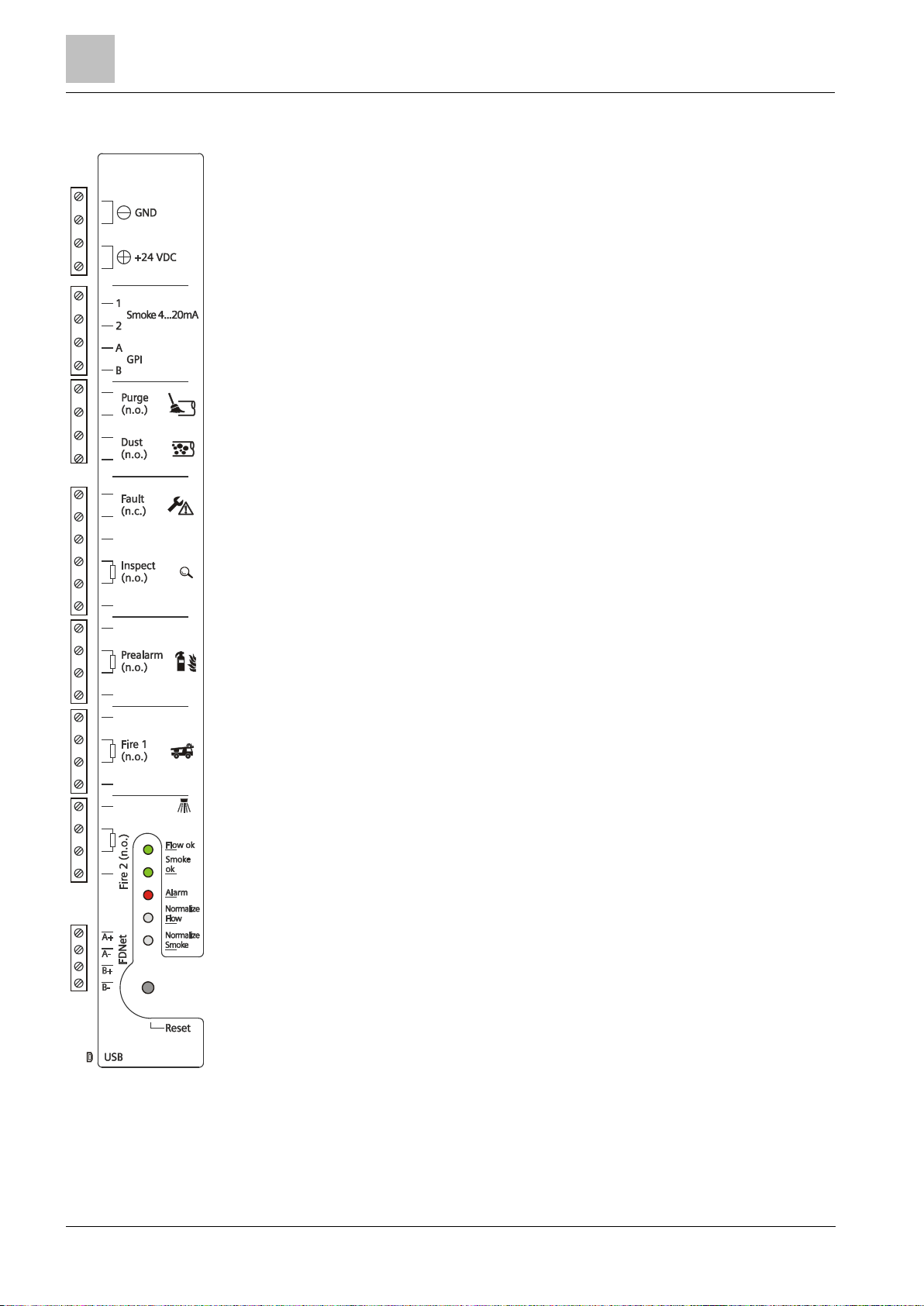
3.2.3 Interface card
The interface card in the back box is accessible once the housing cover has been
removed.
You can do the following on the interface card:
Establish the cable connection to the front display in the housing cover
Connect the external power supply for the aspirating smoke detector
Control various external functions via relays
Install communication transponder FDCC221S (accessory)
Establish a connection to a PC using the mini USB interface
The graphic below provides an overview of the connections together with the
associated symbols and labels.
Building Tec hnologies A6V10334410_h_en_ --
Fire Safety 2015-09-29
Page 30
3
Structure and function
Setup
30
The connection terminals are combined in functional units.
'Smoke 4…20 mA'
'GPI'
'Purge'
'Dust
'Fault'
'Inspect'
'Prealarm'
'Fire 1'
'Fire 2'
'FDNet
'USB'
Power supply
You will find details on page [➙ 64].
analog output. You will find details on p age [➙ 66].
Configurable
You will find details on page [➙ 68].
relay output f or blowing out (with FDA24 1 only)
You will find details on page [➙ 68].
' relay output for dust value (with FDA24 1 only). You w ill find details on page [➙ 69].
relay output for error messages. You will find details on page [➙ 69].
relay output for Ins pect (with FDA241 only)
You will find details on page [➙ 69].
You will find details on page [➙ 70].
relay output for Fire 1
You will find details on page [➙ 70].
relay output for Fire 2
You will find details on page [➙ 70].
' relay connection w ith FDCC 221S (optional)
You will find details on page [➙ 66].
Mini USB port for connecting to a PC
You will find details on page [➙ 94].
input
relay output f or Prealarm
Building Tec hnologies A6V10334410_h_en_--
Fire Safety 2015 -09-29
See also
Communication transponder FDCC221S [➙ 37]
External power unit and batteries [➙ 31]
Removing and installing the housing cover when the power
supply is switched on [➙ 51]
Page 31

Structure and function
3
Setup
31
3.2.4 External power unit and batteries
Company
Type
VdS
For battery type
External power unit
The aspirating smoke detector must be supplied with electricity by an external
power unit. The power unit must satisfy the following requirements:
Version according to EN 54-4
Output voltage: DC 24 V
Output current: 250 mA
The power unit must be connected to the aspirating smoke detector with as
short a cable as possible.
Suitable power unit:
Siemens FP120-Z1 G214130 2x FA2003-A1 (12 V, 7 Ah)
Or
2x FA2004-A1 (12 V, 12 Ah)
Or
You will find more information on the power supply kit FP120-Z1 in
document A6V10393194. See the 'Applicable documents [➙ 9]' chapter.
2x FA2005-A1 (12 V, 17 Ah)
Batteries
If the power supply via the external power unit fails, the power supply of the
aspirating smoke detector must be guaranteed using batteries.
If the aspirating smoke detector is in standalone operation: Observe local
regulations for the minimum detector operation period for power supply failure.
The capacity of the batteries must be selected according to the local
regulations.
If the aspirating smoke detector is being operated on a FDnet/C-NET detector
line: The capacity of the batteries must match the runtime of the connected fire
detection installation if the power supply fails. Observe local regulations for the
fire detection installation.
The batteries are charged using the external power unit. The charging current
for the batteries depends on the battery capacity. You should therefore select
your external power unit to match the batteries' capacity.
See also
Determining the batteries [➙ 42]
Battery FA2003-A1 (12 V, 7 Ah, VdS) [➙ 38]
Battery FA2004-A1 (12 V, 12 Ah, VdS) [➙ 38]
Battery FA2005-A1 (12 V, 17 Ah, VdS) [➙ 38]
Power supply kit A (70 W) FP120-Z1 [➙ 37]
Power supply [➙ 41]
Building Tec hnologies A6V10334410_h_en_ --
Fire Safety 2015-09-29
Page 32

3
Structure and function
Pipe system
32
3.3 Pipe system
3
6
4
3
2
5
2
4
1
The pipe system must be designed according to the calculation with the 'FXS2055
ASD Asyst Tool' software.
The components used for the pipe system must satisfy the requirements according
to document A6V10334435. See 'Applicable documents [➙ 9]'.
Example pipe system for air aspiration
Pipe system
1 Monitored room 4 Aspirating smoke detector
2 Pipes and fittings 5 Outlet line as retu rn line (optional)
3 Hose 6 Outlet line (optional)
Building Tec hnologies A6V10334410_h_en_--
Fire Safety 2015 -09-29
Page 33

Structure and function
3
Pipe system
33
3.3.1 Water trap in the pipe system
The condensation water that has been collected must not enter the airflow and
In the case of highly variable ambient conditions where there is a risk of
condensation water forming in the pipe system, a water trap must be used. The
water trap collects the condensation water. The condensation water must be
drained via a drain hole in the water trap.
must be drained in good time.
Installation site requirements
It must be easy to read the level of water in the water trap.
It must be possible to access the water trap when full for the purpose of
emptying it.
The water trap must be installed at a horizontal point within the pipe system
that is as low as possible. It must not be possible for water to accumulate at
any other point.
Example of how to arrange a water trap
→ → Airf low
1
Aspirating smoke detector with front
indicator that is rotate d by 180°
2
T-fitting for connecting the water trap at a
low horizontal point within the pipe system
3
Distance betwee n manifold and surface of
the water > 300 mm
See also
Adapting the front indicator to the installation position [➙ 58]
Building Tec hnologies A6V10334410_h_en_ --
Fire Safety 2015-09-29
4 Valve for draining cond ensation wate r
5 Outlet open ing
6 Condensat ion water
Page 34

3
Structure and function
Parameter settings
34
3.4 Parameter settings
Relay output
Operation on FDnet/C-NET
detector line
Standalone operation
The information in this chapter only applies to applications in which a
communication transponder FDCC221S (accessory) is installed in the aspirating
smoke detector and the aspirating smoke detector is connected to a compatible
Parameter sets can be used to select the sensitivity with a view to optimizing the
aspirating smoke detector for the current application. You will find information
about selection and application in the chapter 'Operating modes [➙ 39]'.
3.5 Function
The aspirating smoke detector can be used on a FDnet/C-NET detector line or in
standalone operation.
Comparison of the operating types
When operating on a FDnet/C-NET detector line, configuration takes place
using the software for the fire control panel.
– For fire control panels FC20xx: 'SintesoWorks'
– For fire control panels FC72x: 'Cerberus-Engineering-Tool'
In standalone operation: Configuration with the 'FXS2051 ASD Configuration
Tool' software
Controlling the relay outputs on the interface cards
The table below provides an overview of the controlled relay outputs when the
aspirating smoke detector is being operated on an FDnet/C-NET detector line and
in standalone operation:
Purge X X
Dust – X
Fault X X
Infoalarm – X
Prealarm – X
Fire1 – X
Fire2 – X
X = control of relay output
– = no control of relay output
3.5.1 Function during operation on detector line
fire control panel via the FDnet/C-NET.
Building Tec hnologies A6V10334410_h_en_--
Fire Safety 2015 -09-29
Page 35

Structure and function
3
Function
35
3.5.1.1 Danger levels
The evaluation of the danger level and the decisions to be taken (e.g. activation of
The aspirating smoke detector can transmit the following danger levels to the fire
control panel:
Symbol
Danger level _ 1 1 2 3 3
Designation _ Inspect Prealarm Fire 1 Fire 2
Configuration in the
fire detection
installation
Meaning No danger Possible danger Warning Alarm Alarm and extinguishing
Comment Normal Check situation Possible
_ Sensor 1 Sensor 2
Alarm level: Fire 2
Fire The highest danger level 3 has been
danger
reached and the conditions for
activating extinguishing are satisfied.
1
If danger level 1 is frequently transmitted, check whether another sensitivity
setting is more suitable.
remote transmission) are configured in the fire detection system.
3.5.1.2 Interface to service devices
A port with the MC link (maintenance and commissioning link) is installed on
communication transponder FDCC221S.
Using this interface, it is possible to read data from the device with the 'FDUD292
detector exchanger and tester' or the 'FDUD293 intelligent detector tester'.
You will find more information in documents 007227 and 009718.
See also
Applicable documents [➙ 9]
Building Tec hnologies A6V10334410_h_en_ --
Fire Safety 2015-09-29
Page 36

3
Structure and function
Function
36
3.5.1.3 Test mode
For testing purposes the aspirating smoke detectors can be set to test mode. Test
mode does the following:
The relays are deactivated.
The buzzer is operated at a lower sound level.
The green operating indicator flashes.
No changes are made to the sensitivity.
Electronic testing:
The aspirating smoke detectors can be tested on FC20xx/FC72x fire control panels
(market package MP5.0/IP5 or higher) using detector exchanger and tester
FDUD292 or intelligent detector tester FDUD293.
You will find more information in documents 007227 and 009718.
See also
Applicable documents [➙ 9]
3.5.1.4 Renovation mode
When operating the point detectors on the FDnet/C-NET, individual detectors can
be set specifically to renovation mode on the fire control panel.
Select renovation mode if major work is being carried out in the room and large
volumes of dust or aerosols are being produced.
In renovation mode, the detector is operated with the least sensitive parameter set
(no. 10).
See also
Parameter Sets [➙ 40]
3.5.1.5 Line separator
Line separators are electronic switches which isolate the defective part in case of a
short-circuit on the FDnet/C-NET detector line. The rest of the detector line remains
serviceable. On a loop line all FDnet/C-NET devices remain fully functional after a
simple error.
The function of the line separator is integrated in communication transponder
FDCC221S.
See also
Communication transponder FDCC221S [➙ 37]
3.5.1.6 Line tester FDUL221
The line tester FDUL221 detects aspirating smoke detectors on the FDnet/C-NET
detector line.
You will find more information in document 008250.
See also
Applicable documents [➙ 9]
Building Tec hnologies A6V10334410_h_en_--
Fire Safety 2015 -09-29
Page 37

Structure and function
3
Accessories
37
3.5.2 Standalone operation
A fire control panel is not essential to operate the aspirating smoke detector.
Various functions can be directly controlled by the aspirating smoke detector. In the
case of standalone operation, communication transponder FDCC221S must not be
installed.
In standalone operation, the aspirating smoke detector is configured using a PC
with the 'FXS2051 ASD Configuration Tool' software.
3.6 Accessories
3.6.1 Communication transponder FDCC221S
For connecting the aspirating smoke detector to
FDnet/C-NET
Integrated 'line separator' function
Additional MC line interface (port)
Tool-free installation on an intended PCB slot
Supplied with:
– 2 spacer bolts
– 4-pin terminal
– ID adhesive label
Compatible with:
– Aspirating smoke detector FDA241
– Aspirating smoke detector FDA221
Order no.: S24218-A201-A2
See also
Installing communication transponder FDCC221S [➙ 62]
3.6.2 Power supply kit A (70 W) FP120-Z1
For converting the mains voltage into system
voltage
For charging connected batteries
For supplying devices according to EN 54-4
Choice of input voltage between AC 115 V or
AC 230 V
Compatible with:
– Battery FA2003-A1
– Battery FA2004-A1
– Battery FA2005-A1
For details, see document A6V10393194
See also
External power unit and batteries [➙ 31]
Order no.: S4400-S122-A1
Building Tec hnologies A6V10334410_h_en_ --
Fire Safety 2015-09-29
Page 38

3
Structure and function
Accessories
38
3.6.3 Battery FA2003-A1 (12 V, 7 Ah, VdS)
For supplying fire control panels and aspirating
smoke detectors with power
Compatible with:
– Fire control panels for the 'Sinteso' and
'Cerberus PRO' product lines
– External power units for the aspirating smoke
detectors FDA241 and FDA221
VdS approval: G103032
Order no.: A5Q00019353
See also
Determining the batteries [➙ 42]
3.6.4 Battery FA2004-A1 (12 V, 12 Ah, VdS)
For supplying fire control panels and aspirating
smoke detectors with power
Compatible with:
– Fire control panels for the 'Sinteso' and
'Cerberus PRO' product lines
– External power units for the aspirating smoke
detectors FDA241 and FDA221
VdS approval: G103034
Order no.: A5Q00019354
See also
Determining the batteries [➙ 42]
3.6.5 Battery FA2005-A1 (12 V, 17 Ah, VdS)
For supplying fire control panels and aspirating
smoke detectors with power
Compatible with:
– Fire control panels for the 'Sinteso' and
'Cerberus PRO' product lines
– External power units for the aspirating smoke
detectors FDA241 and FDA221
VdS approval: G103035
Order no.: A5Q00019677
See also
Determining the batteries [➙ 42]
Building Tec hnologies A6V10334410_h_en_--
Fire Safety 2015 -09-29
Page 39

Planning
4
Compatibility
39
Detector line
Fire control panel
FC20xx
FC72x
SIGMASYS
AlgoRex
FDnet
C-NET
4 Planning
4.1 Compatibility
Compatible with fire control panels that support the FDnet/C-NET detector line.
You will find detailed information in the 'List of compatibility'.
The table below shows the compatibility of the aspirating smoke detectors and
installed communication transponder FDCC221S with various fire control panels:
X – – –
– X – –
X = compatible
– = not compatible
Please also observe the documentation for your fire detection system.
See also
Applicable documents [➙ 9]
4.2 Operating modes
Three different modes can be set.
'Automatic: switches between blue and blue-red based on ratio'
This mode is suitable for standard use. The sensitivity to small smoke particles is
high and dust suppression is normal. The particle size is taken into account. This
reduces the likelihood of a false alarm.
'Robust'
This mode is suitable for use in dirty rooms where there is a high dust load. The
sensitivity to small smoke particles is lower, but this results in a higher level of dust
suppression. This makes use possible in a dirty environment or in changing
ambient conditions.
'Ultra sense: always blue'
This mode is suitable for use in clean rooms where there is a low dust load. The
sensitivity to small smoke particles is very high and dust suppression is low. As a
result, the detector is very sensitive even to minor changes relating to smoke or
dust in the intake air.
Parameter sets can be used to make further settings with a view to fine-tuning the
product for the installed pipe system. When making your selection, take the
following into account:
Ambient conditions
Place of installation
Usage conditions
Alarm delay
In the FDnet/C-NET, the operating mode and parameter sets can be configured
from the fire control panel.
To determine suitable parameters, use the recommendations from the
'FXS2055 A6V10340094' software.
Building Tec hnologies A6V10334410_h_en_ --
Fire Safety 2015-09-29
Page 40

4
Planning
Operating modes
40
4.2.1 Parameter Sets
Set
No.
Sensitivity [%/m]
Comment
Inspect
Prealarm
Fire 1
Fire 2
Set no.
Sensitivity [%/m]
Comment
Prealarm
Fire 1
Fire 2
The following information applies to the 'Automatic: switches between blue and
blue-red based on ratio' mode.
FDA241
0 0.07 0.10 0.15 20 default
1 0.03 0.04 0.05 2 -
2 0.03 0.045 0.06 2.5 -
3 0.04 0.055 0.07 3 -
4 0.05 0.075 0.10 4 -
5 0.07 0.10 0.15 5 -
6 0.08 0.14 0.20 6 -
7 0.18 0.28 0.40 8 -
8 0.30 0.50 0.70 10 -
9 0.40 0.70 1.00 15 -
10 0.80 1.40 2.00 20 -
FDA221
0 0.50 0.70 20 default
6 0.14 0.20 6 -
7 0.28 0.40 8 -
8 0.50 0.70 10 -
9 0.70 1.00 15 -
10 1.40 2.00 20 -
Building Tec hnologies A6V10334410_h_en_--
Fire Safety 2015 -09-29
Page 41

Planning
4
Power supply
41
4.3 Power supply
The normal status and the alarm status must be taken into account when
dimensioning the power supply. When the normal status applies, the power supply
must provide the quiescent current for the smoke aspiration systems and ensure
that the emergency batteries are charged in accordance with VDE 0883, Part 1.
When the alarm status applies, additional power is required. Take this into account
when dimensioning the batteries. The batteries must be designed to support a
bridging time of 24 hours in the normal status and 1 hour in the alarm status.
You will find details of the aspirating smoke detector's current consumption in
chapter 'Technical data for FDA241, FDA221 [➙ 105]'.
Line calculation
The maximum length of the line is calculated on the basis of the permissible
voltage drop on the supply line. The permissible voltage drop is the difference
between the final voltage of the batteries (21.5 V) and the lower operating voltage
limit of the smoke aspiration systems.
L
= Maximum length of line in [m]
max
∆U = Max. voltage drop on supply line
A
= Wire cross-section in [mm²]
I
= Maximum current of all aspirating smoke detectors in alarm status in [A]
alarm
Ƴ = Specific resistance: Cu = 0.0175 Ω mm²/m
To ensure the housing remains properly sealed, select the relevant grommet for
the cable concerned.
M20 cable grommet: Ø 8…12 mm
M25 cable grommet: Ø 9…14 mm
Also observe the notices in the 'Technical data for FDA241, FDA221 [➙ 105]'
chapter.
Capacity calculation
Use the following formula to calculate the nominal capacity of the batteries:
K
= Nominal capacity of emergency battery in [Ah]
nominal
I
= Quiescent current [A]
quiescent
I
= Maximum current of all aspirating smoke detectors in alarm status in [A]
alarm
n
= Number of aspirating smoke detectors
t
= Required bridging time during operation in [h] (typically 24 h)
1
t
= Required bridging time in the case of an alarm in [h] (typically 1 h)
2
1.25 = The factor of 1.25 ceases to apply with bridging times of more than 24 hours.
See also
External power unit and batteries [➙ 31]
Building Tec hnologies A6V10334410_h_en_ --
Fire Safety 2015-09-29
Page 42

4
Planning
Determining the batteries
42
4.4 Determining the batteries
WARNING
Switching batteries in parallel
● If you need more power, you must use batteries with a higher capacity.
If the aspirating smoke detector's power supply via the external power unit fails,
power is supplied via batteries.
Determining the required battery type
The battery capacity depends on the following conditions:
Buffer time required
Battery age
Country-specific specifications, as regulated in local regulations or European
provisions
The required battery capacity can be identified using the following calculations:
C
= Battery capacity
Batter y
f
= Factor for the battery age
t
= Buffer time
Standby
I
= Internal current of the power supply unit
PSU
t
= Alarm time
Alarm
To achieve the system voltage of DC 24 V, two batteries must be connected in
series.
The buffer times specified in the table apply in the case of an operating
temperature within the range -5…45 °C.
The batteries are charged using the external power unit. The charging current
for the batteries depends on the battery capacity. You should therefore select
your external power unit to match the batteries' capacity.
Risk of explosion and fire
● Never connect batteries in parallel!
See also
Battery FA2003-A1 (12 V, 7 Ah, VdS) [➙ 38]
Battery FA2004-A1 (12 V, 12 Ah, VdS) [➙ 38]
Battery FA2005-A1 (12 V, 17 Ah, VdS) [➙ 38]
Building Tec hnologies A6V10334410_h_en_--
Fire Safety 2015 -09-29
Page 43

Planning
4
Limits to planning
43
4.5 Limits to planning
Observe local regulations and specifications for the limits of the detection range of
the aspirating holes. The local regulations and specifications take priority over all
Detector
Sensitivity
[%/m obs]
Monitored
surface
I-topology
Length of pipe
system
Number of
aspirating holes
(Class A)
Detector
Sensitivity
[%/m obs]
Monitored
surface
U-topology
Length of pipe
system
Number of
aspirating holes
Detector
Sensitivity
[%/m obs]
Monitored
surface
Double U-topology
Length of pipe
system
Number of
aspirating holes
Adherence to the planning limits is verified by the 'FXS2055 ASD Asyst Tool'
other information in this document.
The following limits are set for planning the pipe system depending on the
aspirating smoke detector used.
Single pipe
FDA221 0.14…20 ≤500 m2 ≤30 m ≤12
FDA241 0.03…20 ≤800 m2 ≤60 m ≤16
Branched pipes (symmetrical and asymmetrical U-topology)
FDA221 0.14…20 ≤500 m2 ≤2x 25 m ≤24
FDA241 0.03…20 ≤800 m2 ≤2x 60 m ≤34
FDA241 0.03…20 ≤800 m2 ≤4x 30 m ≤34
software.
The maximum number of aspirating holes depends on the sensitivity and
whether it is a question of class A, B, or C. You will find these details in the
'FXS2055 ASD Asyst Tool' software (see also the table above).
In rooms where there is an increased risk (rooms with ventilation systems), the
size of the monitored area drops to 270…540 m² with the FDA241
(170…340 m² with the FDA221).
The maximum monitored area depends on the topology selected and the overall
maximum pipe length.
See also
Technical data for FDA241, FDA221 [➙ 105]
Building Tec hnologies A6V10334410_h_en_ --
Fire Safety 2015-09-29
Page 44

4
Planning
Environmental influences
44
4.6 Environmental influences
Always ensure that the blowing-out unit used for blowing out is suitable.
If the devices are used in industrial applications, consultation with the project
manager is required, since plastics do not withstand certain environmental
conditions.
The following factors must be taken into consideration:
Chemicals
Temperature
Moisture
Fluctuations in air pressure, e.g. in well aerated rooms
4.7 Blowing-out unit
Deposits at the aspirating holes affect air aspiration and have the potential to
trigger an alarm. The pipe system should be blown out to purge it. To do this,
compressed air is introduced into the pipe system. The compressed air clears
deposits from the aspirating holes and capillary tubes. The aspirating smoke
detector features an output for the purpose of controlling a blowing-out unit.
Find out about any local regulations.
Blowing out unit requirements
The blowing-out unit must be approved in accordance with local regulations.
The aspirating smoke detector must not be subject to pressure.
– No compressed air is permitted to enter the aspirating smoke detector
during blowing out.
– The blowing-out unit must feature suitable valves.
– For blowing out purposes, it must be possible to disconnect the pipe
system from the aspirating smoke detector.
Once blowing out has been performed, it must be possible to reconnect the
pipe system to the aspirating smoke detector.
Building Tec hnologies A6V10334410_h_en_--
Fire Safety 2015 -09-29
Page 45

Mounting / Installation
5
Preparatory work
45
NOTICE
Electrostatic discharge
Ground yourself immediately before opening the housing, e.g. by touching a
ground point or wearing an anti-static belt.
1 2
5 Mounting / Installation
5.1 Preparatory work
5.1.1 Opening and closing the housing cover when the power
supply is switched off
When the housing cover is open, the mini USB connection and the internal
indicators are accessible.
Damage to electronic components in the aspirating smoke detector
● When working on the open aspirating smoke detector, use anti-static floor
mats and anti-static work surfaces.
●
Opening the housing cover
Opening the housing cover
The housing is free from dust.
1. Remove the two screws on the top of the aspirating smoke detector using a
size 2 Phillips screwdriver (step 1).
2. Slide the housing cover in the direction of the arrow until it snaps into place
(step 2).
The housing cover is open.
Building Tec hnologies A6V10334410_h_en_ --
Fire Safety 2015-09-29
Page 46

5
Mounting / Installation
Preparatory work
46
Closing the housing cover
NOTICE
Electrostatic discharge
Ground yourself immediately before opening the housing, e.g. by touching a
ground point or wearing an anti-static belt.
NOTICE
Accidental triggering of an alarm
Closing the housing cover automatically reactivates the relay outputs and the
4…20 mA analog output switches to normal operation.
The size 2 Phillips screwdriver and the two screws are available.
The power supply is switched off.
1. Slide the housing cover in the opposite direction to the arrow (step 2) until it
reaches the end position at the bottom.
2. NOTICE! Connection cable clamped between the back box and the housing
cover. Damage to the cable! Be aware of the connection cable when closing
the housing cover.
3. Screw the housing cover to the housing base with the two screws. Tighten the
screws by hand (step 1).
The housing cover is closed.
5.1.2 Opening and closing the housing cover when the power
supply is switched on
When the housing cover is open, the mini USB connection and the internal
indicators are accessible.
Damage to electronic components in the aspirating smoke detector
● When working on the open aspirating smoke detector, use anti-static floor
mats and anti-static work surfaces.
●
Triggering a false alarm
● When the housing cover is opened, the buzzer sounds. The relay outputs
remain active and the 4…20 mA analog output has been switched to fault
(0.5 mA).
● If the button is pressed, the buzzer switches off and the relay
outputs are deactivated. The 4…20 mA analog output remains on fault.
●
Building Tec hnologies A6V10334410_h_en_--
Fire Safety 2015 -09-29
Page 47

Mounting / Installation
5
Preparatory work
47
1 2
Opening the housing cover
Opening the housing cover
The housing is free from dust.
1. Remove the two screws on the top of the aspirating smoke detector using a
size 2 Phillips screwdriver (step 1).
2. Slide the housing cover in the direction of the arrow until it snaps into place
(step 2).
The housing cover is open.
Opening of the housing is logged in the modification memory.
The
The relay outputs remain active and the 4…20 mA analog output has been
switched to fault (0.5 mA).
3. Press the button to switch off the buzzer.
The relay outputs are deactivated.
The 4…20 mA analog output remains on fault.
The housing cover is open.
fault indicator flashes and the buzzer is switched on.
Building Tec hnologies A6V10334410_h_en_ --
Fire Safety 2015-09-29
Closing the housing cover
The size 2 Phillips screwdriver and the two screws are available.
1. Slide the housing cover in the opposite direction to the arrow (step 2) until it
reaches the end position at the bottom.
2. NOTICE! Connection cable clamped between the back box and the housing
cover. Damage to the cable! Be aware of the connection cable when closing
the housing cover.
Closing the housing cover automatically reactivates the relay outputs and
the 4…20 mA analog output switches to normal operation.
Closing of the housing is logged in the modification memory.
The fault indicator
3. Screw the housing cover to the housing base with the two screws. Tighten the
screws by hand (step 1).
The housing cover is closed.
goes out and the audio warning is switched off.
Page 48

5
Mounting / Installation
Preparatory work
48
5.1.3 Removing and installing the housing cover when the power
NOTICE
Electrostatic discharge
Ground yourself immediately before opening the housing, e.g. by touching a
ground point or wearing an anti-static belt.
1 2
3
4
5
A
A
B
B
supply is switched off
Damage to electronic components in the aspirating smoke detector
● When working on the open aspirating smoke detector, use anti-static floor
mats and anti-static work surfaces.
●
When the housing cover is removed, you have access to:
The fixing screws
The cable entry
All the mechanical components
The electrical connections
The rear of the front indicator
Removing the housing cover
Building Tec hnologies A6V10334410_h_en_--
Fire Safety 2015 -09-29
Page 49

Mounting / Installation
5
Preparatory work
49
Removing the housing cover
The removed housing cover can be hung on the back box.
The housing is free from dust.
Do not disconnect the connection cable running between the housing cover
and the back box.
1. Remove the two screws on the top of the aspirating smoke detector using a
size 2 Phillips screwdriver (step 1).
2. Slide the housing cover in the direction of the arrow until it snaps into place
(step 2).
The housing cover is open.
3. Take hold of the housing cover on the left and right (A) and pull the side walls
apart (step 3).
4. Lift the housing cover off the back box (B). When doing this, be aware of the
connection cable (step 3).
The housing cover is removed.
Hanging the removed housing cover on the back box
Building Tec hnologies A6V10334410_h_en_ --
Fire Safety 2015-09-29
Page 50

5
Mounting / Installation
Preparatory work
50
Installing the housing cover
2
2
1
Markings on the housing cover and back box
The size 2 Phillips screwdriver and the two screws are available.
1. Connect the connection cable plug to the interface card!
2. Place the housing cover on the back box so that marking (1) is located
between both of the (2) markings.
3. Push the housing cover onto the back box in the direction of the arrow until the
housing cover snaps into place.
4. NOTICE! Connection cable clamped between the back box and the housing
cover. Damage to the cable! Be aware of the connection cable when closing
the housing cover.
5. Slide the housing cover in the opposite direction to the arrow (step 2) until it
reaches the end position at the bottom.
6. Screw the housing cover to the housing base with the two screws. Tighten the
screws by hand.
The aspirating smoke detector's housing cover is installed.
Building Tec hnologies A6V10334410_h_en_--
Fire Safety 2015 -09-29
Page 51

Mounting / Installation
5
Preparatory work
51
5.1.4 Removing and installing the housing cover when the power
NOTICE
Electrostatic discharge
ground point or wearing an anti-static belt.
NOTICE
Accidental triggering of an alarm
Closing the housing cover automatically reactivates the relay outputs and the
4…20 mA analog output switches to normal operation.
supply is switched on
Damage to electronic components in the aspirating smoke detector
● When working on the open aspirating smoke detector, use anti-static floor
mats and anti-static work surfaces.
● Ground yourself immediately before opening the housing, e.g. by touching a
Triggering a false alarm
● When the housing cover is opened, the buzzer sounds. The relay outputs
remain active and the 4…20 mA analog output has been switched to fault
(0.5 mA).
● If the button is pressed, the buzzer switches off and the relay
outputs are deactivated. The 4…20 mA analog output remains on fault.
●
When the housing cover is removed, you have access to:
The fixing screws
The cable entry
All the mechanical components
The electrical connections
The rear of the front indicator
Building Tec hnologies A6V10334410_h_en_ --
Fire Safety 2015-09-29
Page 52

5
Mounting / Installation
Preparatory work
52
1 2
3
4
5
A
A
B
B
Removing the housing cover
Removing the housing cover
The housing is free from dust.
Do not disconnect the connection cable running between the housing cover
and the back box.
1. Remove the two screws on the top of the aspirating smoke detector using a
size 2 Phillips screwdriver (step 1).
2. Slide the housing cover in the direction of the arrow until it snaps into place
(step 2).
Building Tec hnologies A6V10334410_h_en_--
Fire Safety 2015 -09-29
The housing cover is open.
Opening of the housing is logged in the modification memory.
The
fault indicator flashes and the buzzer is switched on.
The relay outputs remain active and the 4…20 mA analog output has been
switched to fault (0.5 mA).
3. Press the button to switch off the buzzer.
The relay outputs are deactivated.
The 4…20 mA analog output remains on fault.
4. Take hold of the housing cover on the left and right (A) and pull the side walls
apart (step 3).
5. Lift the housing cover off the back box (B). When doing this, be aware of the
connection cable (step 3).
The housing cover is removed.
Page 53

Mounting / Installation
5
Preparatory work
53
The removed housing cover can be hung on the back box.
If the connection cable does need to be disconnected, you must switch off the
Hanging the removed housing cover on the back box
power supply before removing the cable from the interface card.
Building Tec hnologies A6V10334410_h_en_ --
Fire Safety 2015-09-29
Page 54

5
Mounting / Installation
Preparatory work
54
Installing the housing cover
2
2
1
Markings on the housing cover and back box
The size 2 Phillips screwdriver and the two screws are available.
1. Connect the connection cable plug to the interface card!
2. Place the housing cover on the back box so that marking (1) is located
between both of the (2) markings.
3. Push the housing cover onto the back box in the direction of the arrow until the
housing cover snaps into place.
4. NOTICE! Connection cable clamped between the back box and the housing
cover. Damage to the cable! Be aware of the connection cable when closing
the housing cover.
5. Slide the housing cover in the opposite direction to the arrow (step 2) until it
reaches the end position at the bottom.
The fault indicator goes out.
The relay outputs are automatically reactivated.
The 4…20 mA analog output switches to normal operation.
6. Screw the housing cover to the housing base with the two screws. Tighten the
screws by hand.
The aspirating smoke detector's housing cover is installed.
Building Tec hnologies A6V10334410_h_en_--
Fire Safety 2015 -09-29
Page 55

Mounting / Installation
5
Preparatory work
55
5.1.5 Installation position and space requirements
A
D
Installation site requirements
Only to be installed within a building where the ambient conditions are
permissible
No direct sunlight
Take into account the additional space required by and the need to access the
following:
– External power unit and batteries
– Blowing-out unit (optional)
– Water trap (optional)
The aspirating smoke detector can be installed either horizontally or vertically
on a level surface.
The dust load should be low at the installation site, because the aspirating
smoke detector housing is opened for maintenance purposes.
Ensure that there is at least 150 mm of free space on each side of the installed
aspirating smoke detector to ensure the pipe system and electrical connections
can be installed with ease.
Connecting to the pipe system
The aspirating smoke detector can be installed in different installation locations.
The installation location to be used depends on the pipe system's connection to the
aspirating smoke detector.
Aspirating smoke detectors with different installation locations
Building Tec hnologies A6V10334410_h_en_ --
Fire Safety 2015-09-29
Page 56

5
Mounting / Installation
Preparatory work
56
Four connection types are possible:
When the aspirating smoke detector is installed horizontally, no adapted
410 mm
1
7
0
m
m
1
2
0
m
m
A B
C
D E
A
Aspiration from above
B
Aspiration from below
C
Space required by the aspirating smoke detector when the housing cover is
D
Aspiration from left
E
Aspiration from right
Standard: From above (A)
From below (B) when the aspirating smoke detector is installed rotated by 180°
From left (D) or right (E) when the aspirating smoke detector is installed
horizontally
alignment of the front panel is possible. See 'Adapting the front indicator to the
installation position [➙ 58]'.
Installation position
open
Building Tec hnologies A6V10334410_h_en_--
Fire Safety 2015 -09-29
Page 57

Mounting / Installation
5
Preparatory work
57
Cable entry
Position of hole
Size of hole
If the aspirating smoke detector is installed rotated by 180°, the circular
110 mm
25 x 100 mm
25 mm
20 mm
Breakthrough on rear 25 x 100 mm
Breakthrough on left side of housing Diameter 25 mm
Breakthrough on top of housing Diameter 25 mm
breakthroughs are found on the bottom at the right-hand side.
Cable entry with standard installation position
To prepare the electrical connections, perform the following steps:
1. Break through the necessary cable entries (e.g., using a screwdriver).
2. Attach the plastic cable entries (usual size M20) to the housing.
3. Insert the cables through the relevant cable entries.
See also
Adapting the front indicator to the installation position [➙ 58]
Technical data for FDA241, FDA221 [➙ 105]
Building Tec hnologies A6V10334410_h_en_ --
Fire Safety 2015-09-29
Page 58

5
Mounting / Installation
Mounting
58
5.2 Mounting
180°
8x
8x
1
2
4
3
5.2.1 Adapting the front indicator to the installation position
The aspirating smoke detector can be installed rotated by 180° if required. The
front indicator must then also be installed rotated by 180°.
Adapting the front indicator to the installation position
The housing cover has been removed (step 1).
1. Loosen the 8 screws on the inside of the housing cover (step 2).
2. Rotate the front indicator by 180° (step 3).
3. Fasten the front indicator to the housing cover using the 8 screws (step 4).
The front indicator is adapted to the installation position.
Building Tec hnologies A6V10334410_h_en_--
Fire Safety 2015 -09-29
Page 59

Mounting / Installation
5
Mounting
59
5.2.2 Fastening on a level substructure
The mounting holes in the back box are not symmetrical, so use the drilling
1
3
2
4x
A drilling template is punched in the inner packaging of the aspirating smoke
detector packaging.
The punched symbol in the center of the packaging indicates the airflow direction
(air inlet and air outlet).
template.
Using the drilling template
4 screws with a shaft diameter of 5…6 mm and a head diameter of 8…10 mm
are available.
A suitable tool for drilling and screwing is available.
The housing cover is removed and the cable loosened.
The product must be installed on a level, non-combustible base.
1. Use the unfolded packaging as the drilling template.
– Note the arrow symbol for the direction of the pipe connections (step 3).
2. Drill the mounting holes.
3. If necessary: Use suitable dowels.
Building Tec hnologies A6V10334410_h_en_ --
Fire Safety 2015-09-29
Page 60

5
Mounting / Installation
Mounting
60
4. Screw the four screws into the mounting holes.
– Do not screw in the screws as far as the stop. A gap of approx. 10 mm
must remain between the screw head and the wall.
5. Hang the back box on the screws.
6. Carefully tighten the four screws.
The back box is fastened.
7. Reconnect the cable and close the housing cover.
The aspirating smoke detector is installed.
Building Tec hnologies A6V10334410_h_en_--
Fire Safety 2015 -09-29
Page 61

Mounting / Installation
5
Mounting
61
5.2.3 Connecting the pipe system to the aspirating smoke
NOTICE
Connection between pipe system and aspirating smoke detector
maintenance work or repairs, components may be damaged.
NOTICE
Connection between aspirating smoke detector and return line
Do not glue the return line to the aspirating smoke detector! If the return line
has to be separated from the aspirating smoke detector for maintenance work
or repairs, the return line or the aspirating smoke detector may be damaged.
detector.
detector
Damage to the pipe system and/or the aspirating smoke detector
● Do not glue the pipe system to the aspirating smoke detector! If the pipe
system has to be separated from the aspirating smoke detector for
The pipe system is installed.
The last 500 mm of the pipe system on the aspirating smoke detector must be
straight, such that flow turbulences can be eliminated before entering the
aspirating smoke detector.
1. Press a short pipe securely into the air inlet on the aspirating smoke detector.
2. Connect the pipe system and the pressed-in pipe piece to the aspirating smoke
detector.
The pipe system is connected to the aspirating smoke detector.
You will find more information in document A6V10334435.
5.2.3.1 Return line
If there is an air pressure difference of >45 Pa between the monitored area and the
aspirating fire detector, a return line is required.
Damage to the return line and/or the aspirating smoke detector
●
Press the return line securely into the air outlet on the aspirating smoke
You will find more information in document A6V10334435.
See also
Applicable documents [➙ 9]
See also
Applicable documents [➙ 9]
Building Tec hnologies A6V10334410_h_en_ --
Fire Safety 2015-09-29
Page 62

5
Mounting / Installation
Mounting
62
5.2.4 Installing communication transponder FDCC221S
Communication transponder FDCC221S may only be installed if the aspirating
smoke detector is connected to FDnet/C-NET. Installation is not permitted in the
case of standalone operation.
Communication transponder FDCC221S has its own ID. The ID of communication
transponder FDCC221S is made visible to the detector line and it replaces the ID
of the aspirating smoke detector.
Installing communication transponder FDCC221S in an aspirating smoke detector
Changes on the type plate when the FDCC221S is installed
1 Mark indicating that th e FDCC221S is installed
2 ID adhes ive label from FDCC221S for aspirating smoke detector
3 Tear-off adhesive label for installation plan
Building Tec hnologies A6V10334410_h_en_--
Fire Safety 2015 -09-29
Page 63

Mounting / Installation
5
Mounting
63
Mounting
Only start the detector line when the external power supply for the aspirating
The housing cover is open.
The aspirating smoke detector's external power supply is switched off and
disconnected from the aspirating smoke detector.
A communication transponder FDCC221S (accessory) is available.
1. Insert communication transponder FDCC221S into the aspirating smoke
detector's interface card with the two spacer bolts as shown in the diagram.
2. On the type plate of the aspirating smoke detector, place a mark in the
'FDCC221S is installed' field (1).
3. Use the two ID adhesive labels from the FDCC221S as described below:
– Take the first ID adhesive label and stick it over the type plate of the
aspirating smoke detector (2).
– Use the second ID adhesive label for the installation plan.
– Remove the tear-off adhesive label from the aspirating smoke detector and
dispose of it (3).
4. After switching off the detector line, connect it to communication
transponder FDCC221S. You will find the terminal assignment in the
'Connecting to the detector line with the FDCC221S [➙ 71]' chapter.
5. Re-connect the switched off external power supply for the aspirating smoke
detector.
6. Close the housing cover.
Communication transponder FDCC221S is installed and connected to the
detector line.
smoke detector has been established.
See also
Communication transponder FDCC221S [➙ 37]
Building Tec hnologies A6V10334410_h_en_ --
Fire Safety 2015-09-29
Page 64

5
Mounting / Installation
Installation
64
5.3 Installation
CAUTION
Electrical voltage on lines
During mounting and installation work, electrical voltage must not be applied
to the lines.
Note the positive and negative poles.
Only connect one wire per terminal. This is the only way to ensure the connection
Risk of injury due to electric shock
●
is failure-free for the entire service life of the device.
5.3.1 Connecting the external power unit
Two connection terminals are available for the aspirating smoke detector's power
supply. This allows more aspirating smoke detectors to be connected to a power
unit.
Prerequisite: The power unit used satisfies the requirements according to the
'External power unit and batteries' chapter.
Connection diagram for 'one aspirating smoke detector on one power
unit'
Connection without forwarding to other aspirating smoke detectors
Connection diagram for 'multiple aspirating smoke detectors on one
power unit'
Connection with forwarding to other aspirating smoke detectors
IN Connection of external power unit
OUT Connection for the power supply of other aspirating smoke detectors
Properties
Protected against polarity reversal
Connection of more aspirating smoke detectors
Building Tec hnologies A6V10334410_h_en_--
Fire Safety 2015 -09-29
Page 65

Mounting / Installation
5
Installation
65
Procedure
A suitable external power unit is available.
The aspirating smoke detector's housing cover is removed.
1. Before connecting the external power unit to the terminal block, check the
voltage provided by the power unit. Permissible value: DC 24 V ±4 V
2. Connect the power unit to the aspirating smoke detector(s) according to the
connection diagram shown.
The external power unit is connected to the aspirating smoke detector(s).
See also
External power unit and batteries [➙ 31]
Power supply kit A (70 W) FP120-Z1 [➙ 37]
Building Tec hnologies A6V10334410_h_en_ --
Fire Safety 2015-09-29
Page 66

5
Mounting / Installation
Installation
66
5.3.2 'Smoke 4…20 mA' analog output
Smoke value (device default)
4…20 mA analog output
Airflow
4…20 mA analog output
Configurable 4…20 mA analog output.
The setting is made in the 'Current loop' menu with the 'FXS2051 ASD
Configuration Tool' software for one of the following values:
Smoke value (device default)
Dust value (FDA241 only)
Airflow (FDA241 only)
Fine dust value (FDA241 only)
Example illustrating analog input (IN)
Connection for DC 9…25 V power supply
No smoke 4 mA
Inspect 8 mA
Prealarm 12 mA
Fire 1 16 mA
Fire 2 20 mA
0 l/min 4 mA
20 l/min 8 mA
40 l/min 12 mA
60 l/min 16 mA
80 l/min 20 mA
Building Tec hnologies A6V10334410_h_en_--
Fire Safety 2015 -09-29
Page 67

Mounting / Installation
5
Installation
67
Dust value
4…20 mA analog output
Fine dust value
4…20 mA analog output
No dust 4 mA
Low dust value 8 mA
Medium dust value 12 mA
High dust value 16 mA
Very high dust value 20 mA
0 μg/m³ 4 mA
30 μg/m³ 8 mA
60 μg/m³ 12 mA
90 μg/m³ 16 mA
150 μg/m³ 20 mA
Properties
With electrically isolated, passive two-wire 4…20 mA analog output.
The connection is independent of polarity.
The increment corresponds to the increment of the smoke indicator (bar graph
indicator). [➙ 24]
The error indicator can be suppressed with the 'FXS2051 ASD Configuration
Tool' software.
'Current loop' output.
Building Tec hnologies A6V10334410_h_en_ --
Fire Safety 2015-09-29
Page 68

5
Mounting / Installation
Installation
68
5.3.3 Configurable 'GPI' input
Configurable input for an external switch. The setting is made in the 'Relay and
GPI' menu with the 'FXS2051 ASD Configuration Tool' software.
Monitoring for open line
Monitoring for short circuit and open line
Properties
Can be configured to trigger the following actions:
– Switching to Manned/Unmanned (not possible when fire control panel
FC20xx/FC72x is connected)
– Resetting
– Activating blowing-out unit
– Deactivates all relays and alarm outputs
Monitoring for open line (1 resistor)
Monitoring for short circuit and open line (2 resistors)
Input for error monitoring on the external power unit
5.3.4 'Purge' relay output for blowing out (with FDA241 only)
Relay output for controlling an external blowing-out unit.
Connection: n.o.
Properties
Suitable for controlling an external blowing-out unit.
Configuration of:
– Purge interval
– Purge duration
When the aspirating smoke detector is in operation, the setting is made on the
FDnet/C-NET using the fire control panel configuration software.
For fire control panels FC20xx: 'SintesoWorks'
For fire control panels FC72x: 'Cerberus-Engineering-Tool'
When the aspirating smoke detector is in standalone operation, the setting is made
in the 'Purge' menu with the 'FXS2051 ASD Configuration Tool' software.
Building Tec hnologies A6V10334410_h_en_--
Fire Safety 2015 -09-29
Page 69

Mounting / Installation
5
Installation
69
5.3.5 'Dust' relay output for dust value (with FDA241 only)
State
Relay
Relay output for external monitoring of the dust value.
Connection: n.o.
Properties
Suitable for external monitoring of the dust value.
Is activated with increased dust concentration.
5.3.6 'Fault' relay output for error messages
Relay output for error messages.
Normal (no error) Closed
Error or disconnected from the power supply Open
Connection: n.c. (default setting)
Properties
The relay deactivates if an error occurs.
5.3.7 'Inspect' relay output for early warning (with FDA241 only)
Relay output for early warning.
Connection: n.o. (default setting) and resistance according to specification of the
connected device.
Properties
Activation occurs according to the chosen setting.
The connection can be changed to 'n.c.' with the 'FXS2051 ASD Configuration
Tool' software. The chosen setting applies automatically to 'Inspect', 'Prealarm',
'Fire 1', 'Fire 2'.
Building Tec hnologies A6V10334410_h_en_ --
Fire Safety 2015-09-29
Page 70

5
Mounting / Installation
Installation
70
5.3.8 'PreAlarm' relay output for pre-alarm
Relay output for 'pre-alarm' alarm level.
Connection: n.o. (default setting)
Properties
Activation occurs according to the chosen setting.
The connection can be changed to 'n.c.' with the 'FXS2051 ASD Configuration
Tool' software. The chosen setting applies automatically to 'Inspect', 'Prealarm',
'Fire 1', 'Fire 2'.
5.3.9 'Fire 1' relay output for fire alarm 1
Relay output for alerting the fire brigade.
Connection: n.o. (default setting)
Properties
Activation occurs according to the chosen setting.
The connection can be changed to 'n.c.' with the 'FXS2051 ASD Configuration
Tool' software. The chosen setting applies automatically to 'Inspect', 'Prealarm',
'Fire 1', 'Fire 2'.
5.3.10 'Fire 2' relay output for fire alarm 2
Relay output for alarm level 2 to activate external extinguishing equipment.
Connection: n.o.
Properties
Activation occurs according to the chosen setting.
The connection can be changed to 'n.c.' with the 'FXS2051 ASD Configuration
Tool' software. The chosen setting applies automatically to 'Inspect', 'Prealarm',
'Fire 1', 'Fire 2'.
Building Tec hnologies A6V10334410_h_en_--
Fire Safety 2015 -09-29
Page 71

Mounting / Installation
5
Installation
71
5.3.11 Connecting to the detector line with the FDCC221S
View in the aspirating smoke
detector
Terminal name
Assignment
If the aspirating smoke detector has not been detected correctly, refer to the fire
FC20xx
FC72x
1.
2. Wait one minute; then switch the aspirating smoke detector power supply back
3.
The aspirating smoke detector is directly connected to the FDnet/C-NET detector
line using communication transponder FDCC221S (accessory).
Terminal assignment
A+ LINE IN +
A- LINE IN -
B+ LINE OUT +
B- LINE OUT -
The external power unit is connected to the aspirating smoke detector.
1. Switch the power supply on.
2. Check whether the aspirating smoke detector is being supplied with power. The
LED lights up.
3. Start the detector line.
The aspirating smoke detector is not detected as FDA241 or FDA221 by the
fire control panel.
control panel documentation for the remainder of the process.
The following document applies to fire control panels
: 009052, chapter
'Modifying and extending the detector line'.
The following document applies to fire control panels
: A6V10210416,
chapter 'Modifying and extending the detector line'.
After completing step 1 as described in the document, switch off the power
supply for the aspirating smoke detector.
on.
⇨ The aspiration unit starts up.
Now proceed as described in the documentation for the fire control panel.
If the aspirating smoke detector has already been registered on the detector line,
refer to the fire control panel documentation for the remainder of the process.
The following document applies to fire control panels FC20xx: 009052, chapter
'Removing or replacing non-stationary FDnet devices'.
The following document applies to fire control panels FC72x: A6V10210416,
chapter 'Removing or replacing non-stationary C-NET devices'.
See also
Applicable documents [➙ 9]
Building Tec hnologies A6V10334410_h_en_ --
Fire Safety 2015-09-29
Page 72

5
Mounting / Installation
Installation
72
5.3.12 Connection to input/output module
NOTICE
Incorrect configuration of the fire control panel
t module, check the configuration of your fire
● Adapt the configuration if necessary.
Only use potential-free contacts to connect the input/output module to the
The 'Smoke 4…20 mA' analog output must not be used to connect the
An output on the input/output module must be connected to the configurable 'GPI'
Aspirating smoke detectors FDA241 and FDA221 can be connected to a fire
control panel via an input/output module.
For fire control panels FC20xx and FC72x, the aspirating smoke detector should be
connected via the communication transponder FDCC221S, see chapter
'Connecting to the detector line with the FDCC221S [➙ 71]'.
Signals from the input/output module are not evaluated correctly
● After connecting the input/outpu
control panel.
interface card [➙ 29] of the aspirating smoke detector.
input/output module.
input of the aspirating smoke detector so that it is possible to reset an alarm or
the status of the aspirating smoke detector from the fire control panel.
Please be aware that the configuration of the aspirating smoke detector must be
adapted using the 'FXS2051 ASD Configuration Tool' software in this case. See
also document A6V10332759, chapter ''Other settings' menu', section 'Reset
input configuration options'.
Different connection variants are possible. Two variants are shown as examples
below.
The selection of a suitable input/output module is dependent on the number of
inputs and outputs required.
Building Tec hnologies A6V10334410_h_en_--
Fire Safety 2015 -09-29
Page 73

Mounting / Installation
5
Installation
73
Variant 1 (for aspirating smoke detector FDA241 only)
Input/output module used: FDCIO222
Monitoring: For open line
Example representation of monitoring for open line when using an input/output module FDCIO222
1 Fire control panel 4 Monitoring resistor for GPI input
(see chapter 'Configurable 'GPI' input [➙ 68]')
2 Detector line 5 Monitoring resistors
3 Input/output module FDCIO222
For the monitoring resistors (5), observe the device-specific specifications for the
input/output module used. You will find this information in the example shown with
the input/output module FDCIO222 in document 007023.
Building Tec hnologies A6V10334410_h_en_ --
Fire Safety 2015-09-29
Page 74

5
Mounting / Installation
Installation
74
No external extinguishing equipment can be controlled with this connection
Interface Function
'GPI' Possible to reset an alarm or the status of the aspirating
smoke detector using the fire control panel
'Fault' A general fault is indicated on the fire control panel
'Inspect 1' An early warning is indicated on the fire control panel
'Prealarm' A pre-alarm is indicated on the fire control panel
'Fire 1' An alarm is indicated on the fire control panel
variant.
Building Tec hnologies A6V10334410_h_en_--
Fire Safety 2015 -09-29
Page 75

Mounting / Installation
5
Installation
75
Variant 2 (for aspirating smoke detectors FDA241 or FDA221)
Input/output module used: FDCIO222
Monitoring: For open line and short-circuit
Example representation of monitoring for open line and short-circuit when using an input/output module FDCIO222
1 Fire control panel 4a, 4b Monitoring resistors for GPI input
(see chapter 'Configurable 'GPI' input [➙ 68]')
2 Detector line 5 Monitoring resistors
3 Input/output module FDCIO222
For the monitoring resistors (5), observe the device-specific specifications for the
input/output module used. You will find this information in the example shown with
the input/output module FDCIO222 in document 007023.
Building Tec hnologies A6V10334410_h_en_ --
Fire Safety 2015-09-29
Page 76

5
Mounting / Installation
Installation
76
Interface Function
'GPI' Possible to reset an alarm or the status of the aspirating
smoke detector using the fire control panel
'Fault' A general fault is indicated on the fire control panel
'Prealarm' A pre-alarm is indicated on the fire control panel
'Fire 1' An alarm is indicated on the fire control panel
'Fire 2' Controls external extinguishing equipment
See also
Applicable documents [➙ 9]
Building Tec hnologies A6V10334410_h_en_--
Fire Safety 2015 -09-29
Page 77

Configuration
6
77
A detector-dependent password must be entered locally on the aspirating smoke
can be changed during installation. If you have lost the details of your password,
Option via fire control panel
Standalone option
Certain parameters can be read from the fire
6 Configuration
The aspirating smoke detector can be configured in two ways:
Via the fire control panel and using the configuration software for the
FS20/FS720 (with limited configuration options)
Using the 'FXS2051 ASD Configuration Tool' software
Values whose parameters were set from the fire control panel cannot be changed
with the 'FXS2051 ASD Configuration Tool' software. They are only displayed in
the 'FXS2051 ASD Configuration Tool' software.
detector to obtain writing rights on the aspirating smoke detector with the
'FXS2051 ASD Configuration Tool' software. The initial password is 1234. This
please contact the Customer Support Center.
All parameters can be read with the
'FXS2051 ASD Configuration Tool' software.
control panel.
Certain parameters can be configured from
the fire control panel.
Only those parameters that cannot be
configured from the fire control panel can be
configured with the 'FXS2051 ASD
Configuration Tool' software.
All parameters can be read with the
'FXS2051 ASD Configuration Tool' software.
All parameters can be configured with the
'FXS2051 ASD Configuration Tool' software.
You will find more information on configuring the aspirating smoke detector with the
'FXS2051 ASD Configuration Tool' software in document A6V10332759. You will
find instructions for installing the driver in document A6V10348930.
You will find information about configuring with the software for the fire detection
system in document 009078 for fire control panels FC20xx and document
A6V10210424 for fire control panels FC72x.
See the chapter 'Applicable documents [➙ 9]'.
You will find information about the parameters in the chapter 'Operating modes
[➙ 39]'.
Building Tec hnologies A6V10334410_h_en_ --
Fire Safety 2015-09-29
Page 78

6
Configuration
78
Updating the firmware
The existing version of the firmware has been checked against the latest
version and needs to be updated.
The 'FXS2051 ASD Asyst Tool' software is running. The installed version can
be displayed on the 'Help' main menu under the 'About' menu.
1. Use the initial password '1234' or enter your own password.
2. Go to the 'Update' main menu and select the 'Update firmware' submenu or
use the keyboard shortcut <Ctrl> + <U> instead.
The firmware is updated.
The device time is reset automatically.
3. Update the device time.
The firmware update is complete.
Changing the configuration
The 'FXS2051 ASD Configuration Tool' software is running.
The first basic settings have been made on the 'FXS2051 ASD Configuration
Tool'.
1. Select the 'Connect' command in the contact bar to establish contact.
2. Use the initial password '123456' or enter your own password.
3. To upload parameters, select the 'Transfer parameters to PC' command in the
contact bar or use the keyboard shortcut <Ctrl> + <A> instead.
Data is uploaded from the aspirating smoke detector to the PC.
4. Change the settings to suit your requirements.
5. To download parameters, select the 'Transfer parameters to ASD' command in
the contact bar or use the keyboard shortcut <Ctrl> + <Y> instead.
Data is downloaded from the PC to the aspirating smoke detector.
The configuration has been changed.
Building Tec hnologies A6V10334410_h_en_--
Fire Safety 2015 -09-29
Page 79

Commissioning
7
Operation on addressed detector line
79
If the aspirating smoke detector has not been detected correctly, refer to the fire
FC20xx
FC72x
1.
2.
3.
7 Commissioning
The aspirating smoke detector is supplied with factory settings and can be
operated with these settings. If it is used on an addressed detector line, some basic
settings (date, time, sensitivity, etc.) can be made from the control panel. However,
to make all the settings you will need the 'FXS2051 ASD Configuration Tool'
software.
7.1 Operation on addressed detector line
(FDnet/C-NET)
Proceed as described in Standalone application [➙ 82] and then start the detector
line.
The external power unit is connected to the aspirating smoke detector.
1. Switch the power supply on.
2. Check whether the aspirating smoke detector is being supplied with power. The
LED lights up.
3. Start the detector line.
The aspirating smoke detector is not detected as FDA241 or FDA221 by the
fire control panel.
control panel documentation for the remainder of the process.
The following document applies to fire control panels
'Modifying and extending the detector line'.
The following document applies to fire control panels
chapter 'Modifying and extending the detector line'.
After completing step 1 as described in the document, switch off the power
supply for the aspirating smoke detector.
Wait one minute; then switch the aspirating smoke detector power supply back
on.
⇨ The aspiration unit starts up.
Now proceed as described in the documentation for the fire control panel.
If the aspirating smoke detector has already been registered on the detector line,
refer to the fire control panel documentation for the remainder of the process.
The following document applies to fire control panels FC20xx: 009052, chapter
'Removing or replacing non-stationary FDnet devices'.
The following document applies to fire control panels FC72x: A6V10210416,
chapter 'Removing or replacing non-stationary C-NET devices'.
The following settings can be made directly from the control panel to change the
basic settings:
Setting the 'Manned' or 'Unmanned' parameter set
Setting the 'Purge' activation mode
Setting the 'Air'
Setting the Detector mode
Setting the Test mode
These settings cannot be changed with the 'FXS2051 ASD Configuration Tool'
software, only read.
: 009052, chapter
: A6V10210416,
Building Tec hnologies A6V10334410_h_en_ --
Fire Safety 2015-09-29
Page 80

7
Commissioning
Operation on addressed detector line
80
Selection of settings
Field
Actio n
Purge act ivation mode Select the purge interval
You can choose from the following:
Off
Auto max. 1x
Auto max. 2x
Auto max. 3x
Interval 12 h
Interval 1 week
Inteval 1 month
Interval 4 months
Purge cycle duration Set purge duration
You can choose from the following:
20 s (default)
5 s
10 s
15 s
30 s
40 s
60 s
Airflow error delay time Set the time delay for airflow faults.
You can choose from the following:
15 sec
60 sec
120 sec
300 sec
Airflow supervision window Set tolerances for airflow faults.
You can choose from the following:
±20%
(±30%)
(±50%)
(±80%)
Detector mode Evaluation levels for detection.
You can choose from the following:
Automatic: switches between blue a nd blue-red based on
rat io
Robust
Ultra sense: always blue
Reserved
Building Tec hnologies A6V10334410_h_en_--
Fire Safety 2015 -09-29
Page 81

Commissioning
7
Operation on addressed detector line
81
Field
Actio n
Smoke de lay time Set the alarm delay for smoke detection.
For f irmware versions ≤ 3.6:
For f irmware versions ≥ 3.10:
You can choose from the following:
1
Device default
0 sec (EN54-20)
15 sec
60 s
120 sec
300 sec
To prevent false alarms, an alarm delay of ' 60 s' is set by default.
For conformity to standards, the alarm delay can b e reduc ed to ' 0
sec (EN54-20)'.
To prevent false alarms, an alarm delay of '0 s' is set by d efau lt.
Device test mode Switch on / isolate test mode.
You can choose from the following:
Normal operation
Test mo de enabled
Following an alarm, flashing LED alarm indicators
on the aspirating smoke detector can only be reset via the fire control panel/fire
terminal.
You will find more information in the following documents:
For fire control panels FC20xx: Document 009078
For fire control panels FC72x: Document A6V10210424
See also
Applicable documents [➙ 9]
Building Tec hnologies A6V10334410_h_en_ --
Fire Safety 2015-09-29
Page 82

7
Commissioning
Standalone application
82
7.2 Standalone application
With the standalone option, the aspirating smoke detector is not connected to a fire
control panel and is not configured using the configuration software for the
FS20/FS720.
The aspirating smoke detector is correctly installed.
The aspirating smoke detector is correctly connected to an external power unit.
The aspirating smoke detector is correctly connected to a pipe system.
Communication transponder FDCC221S is not installed.
1. Switch the power supply on.
2. Carry out an LED and buzzer test. See 'LED and buzzer test [➙ 89]'.
3. Carry out the required normalization [➙ 90].
The aspirating smoke detector works with the basic settings.
If a fault occurs or the housing cover is open, the fault indicator
If the
button is pressed when the housing cover is open, the buzzer
switches off and the relay outputs are deactivated. The 4…20 mA analog
output remains on fault.
The three green LEDs light up during normal operation.
Normal operation
Normal operation, green LEDs light up
flashes.
Building Tec hnologies A6V10334410_h_en_--
Fire Safety 2015 -09-29
Use the 'FXS2051 ASD Configuration Tool' software to change the basic settings.
See also
Mounting [➙ 58]
Communication with the aspirating smoke detector [➙ 94]
Faults [➙ 101]
Page 83

Commissioning
7
Functional testing of the system
83
7.3 Functional testing of the system
NOTICE
Accidental triggering of an alarm
● Make sure no alarm is sent to the fire brigade during the test.
7.3.1 Functional testing of the system with an addressed
detector line (FDnet/C-NET)
Using smoke or aerosols for testing purposes may trigger an alarm
unintentionally.
Communication transponder FDCC221S is installed.
A smoke stick/aerosol spray is available.
1. Switch the relevant element on the fire detection system to test mode and
follow the description in the 'Testing the detector" chapter of the fire detection
system documentation.
The operating indicator flashes.
2. Move the smoke/aerosol toward an aspirating hole in the pipe system.
– Select an aspirating hole that is a long distance away if you want to test the
response time as well.
3. Check whether an alarm is indicated on the front indicator.
4. Check whether an alarm has been transmitted to the fire control panel.
5. Wait until the smoke indicator has dropped to no more than 5 LEDs.
6. Reset the alarm on the fire control panel and quit test mode.
That is the end of the test.
Building Tec hnologies A6V10334410_h_en_ --
Fire Safety 2015-09-29
Page 84

7
Commissioning
Functional testing of the system
84
7.3.2 Functional testing of the system with the standalone option
NOTICE
Accidental triggering of an alarm
● Make sure no alarm is sent to the fire brigade during the test.
Using smoke or aerosols for testing purposes may trigger an alarm
unintentionally.
Testing without alarm transmission/triggering of an alarm
Communication transponder FDCC221S is not installed.
A smoke stick/aerosol spray is available.
A connected fire detection installation must be configured as appropriate for the
test.
1. Open the housing cover. [➙ 46]
The front indicator indicates a fault
.
The relay outputs are active and the 'Smoke 4…20 mA' analog output has
been switched to fault (0.5 mA).
2. If the relay outputs are to be deactivated for this test, press the
button. Observe the information on page [➙ 46].
3. Move the smoke/aerosol toward an aspirating hole in the pipe system.
– Select an aspirating hole that is a long distance away if you want to test the
response time as well.
4. Check whether the smoke indicator [➙ 24] rises fully and whether the internal
indicator [➙ 28] displays 'Alarm'.
5. Wait until the smoke indicator has dropped to no more than 5 LEDs.
6. Close the housing cover.
The fault indicator goes out.
That is the end of the test.
Building Tec hnologies A6V10334410_h_en_--
Fire Safety 2015 -09-29
Page 85

Commissioning
7
Functional testing of the system
85
Testing with alarm transmission/triggering of an alarm
Communication transponder FDCC221S is not installed.
The relay outputs are activated.
A smoke stick/aerosol spray is available.
A connected fire detection installation and the connected alarm devices must
be configured as appropriate for the test.
1. Move the smoke/aerosol toward an aspirating hole in the pipe system.
2. If you wish to measure the response time at the same time, please note the
following:
– Select an aspirating hole that is a long distance away if you wish to test the
response time.
– Measure how long it takes for the smoke indicator to display 'fire alarm 1'.
The time measured is the response time.
3. Check whether an alarm is indicated on the front indicator and whether the
buzzer is activated. [➙ 24]
4. Press the button briefly to switch off the buzzer.
5. Check the following:
– The alarm devices connected via relays indicate an alarm.
– The 'Smoke 4…20 mA' analog output indicates the relevant current. [➙ 66]
6. Wait until the smoke indicator has dropped to no more than 5 LEDs.
7. With self-retention activated:
– Open the housing cover. [➙ 46]
– Press the
button to reset the detector status. [➙ 28]
– Close the housing cover.
The fault indicator goes out.
That is the end of the test.
Building Tec hnologies A6V10334410_h_en_ --
Fire Safety 2015-09-29
Page 86

7
Commissioning
Testing the indication of faults on the front indicator/internal indicator
86
7.4 Testing the indication of faults on the front
NOTICE
Electrostatic discharge
Ground yourself immediately before opening the housing, e.g. by touching a
ground point or wearing an anti-static belt.
1 2
indicator/internal indicator
To test the indicator, the housing cover can be opened so that the fault indicator
flashes. The 'internal indicator' is visible. When you close the housing cover, the
fault indicator goes out. See also chapter 'Opening and closing the housing cover
when the power supply is switched on [➙ 46]'.
Damage to electronic components in the aspirating smoke detector
● When working on the open aspirating smoke detector, use anti-static floor
mats and anti-static work surfaces.
●
Opening the housing cover
Opening the housing cover
The housing is free from dust.
1. Remove the two screws on the top of the aspirating smoke detector using a
size 2 Phillips screwdriver (step 1).
2. Slide the housing cover in the direction of the arrow until it snaps into place
(step 2).
The housing cover is open.
Opening of the housing is logged in the modification memory.
The
The relay outputs remain active and the 4…20 mA analog output has been
switched to fault (0.5 mA).
3. Press the button to switch off the buzzer.
The relay outputs are deactivated.
The 4…20 mA analog output remains on fault.
The housing cover is open.
fault indicator flashes and the buzzer is switched on.
Building Tec hnologies A6V10334410_h_en_--
Fire Safety 2015 -09-29
Page 87

Commissioning
7
Testing the airflow
87
7.5 Testing the airflow
Display
Designation
Function
At the time of commissioning, the airflow through the aspirating smoke detector is
measured and this value is saved (normalization [➙ 90]). During operation, the
aspirating smoke detector measures the current airflow continually. The current
measured value is compared with the saved measured value and any deviations
are indicated on the airflow indicator.
If the current value matches the standard value, the central LED lights up green.
In the event of deviations, the LED moves up (higher airflow) or down (lower
airflow). When the topmost or bottommost LED is reached, it starts to flash once
the alarm delay time has expired.
a) LED yellow
b) LED green
c) LED yellow
If a yellow LED lights up, the airflow has increased.
As the deviation increases, th e light moves upwards.
If the topmost LED flashes, the airf low has exceeded the upper limit an d the a larm de lay
time has expired.
One of the green LEDs lights up.
The airflow is normal.
If a yellow LED lights up, the airflow is too low.
As the deviation increases, the indicator moves downwards.
If the bottommost LED flashes, the airflow has fallen below the lower limit and the alarm
delay time has expired.
The 'FXS2051 ASD Configuration Tool' software can be used among other things
to display the current airflow in [l/min]/[cfm]. The values displayed can provide
information about faults. Possible causes of an airflow fault are leaks or blockages
in the pipe system.
Possible types of leak:
Cracks in the pipe
Loose connections
Possible types of blockage:
Particles at the aspirating hole
Deposits in the pipe
Condensation water
Ice
You will find more information in the 'Checking the pipe system [➙ 93]' chapter.
Building Tec hnologies A6V10334410_h_en_ --
Fire Safety 2015-09-29
Page 88

7
Commissioning
Testing the response time
88
Large deviations in the airflow outside the set limit parameters
The value for the deviation can be configured with the 'FXS2051 ASD
If the airflow is outside the set limit parameters (e.g., ±20 %), the fault relay is
activated. In the event of other deviations, the LED on the fault indicator lights up
and the device reports a fault on all connected interfaces.
The behavior described is identical in the case of standalone mode and operation
on an FDnet/C-NET detector line.
If the aspirating smoke detector is operated on an FDnet/C-NET detector line, a
message is also transmitted to the fire control panel.
Configuration Tool' software.
See also
'Fault' relay output for error messages [➙ 69]
Table of faults [➙ 102]
7.6 Testing the response time
The response time is the time it takes for the smoke indicator to respond after
smoke enters an aspirating hole [➙ 24].
The 'FXS2051 ASD Configuration Tool' software can be used to set the alarm
delay and the tolerance for airflow deviations.
A smoke stick/aerosol spray is available.
The fire detection system has been switched to maintenance mode.
1. Move the smoke/aerosol toward the aspirating hole at the end of the pipe
system.
2. Measure the response time (the time it takes for the smoke detector on the
aspirating smoke detector to change).
3. Compare the measured response time with the amount of time you know it
should take for the detector to respond.
– On initial installation, compare the response time with the response time
calculated by the 'FXS2055 ASD Asyst Tool' software. For details, see
document A6V10340094.
– In the case of subsequent measurements, compare the response time with
the response time that was measured after successful normalization as
part of first commissioning.
If the measured response time deviates by more than 15 %, the pipe system
must be checked.
To check the pipe system, proceed as follows:
– All aspirating holes must be clear.
– The pipe system must not be blocked.
– All pipe connections must be tight.
– The pipe system must not have any cracks or fractures in it.
– You will find more information in chapter 'Checking the pipe system [➙ 93]'.
Building Tec hnologies A6V10334410_h_en_--
Fire Safety 2015 -09-29
Page 89

Commissioning
7
Checking and testing the power supply units
89
7.7 Checking and testing the power supply units
The power supply units must be checked and tested in accordance with the
manufacturer's instructions, both on first commissioning and at regular intervals.
7.8 LED and buzzer test
During the test, the following is checked:
Function test of the detector indicator
LED light test in three brightness levels
Sound of the buzzer at three different sound levels
The test is activated with the
button and the result indicated with the
LEDs.
The aspirating smoke detector is ready for use.
Press the button for 5 seconds.
The LED and buzzer test is carried out. The test is automatically
undertaken in three stages.
– Stage 1: All the LEDs light up consecutively for one second at full
brightness. The buzzer sounds loudly.
– Stage 2: All the LEDs light up consecutively for one second at reduced
brightness. The buzzer sounds quieter.
– Stage 3: All the LEDs light up consecutively for one second at faint
brightness. The buzzer sounds quietly.
The fault indicator lights up briefly. If a fault is present, the
corresponding LED indicator lights up at the same time for 3 seconds for Fault
analysis [➙ 104].
The indicators go out once the test has been completed successfully.
If a fault is present, the fault indicator flashes.
During normal operation, the three green LEDs light up.
Normal operation, green LEDs light up
See also
Fault analysis [➙ 104]
Normalization [➙ 90]
Table of faults [➙ 102]
Building Tec hnologies A6V10334410_h_en_ --
Fire Safety 2015-09-29
Page 90

7
Commissioning
Normalization
90
7.9 Normalization
The duration of normalization can be configured with the 'FXS2051 ASD
The 'Normalize Flow' and 'Normalize Smoke' buttons can only be actuated using
During normalization, the aspirating smoke detector is set to the prevailing usage
and ambient conditions. This setting cannot be made during detector production.
Example: The ambient conditions prevailing in the industrial zone of a large city
where there is a lot of air pollution will be very different from those found in a
climatic spa town.
During normalization, current airflow values or smoke values are determined over a
long period of time. The values are permanently averaged and saved as zero
reference. If the housing cover is closed, the aspirating smoke detector is still fully
capable of alarms during normalization.
Configuration Tool' software.
The aspirating smoke detector is connected to the pipe system.
The aspirating smoke detector is connected to an external power unit.
The housing cover is open.
a suitable, thin tool, e.g. a pen or a paper clip.
To activate normalization, press the corresponding button on the interface card
[➙ 29]:
– Press the
– Press the
button to normalize the airflow.
button to normalize the smoke value.
The associated LED flashes while the normalization is running.
Normalization starts and completes after approximately 1 hour.
For devices with firmware version ≥3.10: The LED indicator for the airflow
on the bar graph moves into the central position immediately.
For devices with firmware version ≤3.6: The LED indicator for the airflow on
the bar graph moves into the central position very slowly.
The LED indicator for the smoke moves into the lowest position.
During normalization, the bar graph for the airflow indicates the deviation of
the current measured airflow value from the averaged value (zero
reference).
When operating on a FDnet/C-NET detector line: The current normalization
process is displayed on the fire control panel.
Building Tec hnologies A6V10334410_h_en_--
Fire Safety 2015 -09-29
Page 91

Commissioning
7
Normalization
91
For f irmware version ≥3.10:
Also observe the notices relating to normalization in the table of faults [➙ 102].
The airflow is being normalized.
The central LED flashes. If another LED on the
bar graph f lashes, this indicates the deviation of
the current measured value from the averaged
value
The smoke value is being normalized.
The LED f lashes and the yellow LEDs go out o ne
by one.
If normalization was successful, the aspirating smoke detector switches to normal
operation and the three green LEDs light up constantly.
Normal operation
Normal operation, normalization is finished. The LEDs light up constantly.
Normalization over a period <1 h
Recommendation: Normalization should be carried out over a period ≥ 5 minutes
Building Tec hnologies A6V10334410_h_en_ --
Fire Safety 2015-09-29
to avoid false measurements occurring later on when operating the aspirating
smoke detector.
To cancel normalization manually, press the button again.
Page 92

7
Commissioning
Normalization
92
Limits of the normalization of the airflow
Device
Lower limit for the airflow
Upper limit for the airflow
NOTICE
No normalization of the aspirating smoke detector
● Only use normalized detectors for fire detection.
(only for firmware versions ≥ 3.10)
The normalization process can only be carried out within a defined range for the
airflow values. Please refer to the following table for the limits of the range:
FDA241 15 l/min 57 l/min
FDA221 15 l/min 48 l/min
If the airflow to be normalized is outside the permitted range, the aspirating smoke
detector indicates a general fault during normalization and normalization is
canceled:
The fault indicator lights up.
The 'Fault' relay output [➙ 69] opens.
The buzzer sounds continuously.
If the aspirating smoke detector is operated on a FDnet/C-NET detector line, a
message is transmitted to the control panel.
The LED on the bar graph also shows the deviation from the upper or lower limit.
False alarms due to false measurements
See also
Opening and closing the housing cover when the power
supply is switched on [➙ 46]
Building Tec hnologies A6V10334410_h_en_--
Fire Safety 2015 -09-29
Page 93

Maintenance / Repair
8
Visual inspection
93
8 Maintenance / Repair
8.1 Visual inspection
Check the following:
Assuming the pipe system is freely accessible, check it is securely attached
and free of damage.
The aspirating holes of the pipe system are clear.
The intake pipe and connecting cables are securely connected.
The device retainer (if present) has been correctly secured.
The smoke aspiration system is free of damage. See also 'Fault indication
[➙ 109]'.
8.2 Checking the pipe system
In areas that are prone to dust particles or freezing, check whether the aspirating
holes of the pipe system are blocked. Blow out the pipe system and the aspirating
holes (using compressed air, if necessary). To do this, use a portable compressed
air cylinder (blowing-out equipment) or a permanently installed manual blowing-out
system.
8.3 Status queries with service devices
If the aspirating smoke detector is connected to the FDnet/C-NET detector line via
communication transponder FDCC221S, line tester FDUL221 can be used.
You will find a detailed description of line tester FDUL221 in document 008250.
The aspirating smoke detector can communicate directly with detector exchanger
and tester FDUD292 or intelligent detector tester FDUD293 via the MC link
interface on the communication transponder.
You will find a detailed description of these test devices in documents 007227 and
009718.
All the relevant settings can be made with the 'FXS2051 ASD Configuration Tool'
software. The PC communicates with the aspirating smoke detector.
For more information, please refer to document A6V10332759.
See also
Applicable documents [➙ 9]
Building Tec hnologies A6V10334410_h_en_ --
Fire Safety 2015-09-29
Page 94

8
Maintenance / Repair
Status queries with service devices
94
8.3.1 Communication with the aspirating smoke detector
The 'FXS2051 ASD Configuration Tool' software closes automatically when the
he aspirating smoke detector must not be interrupted while
Select the COM port in the software: 'Options' > 'Preferences' > 'Device' > 'Serial
Establishing connection between aspirating smoke detector and PC
connection cable is loosened or when the aspirating smoke detector's power
supply is interrupted.
The power supply for t
the detector firmware is being updated.
The software is installed on the PC.
The aspirating smoke detector's power supply must be ensured for the duration
of the connection. The 'FXS2051 ASD Configuration Tool' software must be
restarted if an interruption occurs.
The PC has a USB port type A.
A connection cable with a USB connector type A and a 5-pole USB connector
type mini B is available.
1. Open the housing of the aspirating smoke detector (1).
– Remove the two screws (2) on the housing cover.
– Slide the housing cover in the direction of the arrow until it snaps into
place (3).
The port (4) for the USB connector type mini B is visible.
The
fault indicator flashes and the buzzer sounds.
2. Press the button briefly to switch off the buzzer.
The outputs are deactivated.
3. Connect the aspirating smoke detector (1) to the PC using the connection
cable (5).
4. Start the software.
Communication between the software and aspirating smoke detector (1) is
possible.
Port'.
Building Tec hnologies A6V10334410_h_en_--
Fire Safety 2015 -09-29
Page 95

Maintenance / Repair
8
Status queries with service devices
95
3
4
5
1
2
Connecting the aspirating smoke detector to a PC
1 Aspirating smoke detecto r 4 Mini USB interface
2 Screw connection between housing cover and back box
3 Slide housing cover
5 Connect ion cable
Disconnecting connection between aspirating smoke detector and
PC
Building Tec hnologies A6V10334410_h_en_ --
Fire Safety 2015-09-29
The PC is connected to the aspirating smoke detector and the software is
Changed settings and data are saved.
1. Close the software in the 'File' main menu with the 'Exit' command.
2. Remove the connection cable (5) from the aspirating smoke detector (1).
3. Slide the housing cover in the opposite direction to the arrow (3) and back into
activated.
its starting position.
The housing of the aspirating smoke detector (1) is closed.
Page 96

8
Maintenance / Repair
Resetting status displays and relay outputs (standalone option)
96
4. Tighten the two screws (2).
The 'FXS2051 ASD Configuration Tool' software closes automatically when the
This section only applies to the standalone option.
The aspirating smoke detector (1) is ready for use.
connection cable is loosened or when the aspirating smoke detector's power
supply is interrupted.
See also
Opening and closing the housing cover when the power
supply is switched on [➙ 46]
8.4 Resetting status displays and relay outputs
(standalone option)
In standalone operation, the detector is 'self-retaining' (default), but it can also be
configured as 'not self-retaining'.
Self-retaining functions:
Airflow faults
All alarms
In the event of airflow faults, the topmost or bottommost yellow LED flashes
accordingly.
Resetting the status display and self-retaining mode
The housing cover is open.
Press the button.
The indication of airflow faults is reset when the airflow returns to the normal
range.
The alarms are reset when the smoke value returns to the normal range.
The LEDs light up constantly.
Building Tec hnologies A6V10334410_h_en_--
Fire Safety 2015 -09-29
Page 97

Maintenance / Repair
8
Performance check
97
8.5 Performance check
The condensation water that has been collected must not enter the airflow.
The front indicator and the internal indicator provide information about the
aspirating smoke detector's current status. The function of the front indicator can
be checked with a test. See 'LED and buzzer test'. [➙ 89]
All the relevant settings can be read with the 'FXS2051 ASD Configuration Tool'
software. The PC communicates with the aspirating smoke detector.
You will find more information in document A6V10332759.
See also
Applicable documents [➙ 9]
8.6 Cleaning
Use a damp cloth to clean the housing. Do not use chemical cleaning agents.
8.7 Carrying out water trap maintenance
The procedure for draining the water trap varies according to the design. Observe
the following information:
Check the water level regularly. Base the maintenance interval on the usage
conditions to ensure compliance with the mandatory minimum distance
(> 300 mm) between the surface of the water and the airflow.
Condensation water must never be allowed to enter the airflow. Therefore, you
should switch off the aspirating smoke detector before carrying out drainage or
should close the connection between the condensation water and the airflow
while carrying out the procedure.
If an open connection to the pipe system occurs during drainage, the aspirating
smoke detector will interpret the open connection as a fault. In this case, switch
off the aspirating smoke detector while draining the water.
An error message on the aspirating smoke detector can be avoided if the
connection only remains open very briefly (<2 seconds).
Building Tec hnologies A6V10334410_h_en_ --
Fire Safety 2015-09-29
Page 98

8
Maintenance / Repair
Carrying out water trap maintenance
98
Example of how to arrange a water trap
→ → Airflow
1
Aspirating smoke detector with front
4 Valve for draining cond ensation wate r
indicator that is rotate d by 180°
2
T-fitting for connecting the water trap at a
5 Outlet open ing
low horizontal point within the pipe system
3
Distance betwee n manifold and surface of
the water > 300 mm
6 Condensat ion water
Building Tec hnologies A6V10334410_h_en_--
Fire Safety 2015 -09-29
Page 99

Maintenance / Repair
8
Maintenance and cleaning intervals
99
8.8 Maintenance and cleaning intervals
Interval
Type of check
Measures
The intervals for blowing out the pipe system depend on the level of dirt or may be
defined as fixed time intervals. The setting can be made manually or automatically.
The setting is made in the 'Purge' menu with the 'FXS2051 ASD Configuration
Tool' software.
Maintenance intervals
Preventive maintenance involves carrying out regular inspections and maintenance
work. The smoke gas systems must be checked for the first time during
commissioning and then once every six months. Extended checks must be carried
out annually. As a result, the following categories of check apply:
Ad hoc check
– If the yellow LEDs light up on the airflow indicator [➙ 24], clean the
aspirating holes by blowing them out [➙ 44].
– If the pipe systems are equipped with a water trap, check the water level.
Follow the instructions for carrying out water trap maintenance [➙ 33].
Six-monthly check
– Inspection
Annual check
– Inspection and maintenance
Six-monthly Inspect ion
Annually
Inspect ion and
maintenance
Visual inspect ion [➙ 93]
Check detector module and a larm transmission [➙ 83]
Check pipe system [➙ 93]
Check fault forwarding [➙ 83]
Carry out LED and buzzer test [➙ 89]
Visual inspect ion [➙ 93]
Check detector module and a larm transmission [➙ 83]
Check pipe system [➙ 93]
Check fault forwarding [➙ 83]
Carry out LED and buzzer test [➙ 89]
Check response time by carry ing out a smoke test, c ompare this w ith previous
checks, and investigate any discrepancies [➙ 88]
Check and test power supply un its in accordance with the manufacturer's
instructions [➙ 89]
Building Tec hnologies A6V10334410_h_en_ --
Fire Safety 2015-09-29
Page 100

8
Maintenance / Repair
Event memory
100
8.9 Event memory
Event
Meaning of the save d value
Event
Meaning of the save d value
Various changes/events that are not activated or controlled directly by a person are
written to the aspirating smoke detector's event memory.
The table below shows which events are stored in the event memory:
Status changed Aspirating s moke detector's stat us has changed (e.g. alarm, error).
Airflow changed
Smoke changed
Temperatu re cha nged The temperature has changed by more than 5 °C.
Power supply cha nged The operating vo ltage has fallen below 24 V.
Purge stat e changed
The airflow value has c hanged by more than 3 LEDs on the fro nt
ind icator.
The smoke value has changed by more than 2 LEDs on the front
ind icator.
The purge state has been changed, e.g. from 'Off' t o 'On' during
automatic blowing out.
The event memory can be read via the mini USB interface and the 'FXS2051 ASD
Configuration Tool' software. The events are listed and separated from one another
by commas.
8.10 Modification memory
Various changes/events that are activated or controlled directly by a person are
written to the aspirating smoke detector's modification memory.
The table below shows which events are stored in the modification memory:
Device reset The asp irating smoke det ector was restarted /switched on a gain
Tool connect ed
Access level changed
The 'FXS2051 ASD Configur ation Tool' software was connecte d via the
mini USB interface
Access rights c hange d
Housing cover opened
Password entered
Settings cha nged Settings for the detector line were changed.
Property c hanged Configuration was changed.
FW changed Firmware was change d.
Button pressed Button was p ressed.
Buzzer off
Airflow normalization
Normalization smoke value
Time changed Time was overwritten by restart.
The modification memory can be read via the mini USB interface and the
'FXS2051 ASD Configuration Tool' software. The events are listed and separated
from one another by commas.
Building Tec hnologies A6V10334410_h_en_--
Fire Safety 2015 -09-29
 Loading...