

Page 1
Installation Instruct ions
Model FCM2041-U3
Operator Interface
INTRODUCTION The Model FCM2041-U3 from Siemens Industry, Inc., is the user interface for the
Cerberus PRO Modular system. From the FCM2041-U3 the operator can acknowledge
events, control the system notification appliance circuits and reset the system. Detailed information about the nature and location of events can also be displayed.
The FCM2041-U3 is used as the primary user interface in CAB1, CAB2
or CAB3 enclosures. The FCM2041-U3 can also be used as a primary
user interface in a remote REMBOX2 or REMBOX4 enclosure.
SUPERVISORY
TROUBLE
MENU
The FCM2041-U3 contains the site specific program as developed in
Zeus. All system logic and supervision is provided by the controller in
the FCM2041-U3.
More
Info
+
ESC
?
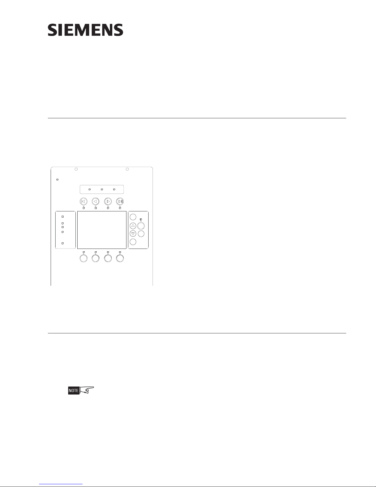
The FCM2041-U3 contains a full VGA LCD, Touch Screen and LEDs for
displaying system status. An audible sounds when there are unacknowledged events on the FCM2041-U3. The display is surrounded by
keys that are used to control the displayed information and to navigate
through these screens. Keys are also provided to obtain help and to
enter into the menu features of the FCM2041-U3. (Refer to Figure 1.)
POWER
AUDIBLES
ON
SILENCED
PART IAL
SYSTEM
DISABLED
CPU FAIL
ALARM
On the back of the FCM2041-U3 there are additional diagnostic displays
to aid in system troubleshooting. This is also where the FCM2041-U3
address is set and where the connection is made to Zeus for programming. (Refer to Figure 2.)
Figure 1
FCM2041-U3 User Interface
For systems configured to provide Smoke Control (UUKL), refer to the Cerberus PRO
Modular Manual, Document ID A6V11231627.
PRE-INSTALLATION Additional labels are available for applications that require French (Canadian), Spanish,
or Portuguese (Brazilian) languages. These labels need to be ordered separately.
Refer to the table below for ordering information.
To apply labels, remove the backing from the labels and apply them to the FCM2041U3. (Refer to Figure 3.)
For systems configured for Security, an LED must be configured (on an LCM-8) to
indicate Security. This LED must be present on each node in the system. Refer to the
Cerberus PRO Modular Manual, Document ID A6V11231627, and the Zeus Quick-Start
Manual, P/N 315-033875, for LCM-8 installation and configuration.
A6V11231630_en--_b
Building Building
Building
Building Building
Siemens Siemens
Siemens
Siemens Siemens
TT
ecec
hnologies Dihnologies Di
T
ec
hnologies Di
TT
ecec
hnologies Dihnologies Di
IndustryIndustry
Industry
IndustryIndustry
visionvision
vision
visionvision
,,
Inc. Inc.
,
Inc.
,,
Inc. Inc.
Page 2

001tenrehtespbM001afiydaetsswolgDEL
F
TCAtenrehtefosemitgnirudydaetsswolgDEL
TENHrofCPpotpalaotnoitcennocTENH
NALknilataddeepshgihrofdesutroptenrehtE
KNILsinoitcennoctenrehtenafiydaetsswolG
SNOITPO
TROPCCPoterawmrifwenrefsnartotde
TESER
1#DSIMPGerotsotdesutropdracDS
2#DSIMPGwollaotdesutropdracDS
SUTATSlamronetacidniotthgilstnemgesgniklaW
5-CCOT.5-CCotelbacnobbirnip-06stcennoC
MVLOT.suboiduago
A04-PST.retnirppirtsA04-PSTrofrotcennoC
DAOLPU
)"B"BSU(
BSU
"A"
DITENX;edomlacolni10otteS:sserddaT
SCITSONGAID3U-1402MCFFONOITPIRCSED
.detcetedsinoitcennoc
.ytivitca
krowten
.scitsongaidkrowten
.)sdao
lpuerawmrifUPCniamgnidulcni(
.detceted
noitpircseDniP
:
edomnoitarbilaCneercshcuoT-1
edoMdaolpUerawmriFUPCniaM-2
)DBT(-3
)DBT(-4
sutropBSU
.CCPeht
.
1
.IMPehtezilaitini-erotsserP
.teserdrahrofsdnoces5dloH.2
naesabatad
.noitamrofnipukcabd
.ytilibapac
idsiedocrorrE.noitarepo
nafideyalps
.detcetedsiDIrorrelanretni
EARTH
GND
lanA
gnirrefsnartroflootsueZotnoitcennoC
tadnoitarugifnocmetsys
eludomdnaa
.rotcennocBepytBSUsesU.erawmrif
noitamrofnidnasgoltcellocotdesutroP
.rotcennocAepytBSUsesU.metsysmorf
ENX
.TENXrofsserddaetairporppaottes
J7
HNET
J11
LAN
LINK
100
ACT
TO LVM
J1
SD #1
TO CC-5
J2
J5
PCC PORT
USB B
USB A
J16
J15
J18
SD #2
J19
XNET ID
UPLOAD
S2
S3
OPTIONS
ON
1234
S4
STATUS
TSP-40A
RESET
S1
J13
Figure 2
FCM2041-U3 Diagnostics
OR ALTERNATE
LANGUAGES,
APPLY
APPROPRIATE
LABEL HERE
FORALTERNATE
LANGUAGES,
APPLY
APPROPRIATE
LABEL HERE
POWER
AUDIBLES
ON
SILENCED
PARTIAL
SYSTEM
DISABLED
CPU FAIL
ALARM
SUPERVISORY
TROUBLE
MENU
?
Figure 3
Applying FCM2041-U3 Labels for Alternate Languages
More
Info
ESC
Part number S54430-C16A1 contains alternate
+
language labels
Siemens Industry, Inc.
Building Technologies Division
A6V11231630_en--_b2
Page 3
INSTALLATION
Remove ELECTRICAL POWER prior to installing the FCM2041-U3 in the enclosure.
Set the Network Address Remove the FCM2041-U3 from its anti-static bag. Set the two-digit address using
the 10-position rotary switches (S2, S3) located on the back of the FCM2041-U3. For
a standalone HNET panel, set the address of the FCM2041-U3 to 01. Be sure to set
leading zeros. In the Zeus Physical View, make sure that the FCM2041-U3 is configured at address 253.
When the FCM2041-U3 is used for networking with other panels, set the two-digit
network address to the XNET node address that has been assigned in Zeus. Be sure to
set leading zeros. For example, Node 2 is set at 02. In the Zeus Physical View, the
HNET address of the PMI is automatically set to 253 when operating in an XNET panel.
The table below details the differences between the network address settings in a
FCM2041-U3 and a PMI.
SEHCTIWSSSERDDAKROWTENEHTGNITTES
3U-1402MCF
N(TENX
yratoRforebmuN
sehctiwSsserddA
)enoladnatS(TENH
)IMPnognitteS(
)sueZnignitteS( taderugifnocsi3U-1402MCFehterusekaM
)krowte
)IMPnognitteS(
)sueZnignitteS(morf(sserddaedontigid-owtTENXehtteS
owT
)3S,2S(
.10otsserddateS
SnognittesoN
ssasserdda
.sorez
gnidaeltes
.)hctiwssnoitpO(4
.weivlacisyhpsueZehtni352sserdda
.)hctiwssnoitpO(4SnognittesoN
.sueZnitirofdengi
tigid-owtehtotsserddaedonTENXehtteS
oteruseB.eertlacisyhpsueZehtni)46-10
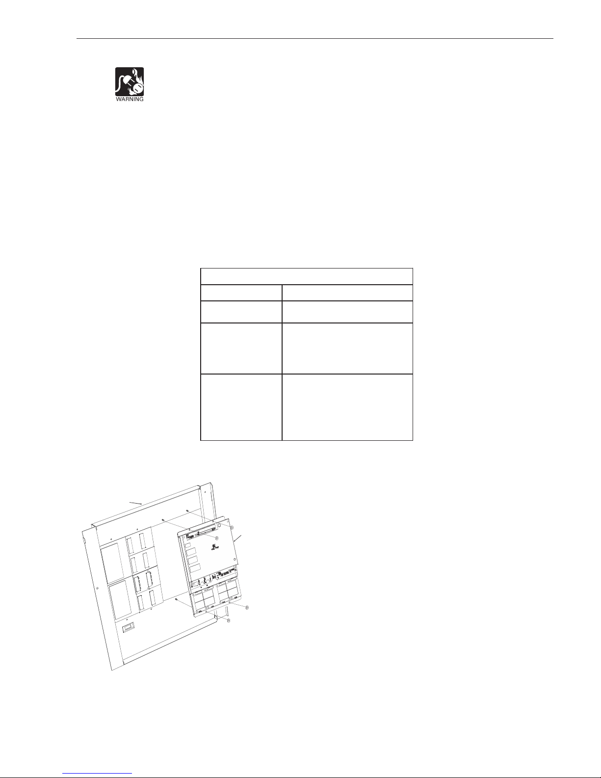
Mount the FCM2041-U3 The FCM2041-U3 mounts to the rear of the inner door in the CAB-1, CAB-2, CAB-3,
REMBOX2 or REMBOX4 enclosures. Select the location of the
FCM2041-U3. It can be mounted either in the center or on the left
INNER DOOR
side of the inner door, when viewed from the outside of the
enclosure. Place the FCM2041-U3 onto the inner door from the rear,
FCM2041-U3
over the four mounting studs in the desired location. Secure the
FCM2041-U3 to the inner door with the four nuts provided. (Refer to
Figure 4.)
A 40 inch long 60 wire cable, P/N 555-133743, connects the
FCM2041-U3 to the CC-5. The CC-5 is located in the back of the
enclosure on the left hand side. Connect one end of the cable to J2
on the FCM2041-U3. J2 is marked with “CC-5” on the FCM2041-U3
printed circuit board. Connect the other end of the cable to P1 on the
CC-5. (Refer to Figure 5.)
Connect the FCM2041-U3 to the RNI in a REMBOX2/4. The RNI is
located in the back of the enclosure on the top left hand side.
Figure 4
Mounting the FCM2041-U3 to
the Rear of the Inner Door
Siemens Industry, Inc.
Building Technologies Division
marked with “CC-5” on the printed circuit board. Connect the other
end of the cable to JP1 on the RNI. (Refer to Figure 6.)
Connect one end of the cable to J2 on the FCM2041-U3. J2 is
A6V11231630_en--_b3
Page 4

Figure 5
Connecting the FCM2041-U3 to the CC-5
Figure 6
Connecting the FCM2041-U3 to the RNI
Make sure that all cables snap fully into their connectors and close the locking levers
over the top of each cable connector. Secure the cable in the back box using cable
ties and the tie down points in the enclosure. The cable must have sufficient slack to
allow the inner door to open fully without putting stress on the cable.
OPERATION In the normal standby condition the FCM2041-U3 displays the site specific custom
message, the time and date, and a synopsis of the system status.
When an event occurs in the system, the display enters the Alert mode. The event is
displayed, the local audible sounds and the tab on the display for the corresponding
event queue flashes. If the event type is Alarm, Trouble, or Supervisory, the appropriate
LED blinks. If the event caused notification appliances to sound the Audibles On
indicator lights. At the bottom of the screen an acknowledge button is displayed.
Pressing this button acknowledges the event and silences the local audible. Once all
events are acknowledged a reset button becomes available in the lower right side of
the display. If notification appliances were active, two additional buttons appear at the
bottom of the screen. These allow the operator to silence or unsilence the notification
appliances. When the notification appliances are silenced the Audibles Silenced LED
lights. The system can only be reset with the notification appliances silenced.
If more events are present in the system than can be displayed on a single screen a
scroll bar appears to the right of the event list. Pressing the up and down navigation
buttons to the right of the LCD allows the operator to move through the list. The
selected event is highlighted in the display. Pressing the More Info button will display
a screen showing details relating to the selected event. Other buttons also appear at
the bottom of this screen. There is an expanded text message available and a
selection to show all of the devices associated with the event that are active. The
operator can return to the previous screen by pressing the ESC button. (For more
detail on FCM2041-U3 operation, refer to the Cerberus PRO Modular Manual,
Document ID A6V11231627.)
If the LED under one of the
button moves the highlight to the next queue. Use the
Siemens Industry, Inc.
Building Technologies Division
the first or last queue.
buttons above the LCD is lit, pressing the
buttons to shift to
A6V11231630_en--_b4
Page 5

TO UPGRADE FROM Follow the procedure below to upgrade an Cerberus PRO Modular panel from a
PMI TO FCM2041-U3 PMI to a FCM2041-U3.
1. Please ensure you are using Zeus-C, 1.0 or greater.
2. Create a new project in Zeus (File>New) to avoid overwriting a current
project. The new project’s filename is not important.
3. Download the current configuration from the PMI.
a) Connect the Laptop via the Upload cable and select
Build>Transfer>Configuration From Panel.
b) An .hrc configuration file from the PMI control panel downloads to the
Zeus host PC. Initially, the Zeus Transfer dialog will open, with settings for
serial port and transfer protocol. Once these are set, the Transfer Configuration dialog will display information the PMI’s current configuration,
software and firmware versions. You can select the panel from which to
download (if there are multiple compiled configurations in the host PC),
and also choose to download the PMI’s current history file into the
project directory. Once you have begun the transfer, the Transfer
Progress dialog displays transfer progress and status messages, and
allows you to cancel the transfer.
4. Once the panel configuration is downloaded, close the new project, use
Tools > Decompile to open the downloaded .hrc configuration file as a
project in Zeus.
5. In the Zeus tool replace the PMI with the new FCM2041-U3.
Please make sure you are converting the correct PMI with a FCM2041-U3 by matching the address of the switches on the back of the PMI.
a) In the configuration which you have just removed from the original PMI,
click on the PMI module in the physical tree. Select the Edit menu and
click on “Find/Replace Tree Node”. A dialog box will open and allow you
to replace the PMI with the FCM2041-U3.
b) Once this is completed, save and then compile the configuration.
Remove ELECTRICAL POWER prior to removing the original PMI and installing the
new FCM2041-U3 in the enclosure.
c) Physically remove the original PMI and install the new FCM2041-U3 on
the inner door of the enclosure. (For more detail see the INSTALLATION
section and Figure 4 of this document.)
d) Re-attach the 60-pin cable to the connector at the top of the FCM2041-
U3 (see Figures 5 and 6) as well as any other original connections to the
PMI.
e) Apply power and allow the unit to initialize.
6. Transfer the configuration to the Panel.
a) Connect the USB programming cable to the FCM2041-U3 USB type B
connector labeled “UPLOAD” at the bottom of the unit. (Refer to Figure
2.)
b) In the Zeus configuration, select the module in the Physical Tree. Then
select Build>Transfer>Configuration to Panel. An .hrc configuration file
uploads from the Zeus host PC to the FCM2041-U3 control panel,
overwriting the existing configuration in the panel.
i) Initially, the Zeus Transfer dialog will open, with settings for serial port
and transfer protocol. Once these settings are made, the Transfer
Siemens Industry, Inc.
Building Technologies Division
A6V11231630_en--_b5
Page 6

Configuration dialog will display information on the PMI firmware and
system configuration currently stored in the panel. You can select the
configuration to upload (if there are multiple compiled configurations
in the host PC), and also choose to download the PMI’s current
history file into the project directory.
ii) Once you have begun the transfer, the Transfer Progress dialog
displays transfer progress and status messages, and allows you to
cancel the transfer. When you click OK at the transfer complete
message, the control panel will reset itself with the new configuration.
ELECTRICAL RATINGS
rewoPtupnIrewoPtuptuO
tnerruCenalPkcaBV42Am591
nimreTwercS0
tnerruCV42la
tnerruCenalPkcaBV2.60
tnerruCybdnatSV42Am521
dnaTENX/TENHhcaE
riaPkrowteNNAC
.xamkaepotkaepV8
.gsmgnirud(.xamAm57
)noissimsnart
Siemens Industry, Inc.
Building Technologies Division
A6V11231630_en--_b6
Page 7

Cyber security disclaimer
Siemens products and solutions provide security functions to ensure the secure operation of
building comfort, fire safety, security management and physical security systems. The security
functions on these products and solutions are important components of a comprehensive security
concept.
It is, however, necessary to implement and maintain a comprehensive, state-of-the-art security
concept that is customized to individual security needs. Such a security concept may result in
additional site-specific preventive action to ensure that the building comfort, fire safety, security
management or physical security system for your site are operated in a secure manner. These
measures may include, but are not limited to, separating networks, physically protecting system
components, user awareness programs, defense in depth, etc.
For additional information on building technology security and our offerings, contact your Siemens
sales or project department. We strongly recommend customers to follow our security advisories,
which provide information on the latest security threats, patches and other mitigation measures.
http://www.siemens.com/cert/en/cert-security-advisories.htm
Siemens Industry, Inc.
Building Technologies Division
A6V11231630_en--_b7
Page 8

This page has been left intentionally blank.
Siemens Industry, Inc.
Building Technologies Division
Florham Park, NJ
Siemens Canada, Ltd.
1577 North Service Road East
Oakville, Ontario
L6H 0H6 Canada
P/N A5Q00075185
Document ID A6V11231630_en--_b
 Loading...