

Page 1

FC2005/FC901
System installation instruction
Wiring diagram
Software clearance declaration
FC901 FC2005
Building Technologies
Fir e Safety & S ecuri ty Prod uct s
Page 2

FC2005/FC901 installation instruction
Accessories and separate parts
Accessory
items
1
2
3
4
5
6
7
8
9
Content Installation instruction Qty
Cable between batteries, refer to figure 1 1
1.1
2.1
2.2
3.1
4.1
5.1
1.2
Cable between batteries and main board, refer to figure 1,figure 2
2.3
3.2
3.3
Cable between City tie board and main board, refer to figure 2
Earth cable between enclosure and main board, refer to figure 1 and
4.2
figure 2
Grounding cable for front door and power supply,
5.2
refer to figure 1
Battery bracket left, refer to figure 1
Battery bracket right, refer to figure 1
Cable ties
No.8 screws, refer to figure 1
1
1
1
2
1
1
10
12
10
11
12
S1
S2
S3
S4
S5
Note: Item 3,6,7,11,S1and S2 are not delivered with the FC901 and FC2005.And should be ordered separately.
Assembling notes
1. Mount the batteries with battery brackets.
2. Mount the power supply MOV, then mount the power supply to the enclosure.
3. Mount the City tie module onto the main board according to the Figure 2 (City tie module is optional).
4. Connect the cables to the corresponding position marked on the drawing
(The power supply input cable and output cable are not included in the FC901 and FC2005 package).
4. Tie the cables to the enclosure with cable tie, refer to the Figure 1(Cable tie features).
5. Mount the Main board assembly onto the Enclosure according to Figure 3.
6. Mount the Lock pin to the Front door axis(Both are included in the Enclosure package)
Build in g Technol og ie s
Fire Sa fe ty & S ecurity P ro ducts
No.4 screws, refer to figure 2
Spacer for City tie board, refer to figure 2
Power supply MOV(Metal Oxide Varistor), refer to figure 2
Battery cell, refer to figure 1
Power supply, refer to power supply installation instruction sheet
delivered with power supply
Front door hinge axis lock pin, refer to Detail A
Front door hinge axis, refer to Detail A
EOL for NAC, refer to Detail C
Docum en t ID : A5Q00039 71 3A
Page 1/ 12 02.20 12
2
2
1
2
1
2
2
2
FC200 5/ FC 901 insta ll ation ins tr uction
Page 3

FC2005/FC901 installation instruction
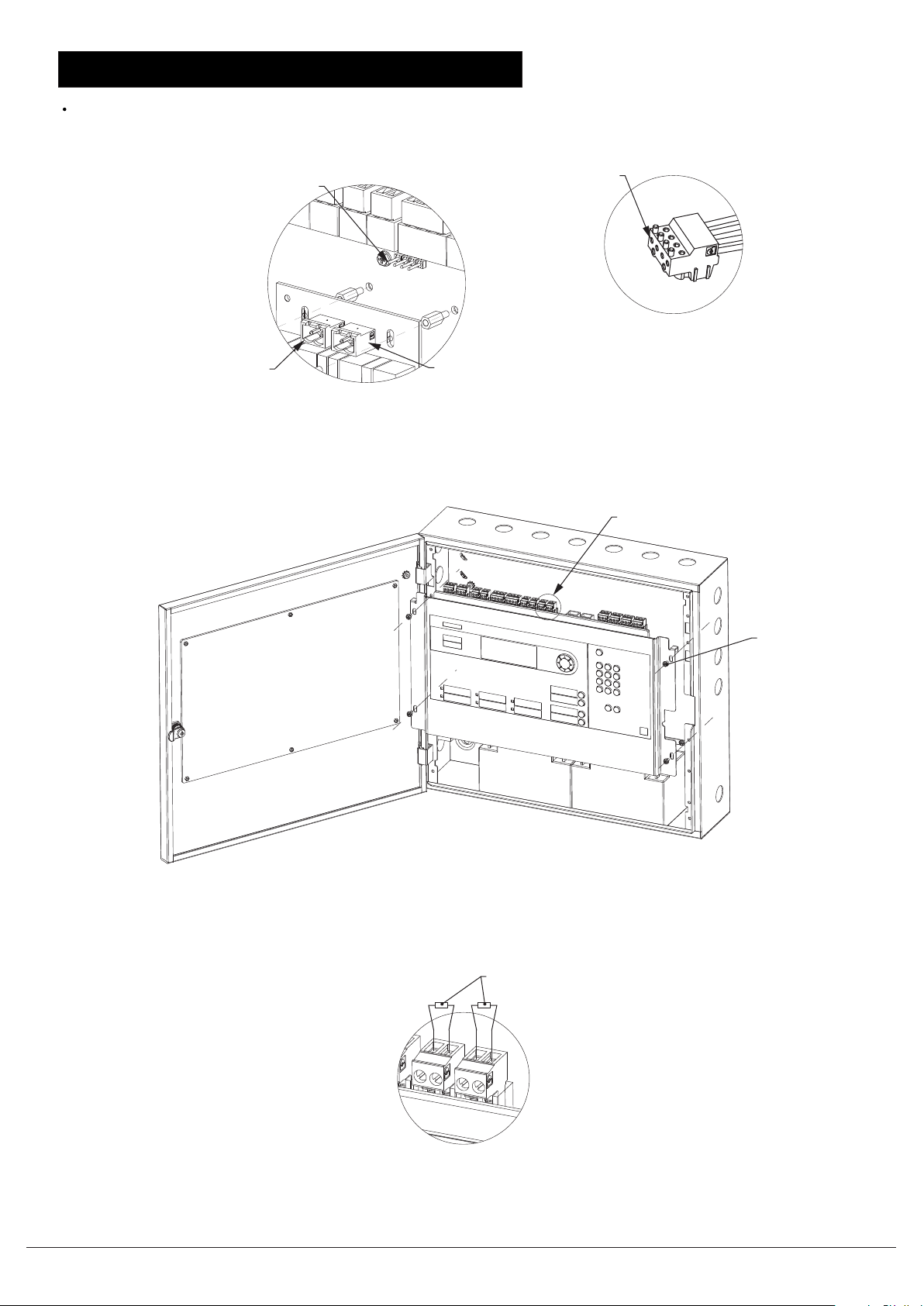
Battery, Power supply and City tie PCB assembly installation instruction
Pay attention to the battery polarity at 2.1 and 2.2
Detail A
5.2(1)
4.1 and 5.1(1)
5.1(2)
Power supply
DC output
Cable tie feature
Brownout
GNDGND +26
S2
1.1 1.22.1 2.2
6
Figure 1 Installation instruction(Front view with front door open)
5.2(2)
9
7
S1
S3
Detail A Front door hinge and lock pin installation instruction
11
3.1
10
City tie
module
3.2
3.3
2.3
Power supply DC input
Detail B
4.2
Build in g Technol og ie s
Fire Sa fe ty & S ecurity P ro ducts
Figure 2 Installation instruction(Main board assembly back view)
Docum en t ID : A5Q00039 71 3A
Page 2/ 12 02.20 12
FC200 5/ FC 901 insta ll ation ins tr uction
Page 4
FC2005/FC901 installation instruction
City tie cable,Main board and EOL installation instruction
From left to right:
TP1295,TP1294,TP1293,TP1292
X2 Output 2
Connect to 3.2
Detail B City tie cabling
From 1 to 4
TP1295,TP1294,TP1293,TP1292
X3 Output 1
Connect to 3.3
1
Detail C
2
3
4
3.1
Figure 3 Main board assembly installation instruction
S5
9
Build in g Technol og ie s
Fire Sa fe ty & S ecurity P ro ducts
N_BN
N_BP
-
+
N_AN
N_AP
-
+
Detail C NAC EOL installation instruction
Docum en t ID : A5Q00039 71 3A
Page 3/ 12 02.20 12
FC200 5/ FC 901 insta ll ation ins tr uction
Page 5

FC2005/FC901 installation instruction
Power supply MOV(Metal Oxide Varistor) Installation instruction
Step 1: Bend the MOV connector pin
refer to the picture for an example
Step 2: Fix or weld the MOV onto the power input
connector.Take the picture as reference
Step 3: Fix the AC input cable and screws on
the connector. Take the picture as reference
Build in g Technol og ie s
Fire Sa fe ty & S ecurity P ro ducts
Docum en t ID : A5Q00039 71 3A
Page 4/ 12 02.20 12
FC200 5/ FC 901 insta ll ation ins tr uction
Page 6

FC2005/FC901 installation instruction
Installation instruction without Trim kit
5 7/64”
Cerberus
18 1/8”
TM
16 ½”
8 1/4”
Mount Control Unit at
a convenient height
for access to display
and controls
Build in g Technol og ie s
Fire Sa fe ty & S ecurity P ro ducts
Docum en t ID : A5Q00039 71 3A
Page 5/ 12 02.20 12
FC200 5/ FC 901 insta ll ation ins tr uction
Page 7

FC2005/FC901 installation instruction
Installation instruction with Trim kit
21 1/4”
TM
Cerberus
4 1/4” MAX
19 5/8”
8 1/4”
Mount Control Unit at
a convenient height
for access to display
and controls
Build in g Technol og ie s
Fire Sa fe ty & S ecurity P ro ducts
Docum en t ID : A5Q00039 71 3A
Page 6/ 12 02.20 12
FC200 5/ FC 901 insta ll ation ins tr uction
Page 8

FC2005/FC901 SYSTEM CONNECTION DIAGRAM
Environm ental SLC Addr e ssable Device Circuits
Operating temperature - 32 - 120°F (0 - 49°C) 32 VDC Max
Relative humidity - Up to 93% @ 90°F (32°C) Pow er limited
To be installed in a indoor dry protected environment only Supervised
Max. current: 0.07A(RMS)
Prim ary Pow er Supply Maximum w ire loop resistance: 50Ω
Input: 120VAC, 60 Hz or 220 VAC, 50 Hz Tw o Style 4 Class B or one Style 6 Class A circuit
@ 2.0A Max. Max. 50 addressable devices
Supervised City Tie Circuits
Output: 26VDC @ 6.5A Max. Supply Input:
Max current: 6.5A (2 hours Max.) Voltage: 26 VDC
Filtered and Regulated 18 – 28 VDC for battery
Current: Max . 0.4A
Secondary Pow er Supply Supervised
24V lead-acid battery set Output:
Max. charged voltage: 27.8 VDC City Tie -Output 1
Automatic low battery disconnect voltage: 19.2±0.1VDC Normal output voltage: 19-28VDC (open circuit condition)
Max. charge current: 0.45A Supervisory current: 1mA
Battery capacity:12AH to 18AH Maximum trip current: 400mA
Supervised Maximum coil plus w ire resistance: 22.5Ω
Auxiliary Power Outputs Leased line-Output 1
- Non-res e ttable pow e r output Normal output voltage:19-28VDC (open circuit condition)
Pow er limited Trouble output voltage: 0V
Alarm status: 0.75A
Alarm output voltage:-(19-28)V DC (open circuit condition)
Normal stand by: 0.05A Maximum w ire resistance: 2-5KΩ
Voltage: 19 to 28VDC Maximum short circ uit current: 25mA
Ripple: 0.1 VAC
Special Application Leased line-Output 2
Normal output voltage: 19-28VDC (open circuit condition)
- Resettable pow er output Supervisory output voltage: -(19-28)VDC (open circuit condition)
Pow er limited Maximum w ire resistance: 2-5KΩ
Alarm status: 0.75A Maximum short circ uit current: 25mA
Normal stand by: 0.05A
Voltage: 19 to 28VDC DACT Circuits
Ripple: 0.1 VAC Pow er limited
Special Application Supervised for short or open circuit conditions
Compliance to FCC part 68
Status Relays Support RJ31X connection
Non-pow er limited Compatible Digital Alarm Communication Receiver (DACR) list,
One programmable relay
Three non-programmable relays: Trouble, Supervisory, Alarm
Contact rating: 2A, 30VDC maximum
Form C contact
Notification Appliance Circuits
Pow er limited
Supervised
Current Draw Maximum Line Resistance
2.5A 3.2Ω
2.0A 4.0Ω
1.5A 5.3Ω
1.0A 8.0Ω
0.5A 16.0Ω
Alarm voltage: 16 to 32VDC
Maximum ripple: 0.1VAC
Used for special application only
Tw o Style Y/Class B or one Style Z/Class A
Total Max. Current: 2.5A
Device m odule Manufactu re
MX8000 Honeyw ell
DACT compatibility list
FC2005/FC901 SYSTEM GENERAL SPECIFICATION
Build in g Technol og ie s
Fire Sa fe ty & S ecurity P ro ducts
CAUTION – To reduce the risk of fire, use only No. 26 AWG
or larger telecommunication line cord.
Docum en t ID : A5Q00039 71 3A
Page 7/ 12 02.20 12
FC200 5/ FC 901 insta ll ation ins tr uction
Page 9

FC2005/FC901 SYSTEM CONNECTION DIAGRAM
FC2005/FC901 SYSTEM CONNECTION DIAGRAM
T_NC
T_CO
T_NO
A_NO
A_CO
A_NC
U_NO
U_CO
U_NC
S_NO
S_CO
S_NC
PORT1
DACT
USB type B plug
DACT Relays
Circuits(NAC)
Notification Application
City tie or
lease line
PORT2
DACT
Battery connector
12AH - 18AH@24VDC
Supervised, Non power limited
N_AP
N_AN
N_BP
N_BN
LL_SP
LL_SN
CT_P
CT_N
EARTH
PR_B
PR_A
GND1
EARTH
SE_B
SE_A
GND1
X1_P
X1_N
X2_P
X2_N
S_AP
S_AN
EARTH
SLC loop Auxiliary power Series interface circuit
S_BP
S_BN
EARTH
Note: All the wiring must be in according with local codes and National Electric Code.
Build in g Technol og ie s
Fire Sa fe ty & S ecurity P ro ducts
Docum en t ID : A5Q00039 71 3A
Page 8/ 12 02.20 12
FC200 5/ FC 901 insta ll ation ins tr uction
DC power input
6.5A@26VDC
Page 10

FC2005/FC901 SYSTEM CONNECTION DIAGRAM
FC2005/FC901 SYSTEM CONNECTION DIAGRAM
SLC loop connections
Supervised and power limited, detail device compatibility list refer to user manual Appendix B
Class A
Class B
50 max devices
...
...
...
50 max devices
Note: The earth gets connected to the
shield (if used)
EARTH
S_BN
S_BP
EARTH
0.07A@6-32 VDC
S_AN
S_AP
Note: The earth gets connected
to the shield (if used)
0.07A@6-32 VDC
EARTH
S_BN
S_BP
EARTH
0.07A@6-32 VDC
S_AN
S_AP
Auxiliary power
Non supervised and power limited
Auxiliary power output 2
(Resettable, power limited)
Conventional detectors
Auxiliary power output 1
(Non-resettable, power limited)
+
-
Alarm 0.75A @19-28VDC
Normal 0.05A @19-28VDC
X2_N
Max. current= 0.75A
X2_P
-
applicance
Power -
Alarm 0.75A @19-28VDC
Normal 0.05A @19-28VDC
X1_N
24V
+
Power +
Max. current= 0.75A
X1_P
Build in g Technol og ie s
Fire Sa fe ty & S ecurity P ro ducts
Docum en t ID : A5Q00039 71 3A
Page 9/ 12 02.20 12
FC200 5/ FC 901 insta ll ation ins tr uction
Page 11

100mA@2 6V DC Act ive (19-2 8V DC on Bat tery)
Polarit y Reversing Circuit
+26V DC Nor mal (OUTPUT 1 and OUTPUT 2)
-26 VDC Alarm (OUTPUT 1)
0V Troubl e (OUTPUT 1)
-26 VDC Supervisory (OUTPUT 2 )
External Circuit Resist ance 2K-5K ohms
M unicipal Tie Volt age 350mA@2 6V DC Act ive(19-2 8V DC on Battery)
+26V DC Nor mal & 1mA Supervisory Current
350mA Al arm@+26V DC
M unicipal Tie Trip Co il 14.5 ohms
M unicipal Tie Supervisor y Current 1mA
C it y t ie and l ea se d l ine rat ing
Leased Line Vo lt age Rati ng
FC2005/FC901 SYSTEM CONNECTION DIAGRAM
FC2005/FC901 SYSTEM CONNECTION DIAGRAM
Series Interface Circuit
Power limited
FSD
...
City tie or lease line
power limited
Master box
FSD
Used for Class A wiring
(Reserved)
SE_B
SE_A
GND1
Output 2Output 1
Connected to shield(if used)
EARTH
FSD
(Reserved)
EARTH
PR_B
PR_A
GND1
8 FSD max
Connected to shield(if used)
CT_P
CT_N
LL_SP
LL_SN
Notification Application Circuits
Supervised, power limited, Max. current(NAC A+NAC B)=2.5A
Build in g Technol og ie s
Fire Sa fe ty & S ecurity P ro ducts
N_BP
N_BN
Docum en t ID : A5Q00039 71 3A
Page 10 /1 2 02.2 01 2
N_AP
N_AN
FC200 5/ FC 901 insta ll ation ins tr uction
Page 12

Device m odule Manufacture
MX8000 Honeyw ell
DACT compatibility list
FC2005/FC901 SYSTEM CONNECTION DIAGRAM
FC2005/FC901 SYSTEM CONNECTION DIAGRAM
DACT
Power limited
(Primary Lines Incoming Telco Phone Lines)
Ring
Tip
To premises phones
1 2 3 4 5 6 7 8
RJ31-X
Jack
Secondary Phone line
PORT2
DACT
Ring
Tip
(Secondary Lines Incoming Telco Phone Lines)
Ring
Tip
1 2 3 4 5 6 7 8
RJ31-X
Jack
Primary Phone line
PORT1
DACT
Ring
To premises phones
Tip
Relays
Non power limited, 2.0A@30VDC(Resistive), 0.5A@30VAC(Resistive)
Supervisory relay
Dry contact
S_CO
S_NC
User defined relay
Dry contact
S_NO
U_NO
U_CO
U_NC
Alarm relay
Dry contact
A_CO
A_NC
Trouble relay
Dry contact
A_NO
T_NC
T_NO
T_CO
Sieme ns I nd ustry, Inc .
Build in g Technol og ie s Divisio n
Florh am P ar k, NJ 07932
Build in g Technol og ie s
Fire Sa fe ty & S ecurity P ro ducts
Docum en t ID : A5Q00039 71 3A
Page 11/ 12 02. 20 12
FC200 5/ FC 901 insta ll ation ins tr uction
 Loading...