

Page 1

FC7xx / FT724
Building Technologies
Fire control panel / fire terminal
Operation Manual
IP6
A6V10211076_i_en_--
2015-12-15 Control Products and Systems
Page 2

Legal notice
Building Technologies
A6V10211076_i_en_
--
Fire Safety
2015-12-
15
Legal notice
Technical specifications and availability subject to change without notice.
Transmittal, reproduction, dissemination and/or editing of this document as well as
utilization of its contents and communication thereof to others without express
authorization are prohibited. Offenders will be held liable for payment of damages.
All rights created by patent grant or registration of a utility model or design patent
are reserved.
Issued by:
Siemens Switzerland Ltd.
Building Technologies Division
International Headquarters
Gubelstrasse 22
CH-6301 Zug
Tel. +41 41 724-2424
www.siemens.com/buildingtechnologies
Edition: 2015-12-15
Document ID: A6V10211076_i_en_--
© Siemens Switzerland Ltd, 2008
2 | 184
Page 3

Building Technologies
A6V10211076_i_en_
--
Fire Safety
2015-12-
15
Table of contents
1 About this document ............................................................................. 9
1.1 Applicable documents ................................................................................10
1.2 Technical terms and abbreviations .............................................................10
1.3 Revision history .........................................................................................11
1.4 How displays are represented in the document ..........................................13
1.5 Download center ........................................................................................13
2 Safety ............................................................................................... 14
2.1 Safety instructions .....................................................................................14
2.2 Safety regulations for the method of operation ...........................................16
2.3 Standards and directives complied with......................................................18
2.4 Release Notes ...........................................................................................18
2.5 Cyber security disclaimer ...........................................................................18
3 Setup of the Person Machine Interface .................................................. 19
3.1 PMI............................................................................................................19
3.1.1 EVAC NL ....................................................................................21
3.1.2 Key switch (optional) ...................................................................22
3.1.3 Standard keys .............................................................................22
3.1.4 Other alarms ...............................................................................23
3.2 Person Machine Interface with FBP [AU]....................................................23
3.3 Display ......................................................................................................26
3.3.1 Normal view ................................................................................26
3.3.2 Extended view ............................................................................27
3.3.3 Fire brigade view.........................................................................27
3.3.4 Display with window and list ........................................................27
3.3.5 Display with window and input field .............................................28
3.3.6 Display with window and command response ..............................28
3.4 Soft keys ...................................................................................................29
3.5 Navigation buttons .....................................................................................30
3.6 Keypad ......................................................................................................30
3.6.1 Menu button ................................................................................31
3.6.2 Button 'ok' ...................................................................................31
3.6.3 Button 'C' ....................................................................................31
3.7 LEDs .........................................................................................................31
3.8 Menu structure...........................................................................................32
3.9 Cerberus Remote ......................................................................................33
3.10 Cerberus Mobile ........................................................................................34
4 Operation functions............................................................................. 35
4.1 Selection and opening / execution ..............................................................35
4.2 Scrolling ....................................................................................................35
4.3 Indication of the position and length of the list ............................................36
4.4 Shortcut .....................................................................................................36
4.5 Favorites ...................................................................................................36
3 | 184
Page 4

Building Technologies
A6V10211076_i_en_
--
Fire Safety
2015-12-15
4.6 Entry of numbers and letters ...................................................................... 37
4.7 Cerberus Remote operation modes ........................................................... 38
4.8 Cerberus Mobile operation modes ............................................................. 39
5 Operation ...........................................................................................40
5.1 ALARM Procedure ..................................................................................... 40
5.2 ALARM procedure PMI with FBP [AU] ....................................................... 42
5.3 Procedure in case of Fault ......................................................................... 44
5.4 Switching off / Switching on ....................................................................... 45
5.4.1 Switching a detector zone off / on................................................ 45
5.4.2 Switching a detector off / on ........................................................ 48
5.4.3 Temporary switching-off .............................................................. 51
5.4.4 Switching off / on the remote transmission Fire ........................... 53
5.4.5 Switching off alarm activation ...................................................... 57
5.4.6 Switching off sabotage evaluation [DE] ....................................... 57
5.5 Log in / Change access level ..................................................................... 58
5.6 Logging out from an access level ............................................................... 58
5.7 Switching between 'Manned' / 'Unmanned' operation modes ...................... 59
5.8 Changing visibility ...................................................................................... 60
5.8.1 Deactivating standby ................................................................... 60
5.8.2 Activating / deactivating expanded visibility ................................. 61
5.9 Main menu / Open menu item .................................................................... 62
5.10 Execute commands – Basics ..................................................................... 62
5.10.1 Execute commands – General .................................................... 63
5.10.2 Execute commands – object-oriented .......................................... 64
5.10.3 Executing commands – function-oriented .................................... 66
5.10.4 Hide command confirmation message ......................................... 67
5.11 Selecting elements or events ..................................................................... 68
5.11.1 Select events .............................................................................. 68
5.11.2 Selection in the topology ............................................................. 69
5.11.3 Searching for elements ............................................................... 71
5.12 Testing ...................................................................................................... 74
5.12.1 Testing detectors ........................................................................ 74
5.12.2 Carrying out an installation test ................................................... 75
5.12.3 Carrying out the walk test ............................................................ 75
5.12.4 Control test ................................................................................. 76
5.12.5 Testing indicators ........................................................................ 77
5.13 Activation / Deactivation / Reset ................................................................. 78
5.13.1 Activating an alarm indicator (AI) ................................................. 78
5.13.2 Deactivating / Activating alarm devices ....................................... 81
5.13.3 Activating / resetting zone ........................................................... 82
5.13.4 Activating / deactivating fire control ............................................. 85
5.13.5 Activating evac controls .............................................................. 87
5.14 Show information ....................................................................................... 89
5.14.1 Polling alarm counters / remote transmissions ............................. 89
5.14.2 Polling the IP address of the 'Station' .......................................... 90
5.15 Polling reports ........................................................................................... 91
4 | 184
Page 5

Building Technologies
A6V10211076_i_en_
--
Fire Safety
2015-12-
15
5.16 Entering the configuration ..........................................................................92
5.17 Auto-configure station ................................................................................93
5.18 Auto-configure line .....................................................................................94
5.19 Enabling / Disabling Cerberus Remote .......................................................96
5.20 Connecting Cerberus Remote ....................................................................98
5.21 Setting up Cerberus Remote link with integrated IP ....................................99
5.22 Operating Cerberus Remote ......................................................................99
5.23 Specifying the operation mode for Cerberus Mobile .................................100
5.24 Enabling a smartphone ............................................................................100
5.25 Removing a smartphone ..........................................................................101
5.26 Polling / Deleting the event memory .........................................................102
5.27 Settings / Administration ..........................................................................103
5.27.1 Change language......................................................................103
5.27.2 PIN administration .....................................................................104
5.27.3 Setting the buzzer sound level ..................................................105
5.27.4 Adjusting the display brightness ................................................106
5.27.5 Setting time and date ................................................................106
5.28 Entering/Changing customer text .............................................................107
5.29 Insert printing paper .................................................................................107
5.30 Switching off the printer ...........................................................................110
5.31 Show version ...........................................................................................110
6 System functions .............................................................................. 111
6.1 Note on the configuration of the local fire detection installation .................111
6.2 Operating condition ..................................................................................112
6.3 Operation modes .....................................................................................112
6.3.1 Normal operation ......................................................................112
6.3.2 Isolation ....................................................................................113
6.3.3 Renovation ...............................................................................113
6.4 Normal operation .....................................................................................113
6.5 Test .........................................................................................................114
6.5.1 Detector test .............................................................................114
6.5.2 Installation test ..........................................................................114
6.5.3 Walk test ...................................................................................115
6.5.4 Control test ...............................................................................115
6.5.5 Test variants .............................................................................115
6.6 Isolation ...................................................................................................116
6.7 Renovation ..............................................................................................116
6.8 Access level and access rights ................................................................116
6.8.1 PIN input dialog ........................................................................118
6.8.2 Logout timeout ..........................................................................118
6.9 Visibility ...................................................................................................118
6.9.1 Standby visibility .......................................................................119
6.9.2 Expanded visibility ....................................................................119
7 Commands with required access levels ............................................... 120
7.1 'Switching on/off' command group ............................................................120
7.2 Command zone 'Test' ..............................................................................121
5 | 184
Page 6

Building Technologies
A6V10211076_i_en_
--
Fire Safety
2015-12-15
7.3 'Activating/deactivating' command group .................................................. 123
7.4 Command group 'Information' .................................................................. 124
7.5 'Configuration' command group ................................................................ 124
7.6 'Maintenance' command group ................................................................ 125
7.7 'Report' command group .......................................................................... 126
7.8 Other commands ..................................................................................... 126
8 List of elements ................................................................................ 127
9 System description ............................................................................ 129
9.1 Overview ................................................................................................. 129
9.2 Topology ................................................................................................. 131
9.2.1 Hardware tree ........................................................................... 131
9.2.2 Detection tree ........................................................................... 132
9.2.3 Control tree ............................................................................... 136
9.2.4 Operating tree ........................................................................... 138
9.2.5 Network tree ............................................................................. 140
9.2.6 Assigning with the hardware tree............................................... 141
9.2.7 Functional allocation ................................................................. 142
9.3 Acquisition ............................................................................................... 143
9.4 Evaluation ............................................................................................... 144
9.5 Control .................................................................................................... 148
9.5.1 Fire control................................................................................ 149
9.5.2 Evacuation control .................................................................... 150
9.5.3 Extinguishing control with sprinkler ............................................ 152
9.5.4 Extinguishing control with extinguishing control unit XC10 ......... 153
9.5.5 Damper control ......................................................................... 154
9.6 Alarm verification concept (AVC) ............................................................. 158
9.6.1 Attendance check ..................................................................... 159
9.6.2 Investigation time ...................................................................... 159
9.6.3 Example of a verification process .............................................. 159
9.6.4 Fire alarming ............................................................................. 161
9.7 Intervention concept (IC) .......................................................................... 163
9.7.1 Attendance check ..................................................................... 165
9.7.2 Intervention monitoring.............................................................. 165
9.7.3 Example of an intervention process ........................................... 165
9.7.4 Intervention alarming ................................................................ 167
9.8 Events ..................................................................................................... 168
9.8.1 Event categories ....................................................................... 168
9.8.2 Event status identification.......................................................... 169
9.8.3 Event memory .......................................................................... 169
9.8.4 Message overview .................................................................... 170
9.9 List representation and list types .............................................................. 171
9.9.1 Event lists ................................................................................. 171
9.9.2 Element lists ............................................................................. 172
9.9.3 Selection lists ............................................................................ 172
9.10 Version display for station / configuration data ......................................... 173
6 | 184
Page 7

Building Technologies
A6V10211076_i_en_
--
Fire Safety
2015-12-
15
10 Faults / Troubleshooting .................................................................... 174
11 System maintenance ........................................................................ 175
11.1 Maintenance recommendation .................................................................175
11.2 Opening the control panel [DE] ................................................................175
Glossary ................................................................................................... 176
Index ...................................................................................................... 179
7 | 184
Page 8

Building Technologies
A6V10211076_i_en_
--
Fire Safety
2015-12-15
8 | 184
Page 9

A
bout this document
Applicable documents
184
A6V10211076_i_en_
--
Fire Safety
2015-12-15
1 About this document
Goal and purpose
This document describes the operation of fire control panels and fire terminals in
the fire detection system FS720. The reader shall understand the structure of a fire
detection installation, the PMI setup and the functions in the overall system. This
understanding makes an adequate behaviour possible in the event of fire or fault.
Scope
The document applies to the fire control panels and the fire terminal of type Fx72x,
introduction package IP6.
Target groups
The information in this document is intended for the following target groups:
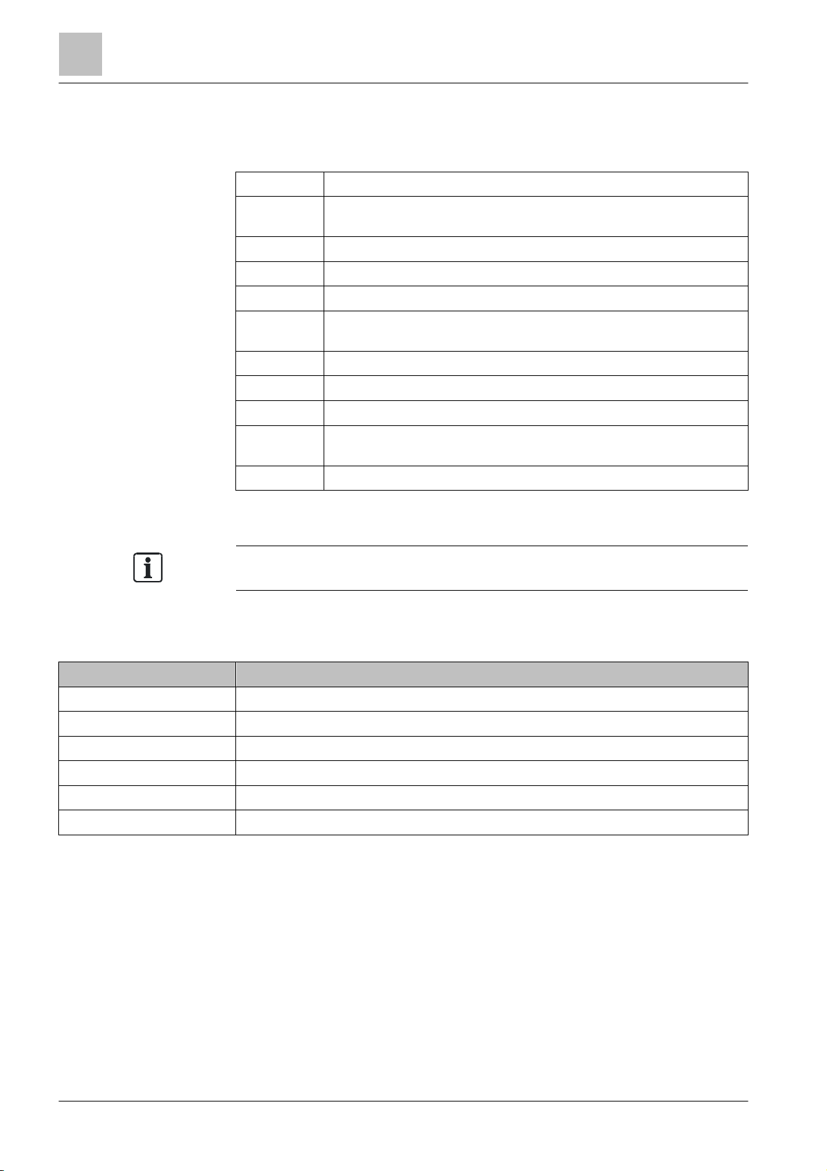
Target group Activity Qualification
1
Operating personnel
Commissioning personnel
Maintenance personnel ● Carries out all maintenance work.
● Carries out procedures to correctly
operate the product.
● Configure the product at the place
of installation according to
customer-specific requirements.
● Check the product operability and
release the product for use by the
operator.
● Searches for and corrects
malfunctions.
● Checks that the products are in
perfect working order.
● Searches for and corrects
malfunctions.
Source language and reference document
● The source/original language of this document is German (de).
● The reference version of this document is the international version in English.
The international version is not localized.
● No particular basic training is
needed.
● Has been instructed by the
commissioning personnel.
● Has obtained suitable specialist
training for the function and for the
products.
● Has attended the training courses
for commissioning personnel.
● Has obtained suitable specialist
training for the function and for the
products.
Building Technologies
Document identification
The document ID is structured as follows:
ID code Examples
ID_ModificationIndex_Language_COUNTRY
-- = multilingual or international
A6V10215123_a_de_DE
A6V10215123_a_en_-A6V10315123_a_--_--
Date format
The date format in the document corresponds to the recommendation of
international standard ISO 8601 (format YYYY-MM-DD).
9 |
Page 10
About this document
Applicable documents
1
Building Technologies
A6V10211076_i_en_
--
Fire Safety
2015-12-15
The 'i' symbol identifies supplementary information and tips for an easier way of
Conventions for text marking
Markups
Special markups are shown in this document as follows:
⊳ Requirement for a behavior instruction
1.
2.
– Version, option, or detailed information for a behavior instruction
⇨ Intermediate result of a behavior instruction
⇨ End result of a behavior instruction
●
[➙ X] Reference to a page number
'Text' Quotation, reproduced identically
<Key> Identification of keys
>
↑ Text Identification of a glossary entry
Supplementary information and tips
working.
Behavior instruction with at least two operation sequences
Numbered lists and behavior instructions with an operation
sequence
Relation sign and for identification between steps in a sequence,
e.g., 'Menu bar' > 'Help' > 'Help topics'
1.1 Applicable documents
Document ID Title
008399 XC10 Extinguishing Control Panel, Technical Manual
A6V10210416 FS720 Fire Detection System, Commissioning / Maintenance / Troubleshooting
A6V10210424 FS720 Fire Detection System, Configuration
A6V10217440 FS720 Fire Detection System, Inscription Strips
A6V10479789 FS720 Fire Detection System, Inscription Strips [AU]
A6V10418718 FXS7224 Cerberus Mobile, Commissioning
1.2 Technical terms and abbreviations
You will find details of technical terms and abbreviations in the 'Glossary' chapter.
10 | 184
Page 11

About this document
Revision history
184
A6V10211076_i_en_
--
Fire Safety
2015-12-15
1.3 Revision history
The first edition of a language version or a country variant may, for example, be
The reference document's version applies to all languages into which the reference
document is translated.
version 'd' instead of 'a' if the reference document is already this version.
The table below shows this document's revision history:
Version Edition date Brief description
i 2015-12-15 Edition for IP6
New:
Polling the IP address of the 'Station'
Person Machine Interface with FBP [AU]
ALARM procedure PMI with FBP [AU]
Glossary entries in the text marked with '↑'
Damper control
Cyber security disclaimer
Revised:
Chapter 'Deactivating / activating alarm devices' adapted for PMI with FBP [AU],
referenced documents updated. Information added in chapter 'Cerberus-Remote
operation modes' for configuration of the permanent operation mode. Information
added to chapter 'Change language' on the preferred language and on retaining
the language after restarting. Safety and warning notices updated in chapter
'Switching off/on' and subchapters. Information added to chapter 'PIN
administration' on PIN configuration in Engineering Tool. Information added to
chapters 'Carrying out an installation test' and 'Installation test' on manual call
point zones and flashing behavior of the internal alarm indicator. Information
added to chapters 'Testing detectors' and 'Detector test' on the validity of the
detector test for all detector zone types. 'Information' and 'Maintenance' command
groups updated. # symbol added in chapter Event status identification [➙ 169]
1
h 2014-02-10 Chapters 'Commands with required access levels' and 'LEDs' updated
Building Technologies
11 |
Page 12

About this document
Revision history
1
Building Technologies
A6V10211076_i_en_
--
Fire Safety
2015-12-15
Version Edition date Brief description
g 2013-11-14 Edition for IP5
Change to date format according to ISO 8601
New:
PIN administration
Cerberus Mobile
Cerberus Mobile operation modes
Specifying the operation mode for Cerberus Mobile
Enabling a smartphone
Removing a smartphone
Polling the isolation time
Expiry reminder for temporary switching-off
Polling reports
'Report' command group
Revised:
'Temporary switching-off' for levels 'Zone' and 'Detector', 'Override for different
settings' in 'Temporary switching-off', information on 'Temporary switching-off' in
'Switching a detector zone off / on' and 'Switching a detector off / on', menu
structure, information on license keys, operating Cerberus-Remote with a PC
keyboard, country-specific pre-configuration for 'Counter control', 'Commands with
required access levels'
f 10.2012 Correction to 'Temporary switching-off' of a 'Zone'
e 08.2012 IP4 edition
Revised: Polling the alarm counter, command group 'Information'
Commands revised, Test chapter revised, 'Walk test' new, note concerning buzzer
volume according to EN 54-2 Para. 12.10.2
d 07.2010 Edition MP3.0 XS:
Revision history redefined and standardized, GAP new, router station new, CAP
removed, commands revised, glossary revised, new chapter: "Change language"
c 03.2009 Commands revised
b 10.2008 Tamper alarm, new
a 07.2008 First edition
12 | 184
Page 13

About this document
How displays are represented in the document
184
A6V10211076_i_en_
--
Fire Safety
2015-12-15
1.4 How displays are represented in the document
You will also find information about search variants and links to mobile
With very few exceptions, the fire control panels and fire terminals are displayed in
this document in tables.
Deviations between the original and the table are indicated by means of examples
in the figures below:
Figure 1: Display w ith window and bar
1
Main menu
Exit with <C>
Message summary
Functions
Favorites
Topology
Function
On/Off
Table representation: Display without window
Selecting element category
Zone
Section
Area
Sounder
Physical channel
Table representation: 'Select element category' window without bar
(1)
(2)
(3)
(4)
Element search
Event memory
Login/logout
Settings/administration
Function
All
(1)
(2)
(3)
(4)
(5)
Access level 3
LED
test
The table representation has the following key deviations from the
original:
● Font and representation (not inverted)
● Windows are indicated separately without display background
● No bars to indicate the position and list length
● No frame around selection
(5)
(6)
(7)
(8)
1.5 Download center
You can download various types of documents, such as data sheets, installation
instructions, and license texts via the following Internet address:
http://siemens.com/bt/download
κ Enter the document ID in the 'Find by keyword' input box.
applications (apps) for various systems on the home page.
Building Technologies
13 |
Page 14

Safety
Safety inst
ructions
2
Building Technologies
A6V10211076_i_en_
--
Fire Safety
2015-12-15
2 Safety
2.1 Safety instructions
The safety notices must be observed in order to protect people and property.
The safety notices in this document contain the following elements:
● Symbol for danger
● Signal word
● Nature and origin of the danger
● Consequences if the danger occurs
● Measures or prohibitions for danger avoidance
Symbol for danger
This is the symbol for danger. It warns of risks of injury.
Follow all measures identified by this symbol to avoid injury or death.
Additional danger symbols
These symbols indicate general dangers, the type of danger or possible
consequences, measures and prohibitions, examples of which are shown in the
following table:
General danger Explosive atmosphere
Voltage/electric shock Laser light
Battery Heat
Signal word
The signal word classifies the danger as defined in the following table:
Signal word Danger level
DANGER
WARNING
CAUTION
NOTICE
DANGER identifies a dangerous situation, which will result directly in death or
serious injury if you do not avoid this situation.
WARNING identifies a dangerous situation, which may result in death or serious
injury if you do not avoid this situation.
CAUTION identifies a dangerous situation, which could result in slight to
moderately serious injury if you do not avoid this situation.
NOTICE
observance.
identifies possible damage to property that may result from non-
14 | 184
Page 15
Safety
Safety instructions
184
A6V10211076_i_en_
--
Fire Safety
2015-12-15
How risk of injury is presented
Nature and origin of the danger
●
Measures / pr
ohibitions for danger avoidance
Nature and origin of the danger
Information about the risk of injury is shown as follows:
WARNING
Consequences if the danger occurs
How possible damage to property is presented
Information about possible damage to property is shown as follows:
NOTICE
Consequences if the danger occurs
● Measures / prohibitions for danger avoidance
2
Building Technologies
15 |
Page 16

Safety
Safety regulations for the method of operation
2
Building Technologies
A6V10211076_i_en_
--
Fire Safety
2015-12-15
Electrical voltage
regulations.
Noncompliance with the following safety regulations
●
Compliance w
ith the following regulations is required.
2.2 Safety regulations for the method of operation
National standards, regulations and legislation
Siemens products are developed and produced in compliance with the relevant
European and international safety standards. Should additional national or local
safety standards or legislation concerning the planning, mounting, installation,
operation or disposal of the product apply at the place of operation, then these
must also be taken into account together with the safety regulations in the product
documentation.
Electrical installations
WARNING
Electric shock
● Work on electrical installations may only be carried out by qualified
electricians or by instructed persons working under the guidance and
supervision of a qualified electrician, in accordance with the electrotechnical
● Wherever possible disconnect products from the power supply when carrying
out commissioning, maintenance or repair work on them.
● Lock volt-free areas to prevent them being switched back on again by mistake.
● Label the connection terminals with external external voltage using a
'DANGER External voltage' sign.
● Route mains connections to products separately and fuse them with their own,
clearly marked fuse.
● Fit an easily accessible disconnecting device in accordance with IEC 60950-1
outside the installation.
● Produce earthing as stated in local safety regulations.
CAUTION
Risk of injury to persons and damage to property
● Specialist electrical engineering knowledge is required for installation.
● Only an expert is permitted to carry out installation work.
Incorrect installation can take safety devices out of operation unbeknown to a
layperson.
16 | 184
Page 17

Safety
Safety regulations for the method of operation
2
184
A6V10211076_i_en_
--
Fire Safety
2015-12-15
Mounting, installation, commissioning and maintenance
● If you require tools such as a ladder, these must be safe and must be intended
for the work in hand.
● When starting the fire control panel ensure that unstable conditions cannot
arise.
● Ensure that all points listed in the 'Testing the product operability' section below
are observed.
● You may only set controls to normal function when the product operability has
been completely tested and the system has been handed over to the customer.
Testing the product operability
● Prevent the remote transmission from triggering erroneously.
● If testing building installations or activating devices from third-party companies,
you must collaborate with the people appointed.
● The activation of fire control installations for test purposes must not cause
injury to anyone or damage to the building installations. The following
instructions must be observed:
– Use the correct potential for activation; this is generally the potential of the
building installation.
– Only check controls up to the interface (relay with blocking option).
– Make sure that only the controls to be tested are activated.
● Inform people before testing the alarm devices and allow for possible panic
responses.
● Inform people about any noise or mist which may be produced.
● Before testing the remote transmission, inform the corresponding alarm and
fault signal receiving stations.
Modifications to the system design and the products
Modifications to the system and to individual products may lead to faults,
malfunctioning and safety risks. Written confirmation must be obtained from
Siemens and the corresponding safety bodies for modifications or additions.
Modules and spare parts
● Components and spare parts must comply with the technical specifications
defined by Siemens. Only use products specified or recommended by
Siemens.
● Only use fuses with the specified fuse characteristics.
● Wrong battery types and improper battery changing lead to a risk of explosion.
Only use the same battery type or an equivalent battery type recommended by
Siemens.
● Batteries must be disposed of in an environmentally friendly manner. Observe
national guidelines and regulations.
Disregard of the safety regulations
Before they are delivered, Siemens products are tested to ensure they function
correctly when used properly. Siemens disclaims all liability for damage or injuries
caused by the incorrect application of the instructions or the disregard of danger
warnings contained in the documentation. This applies in particular to the following
damage:
● Personal injuries or damage to property caused by improper use and incorrect
application
● Personal injuries or damage to property caused by disregarding safety
instructions in the documentation or on the product
● Personal injury or damage to property caused by poor maintenance or lack of
maintenance
Building Technologies
17 |
Page 18

Safety
Standards and directives complied with
2
Building Technologies
A6V10211076_i_en_
--
Fire Safety
2015-12-15
Limited or non
-
existent fire detection
detection installation.
Incorrect planning and/or configuration
detection installation.
2.3 Standards and directives complied with
A list of the standards and directives complied with is available from your Siemens
contact.
2.4 Release Notes
Limitations to the configuration or use of devices in a fire detection installation with
a particular firmware version are possible.
WARNING
Personal injury and damage to property in the event of a fire.
● Read the 'Release Notes' before you plan and/or configure a fire detection
installation.
● Read the 'Release Notes' before you carry out a firmware update to a fire
NOTICE
Important standards and specifications are not satisfied.
Fire detection installation is not accepted for commissioning.
Additional expense resulting from necessary new planning and/or configuration.
● Read the 'Release Notes' before you plan and/or configure a fire detection
installation.
● Read the 'Release Notes' before you carry out a firmware update to a fire
2.5 Cyber security disclaimer
Products, solutions and services from Siemens include security functions to ensure
the secure operation of building automation and control, fire safety, security
management, and physical security systems. The security functions on these
products, solutions and services are important components of a comprehensive
security concept. Drafting, implementing and managing a comprehensive and upto-date security concept, customized to individual needs, is nevertheless
necessary, and may result in additional plant- or site-specific preventive measures
to ensure secure operation of your site regarding building automation and control,
fire safety, security management, and physical security. These measures may
include, for example, separating networks, physically protecting system
components, user training, multi-level defensive measures, etc. For additional
information on security as part of building technology and our product, solution and
service offerings, please contact your Siemens sales representative or project
department. We strongly recommend to always comply with our security advisories
on the latest security threats, patches and other related measures.
18 | 184
http://www.siemens.com/cert/en/cert-security-advisories.htm
Page 19
Setup of the Person Machine Interface
PMI
4
A6V10211076_i_en_
--
Fire Safety
2015-12-15
3 Setup of the Person Machine Interface
3.1 PMI
All ↑ stations (fire control panel or fire terminal) have an integrated operating unit.
The operating unit includes the ↑ Person Machine Interface, through which the fire
detection installation can be operated. All important information from the fire
detection installation is indicated spontaneously on the PMI or can be polled there.
3
1 Alarm indicator ● Light up red in the event of an alarm
2 Display ● Event indication, e.g. type, place, status of event
● Menu, element and command indication
● Instructions may be displayed in the event of an alarm
3 Navigation buttons
4
Keypad with Menu key, ok key
and Cancel key
5 Area for fitting options ● Printer
● For navigation in the display for e.g. menu and command selection
and scrolling in lists.
● Keypad for PIN entry (password), shortcut (menus), address entry
(element ID), parameter entry, entry of customer text
● The menu button opens the main menu
● The <ok> button can be used to run a selected command or open a
menu item. In windows with an entry field, the <ok> button moves the
cursor to the next entry.
● With the <C> cancel button, any operation sequence can be
canceled, and any open list or window can be closed.
● EVAC [NL]
● LEDs
Building Technologies
19 | 18
Page 20

Setup of the Person Machine Interface
PMI
3
Building Technologies
A6V10211076_i_en_
--
Fire Safety
2015-12-15
Inscription strips may be inserted to label the PMI.
6 Key switch (optional) ● An access level can be enabled with the key switch.
● The accessible access level is configurable.
● The key switch has two positions: On (horizontal position), Off
(vertical position)
7 <Alarm device> button
● Deactivates the ↑ alarm devices in the event of alarm (password
required)
8 System fault LED (yellow) ● Lights up yellow when a fault is present
9 Operation LED (green) ● Lights up green during operation
A <More alarms> button ● Pressing <More alarms> opens the 'ALARMS' event list.
● If the 'ALARMS' event list is already open, <More alarms> assumes
the function of the button <▼>, changing to the next alarm event
upon activation.
S Softkeys 1–3
● Softkeys are buttons by means of which functions may be carried
out that are displayed in the three fields of the softkey line on the
display.
● These three black fields contain the names of the functions in white
font.
● The functions of the softkeys may change depending on the situation
and the contents of the display.
● Always the most important functions are assigned to the softkeys 1
and 2.
X
<Silence buzzer>,
<Acknowledge>, <Reset>,
<Alarm delay off>, <Premises
manned> standard buttons
● <Silence buzzer> switches the buzzer off.
● <Acknowledge> acknowledges all events that can be acknowledged.
Confirms presence (↑ AVC, IC). Switches off the buzzer and internal
sounders.
● <Reset> resets all events that can be reset (password required).
● <Alarm delay off> switches off the alarm delay for all events. In the
event of an alarm, the remote transmission or global alarming is
activated immediately.
● <Premises manned> switches between 'Manned' and 'Unmanned'
operation modes (password required). Opens the event list in the
case of a "mixed" condition (↑ visibility on several ↑ areas with
different 'Manned' and 'Unmanned' settings).
k1 Configurable keys with LEDs
● These two keys may, for example, be configured with the following
functions: 'VdS counter' or 'Switch off detector zone' display.
k2 Configurable LEDs ● Freely configurable for the indication of events or conditions
You will find a template for this in document A6V10217440. See chapter
'Applicable documents'.
20 | 184
Page 21
Setup of the Person Machine Interface
PMI
184
A6V10211076_i_en_
--
Fire Safety
2015-12-15
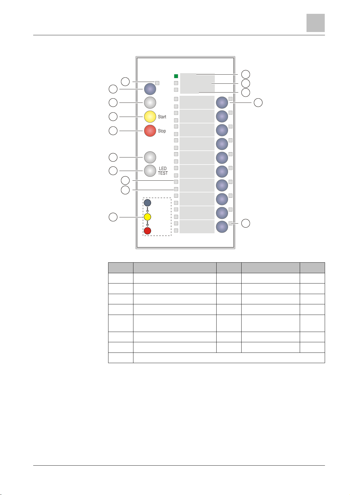
3.1.1 EVAC NL
Uitgeschakeld
Ontruimingsalarm
cbd
e
7
Selecteer
Zone 5
Zone 6
Zone 7
Zone 8
Zone 9
3
a
1
2
Totaal
Alarm
Zoemer
uit
3
4
Bedrijf
Storing
Zone 1
Zone 2
Zone 3
Zone 4
5
IN/UIT
6
g
f
i
Start
Stop 2x
Zone 10
Figure 2: ↑ PMI evacuation alarm
Button LED
1 Totaal alarm a Totaal alarm (red)
2 Zoemer uit b Bedrijf (green)
3 Start c Uitgeschakeld (yellow)
4 Stop d Storing (yellow)
5 IN/UIT e
EVAC zone
(yellow)
selection
6 LED TEST f Fault/Isolation (yellow)
7 Selecteer g Alarm (red)
i Information about using the keys
Building Technologies
21 |
Page 22

Setup of the Person Machine Interface
PMI
3
Building Technologies
A6V10211076_i_en_
--
Fire Safety
2015-12-15
3.1.1.1 Functions on the EVAC PMI
Button Function
1 Totaal alarm Pressing the button selects all EVAC zones
2 Zoemer uit Silences the buzzer of the EVAC PMI
3 Start Activates selected EVAC zones
4 Stop Deactivates selected EVAC zones
5 IN/UIT Switches selected EVAC zones on or off
6 LED TEST Activates the LED test on the EVAC PMI
7 Selecteer
LED Function
a Totaal alarm Indicates that 'Overall Alarm' has been activated
b Bedrijf Active as long as power supply is available
c Uitgeschakeld Active when at minimum one EVAC zone is switched off
d Storing ● Active when at least one fault is present in an EVAC zone
● Active (flashing) when the connection to the fire control panel is faulty
e
EVAC zone
selection
f Fault/Isolation Active when an EVAC zone has been switched off or a fault is present
g Alarm Active when all EVAC zones are activated
Active when the zone has been selected
Selects an EVAC zone for the issuing of
additional commands (Start, Stop, ON/OFF)
3.1.2 Key switch (optional)
You can use the key switch to release an access level. The accessible access
level is configurable.
The key switch has 2 positions:
● On (horizontal position)
● Off (vertical position)
3.1.3 Standard keys
22 | 184
See also
1 Logout timeout [➙ 118]
With the standard buttons, functions can be performed at the push of a button.
<Silence buzzer>
Switches the 'Station' buzzer off.
<Acknowledge>
● Acknowledges all events that can be acknowledged.
● Confirms presence (↑ 'AVC', 'IC')
● Switches the buzzer off
Page 23

Setup of the Person Machine Interface
Person Machine Interface with FBP [AU]
184
A6V10211076_i_en_
--
Fire Safety
2015-12-15
<Reset>
The two buttons a and b in the figure above are configurable standard buttons.
Fire brigade operation
Full operation
Resets all events that can be reset (password required).
<Alarm delay off>
● Switches off the alarm delay for all events.
● In the event of an alarm, the remote transmission or ↑ global alarming is
activated immediately.
<Premises manned>
● Switches between 'Manned operation' and 'Unmanned operation' operation
modes (password required).
● Opens the event list in case of a "mixed" condition (↑ visibility on several
'Areas' with different 'Manned operation' and 'Unmanned operation' settings).
<Alarm device>
Deactivates the ↑ alarm devices in the event of alarm (password required).
Configurable buttons
3
You can, for example, configure these two buttons with the following functions:
● 'Poll RT counter'
● 'Non-MCP zones OFF'
3.1.4 Other alarms
Pressing the 'More alarms' button opens the 'ALARMS' event list.
If the 'ALARMS' event list is already open, <More alarms> assumes the function of
the button <▼>, changing to the next alarm event upon activation.
3.2 Person Machine Interface with FBP [AU]
The operating unit [AU] includes the PMI [AU] with the 'Fire brigade panel' (FBP),
through which the fire detection installation can be operated. All important
information from the fire detection installation is indicated spontaneously on the
PMI or can be polled there.
Fire brigade operation is enabled with the key switch. The fire brigade has access
level 2,1. The <Silence buzzer>, <Silence Alarm>, <Reset>, <Disable>, and
<SEVERAL ALARMS> buttons can be operated by the fire brigade .
Full operation of all buttons from access level 2,2 can only be enabled with the
PIN.
Building Technologies
23 |
Page 24

Setup of the Person Machine Interfac
e
Person Machine Interface with FBP [AU]
3
Building Technologies
A6V10211076_i_en_
--
Fire Safety
2015-12-15
CONTROL FUNCTION
ACTIVATED/CONFIRM.
ALARM ROUTING
6127
345
8
2
FIRE BRIGADE PANEL
001 AAA
001 ABC
ABC
ZZZ ZZZ ZZZ
SEVERAL ALARMS
11
YYYY
910
SILENCE BUZZER
SILENCE A LARM
RESET
DISABLE
ACKNOWLEDGE
PREMISES MANNED
c
~
b
e
a
d
123
i
l
h
g
s
r
q
p
n
k
j
m
456
v
y
u
x
t
w
789
0#
*
C
f
o
z
ok
15
14
FC72x-xx
1
FIRE
FIRE PROTECTION
ACTIVATED
SMOKE CONTROL
ACTIVATED
WARNING SYSTEM
ACTIVATED
ALARM ROUTING
ACTIVATED
SYSTEM
POWER
FAULT
13
1 Alarm indicator ● Light up red in the event of an alarm
2 Display ● Event indication, e.g. type, place, status of event
● Menu, element and command indication
● Instructions may be displayed in the event of an alarm
WARNING SYSTEM
SILENCED
FAULT
ISOLATION
DETEC TOR TEST
CONTROL FUNCTION
ACTIVATED
FAULT/OFF
WARNING SYSTEM
ACTIVATED
FAULT/OFF
FIRE P ROTECTI ON
ACTIVATED
FAULT/OFF
SMOKE CONTROL
ACTIVATED
FAULT/OFF
ACTIVATED
FAULT/OFF
3 Navigation buttons
● For navigation in the display for, e.g., menu and command selection
and scrolling in lists
● Access level 2,2 required
4
Keypad with Menu key, ok key
and Cancel key
● Keypad for PIN entry (password), shortcut (menus), address entry
(element ID), parameter entry, entry of customer text
● The menu button opens the main menu
● The <ok> button can be used to run a selected command or open a
menu item. In windows with an entry field, the <ok> button moves the
cursor to the next entry.
● With the <C> cancel button, any operation sequence can be
canceled, and any open list or window can be closed.
● PIN entry required
5 Operating unit (AU) ● Pre-configured LEDs
● LEDs which can be configured according to specific customer
requirements
6 Key switch ● Enabling fire brigade operation with access level 2,1
7
<Silence buzzer>, <Silence
Alarm>, <Reset>, and
<Disable> standard buttons
Access level 2,1 required; fire brigade operation with key switch:
● <Silence buzzer> switches the buzzer off
● <Silence Alarm> deactivates alarm devices
● <Reset> resets all events that can be reset
● <Disable> stops the alarm in all 'Zones' which have issued an alarm
24 | 184
Page 25

Setup of the Person Machine Interface
Person Machine Interface with FBP [AU]
184
A6V10211076_i_en_
--
Fire Safety
2015-12-15
8
You can use inscription strips to inscribe the PMI. You will find a template for this
<Acknowledge> and
<Premises manned> standard
buttons
3
● <Acknowledge> acknowledges all events that can be acknowledged.
Confirms presence (AVC, IC).
● <Premises manned> switches between 'Manned' and 'Unmanned'
operation modes (PIN entry required). Opens the event list in the
case of a "mixed" condition (visibility on several areas with different
'Manned' and 'Unmanned' settings).
9 Softkeys 1–3
● Softkeys are buttons by means of which functions may be carried out
that are displayed in the three fields of the softkey line on the display.
● These three black fields contain the names of the functions in white
font.
● The functions of the softkeys may change depending on the situation
and the contents of the display.
● Always the most important functions are assigned to the softkeys 1
and 2.
● Access level 2,2 required.
10
Configurable buttons with
LEDs (can be configured
● Functions can be configured according to specific customer
requirements
independently)
11 <SEVERAL ALARMS> button ● Pressing <More alarms> opens the 'ALARMS' event list.
● If the 'ALARMS' event list is already open, <More alarms> assumes
the function of the button <▼>, changing to the next alarm event upon
activation.
● Access level 2,1 required; fire brigade operation with key switch
12 Configurable LEDs ● Freely configurable for the indication of events or conditions
13 System fault LED (yellow) ● Lights up yellow when a fault is present
14 Operation LED (green) ● Lights up green during operation
15
<Fire Protection Activated>,
● Light up red when activated
<Smoke Control Activated>,
<Warning System Activated>,
and <Alarm Routing Activated>
standard LEDs
Building Technologies
in document A6V10479789.
Different access levels for Australia as of MP6
The following access levels apply to FS720 fire detection systems for the
Australian market as of MP6:
Access levels as of MP6 Access levels <MP6
1 1
2 2.1
3.1 2.2
3.2 3
The access levels that apply as of MP6 work in exactly the same way as the
access levels for versions <MP6.
As stipulated by AS 4428.3, the operating elements within the 'Fire brigade panel'
are disabled in the event of a fire alarm if the operator has access level 2. The
introduction of access level 3.1 as of MP6 enables operating personnel who are
present during a fire to operate the 'Fire brigade panel' accordingly.
25 |
Page 26

Setup of the Person Machine Interface
Display
3
Building Technologies
A6V10211076_i_en_
--
Fire Safety
2015-12-15
Events occurring in the fire detection installatio
n are indicated on the display. A
ABCDEFGHI
1
2
3
3.3 Display
The display of the station has two displaying variants:
● Display without window
– Normal view
– Expanded ↑ visibility
– 'Fire Brig. view'
● Display with window for following representations
– Lists
– Input fields
– Command responses
3.3.1 Normal view
The display of a ↑ 'Station' in 'Standard view' has three sections.
001 AAA
001 ABC
ABC
YYYY 1
ZZZ
ABCDEFGHI
Figure 3: Display in normal view
ZZZ
ABCDEFGHI
ZZZ
Position Designation Function
1 Header ● Status indication and system time
● Information and titles for the working area
● Instructions for the operator
● Information for the operator
2 Working area ● Indication of lists
● Selection of list items
● Indication of windows
3 Softkey bar
● Display of the three functions that can be directly executed with the softkey
buttons
Identification of messages
special identification informs on the status of an event.
You will find details on the identification in the chapter 'Event status identification'.
26 | 184
See also
1 Event status identification [➙ 169]
Page 27

Setup of the Person Machine Interface
Display
184
A6V10211076_i_en_
--
Fire Safety
2015-12-15
3.3.2 Extended view
The display of events, elements, etc., comprises two lines in 'Standard view'.
The extended view shows a 4-line depiction of the selection. Additional information
such as e.g. additional customer texts can be displayed this way.
In the extended view there is a frame around four lines.
Figure 4: Display with extended view
With the <Switch to Extended view> and <Switch to Standard view> softkeys, you
can switch from 'Standard view' to 'Extended view' and vice versa.
Alternatively, the navigation buttons <►> and <◄> can be used to switch over.
3
3.3.3 Fire brigade view
For 'ALARM' events, the 'Fire Brigade message view' can be configured in the
Engineering tool.
An 'ALARM' event is displayed in double font size in the 'Fire Brigade message
view'.
Display with 'Fire Brig. view'
3.3.4 Display with window and list
The display with window and list is for the selection of a list item, which
corresponds to a submenu.
The figure below shows the display with an exemplary list:
Building Technologies
Figure 5: Example of the display with window and list
27 |
Page 28

Setup of the Person Machine In
terface
Display
3
Building Technologies
A6V10211076_i_en_
--
Fire Safety
2015-12-15
3.3.5 Display with window and input field
The display with window and input field has one or several input fields for entering
e.g. the PIN, an address or customer text.
The figure below shows the display with an exemplary window with input field:
Figure 6: Example of the display with window and input field
3.3.6 Display with window and command response
The display with window and command response is open after a command has
been entered. The operator therefore receives a confirmation for the command
entered.
Figure 7: Example of the display w ith window and command response
28 | 184
Page 29

Setup of the Person Machine Interface
Soft keys
184
A6V10211076_i_en_
--
Fire Safety
2015-12-15
3.4 Soft keys
When the user navigates through the topology, the softkey allocation does not
The figure below shows the part of the PMI including the softkeys.
Button for softkey function
Softkeys are buttons which you can use to carry out functions and which are
displayed in the three fields of the softkey line on the display. These three black
fields contain the names of the functions in white font.
The functions of the softkeys change dynamically depending on the situation and
the contents of the display.
Always the most important functions are assigned to the softkeys 1 and 2.
3
change depending on the context; the assignment remains fixed. If a softkey
function cannot be executed at a point in the topology, the inscription in the field is
hidden.
The table below lists an exemplary softkey assignment.
Softkey / Option Function
'Show intervention text'1 Shows the intervention text of the selected event.
'Jump back'
Displays the list the selected event has been taken from. Back from the view
Intervention text or Details.
'Execute command' Opens the 'Select command' window.
'More options' Opens the 'Select option' window.
'Show details'
2
Shows details of the selected event or element.
'Lower level' Changes to the next lower hierarchy level.
'Upper level' Changes to the next higher hierarchy level.
'Jump to begin' / 'Jump to
Within a list, jumps to the top or end of the list
end'
'Show topology '
3
Jumps to the selected element in the topology.
'Show active detectors' Shows a list of all active detectors, corresponding to an event list.
1
Softkey / Option is only displayed when intervention text is available at this point
2
Softkey / Option only available in 'Access level 3'
3
Softkey / Option only available as of 'Access level 2.1'
See also
1 Normal view [➙ 26]
Building Technologies
29 |
Page 30

Setup of the Person Machine Interface
Navigation buttons
3
Building Technologies
A6V10211076_i_en_
--
Fire Safety
2015-12-15
3.5 Navigation buttons
The following figure shows the navigation buttons in the ↑PMI:
Figure 8: Navigation buttons
● The navigation buttons work in the same way as the arrow keys on a PC
keyboard.
● The next entry in a list can be highlighted with the buttons <▲> and <▼>.
● It is possible to change to a higher or lower hierarchy level with the buttons <◄>
and <►>.
● In a command list, the highlighted command can be executed with the button
<►>.
● When characters are entered, the character to the left of the cursor position is
deleted by pressing the button <▲>.
3.6 Keypad
The following figure shows the keyboard and <MENU>, <ok> and <C> (Cancel)
buttons:
2
1
1 Keypad 3 <ok>
2 <MENU> 4 <C> (Cancel button)
The key panel serves for numeric and alphanumeric entries.
34
30 | 184
Page 31

Setup of the Person Machine Interface
LEDs
184
A6V10211076_i_en_
--
Fire Safety
2015-12-15
Numeric entry
C
Numeric entry is applicable in the following cases:
● PIN entry (password)
● Shortcuts (Menus)
● Address entry (Element ID)
● Parameter entry
Alphanumeric entry
The alphanumerical input is for entering customer text.
3.6.1 Menu button
= <MENU> button
● The <MENU> button opens the main menu.
● The PIN entry dialog is displayed if no 'Access level' is enabled.
● Opening the main menu is independent from the current display contents.
3.6.2 Button 'ok'
3
ok
= <ok>, < > = button
With <ok> a selected entry or menu item can be executed or opened.
In windows with an entry field, the <ok> button moves the cursor to the next entry.
3.6.3 Button 'C'
= Cancel button <C>
With <C>, any operation sequence can be cancelled and any open list or window
can be closed.
3.7 LEDs
The LEDs on the ↑Person Machine Interface signal 'Events' and conditions. In
addition, the LEDs support the operator's orientation. The LEDs can light up in red,
yellow, or green. The LEDs can be configured according to customer-specific
requirements.
The LED colors can, for example, signal the following information:
Red ● ALARM
Yellow ● Fault
● Activations, e.g., remote transmission,↑ alarm devices,
control function
● Isolation
● Deactivation, e.g. remote transmission, alarm devices,
control function
Building Technologies
Green ● System is in operation
Additional information on the conditions of the LEDs (steady on, steady off or
flashing) can be found in the relevant chapter.
31 |
Page 32

Setup of the Person Machine Interface
Menu structure
3
Building Technologies
A6V10211076_i_en_
--
Fire Safety
2015-12-15
3.8 Menu structure
MAIN MENU Menu items / Functions Selection / window See page
'Message summary' 'Message summary' Message category Link [➙ 170]
'Functions' 'On / Off' 'Select element category' Link [➙ 45]
'Test' 'Select element category'
'Activate / Deactivate' 'Select element category' Link [➙ 78]
'Information' 'Select element category' Link [➙ 89]
'Configuration' 'Select element category' Link [➙ 92]
'Maintenance' 'Select element category' Link [➙ 175]
'Reports' Station / Module Link [➙ 91]
'All functions' 'Select element category' Link [➙ 62]
'Favorites'
1
e.g. 'Function On/off' 'Select element category' Link [➙ 36]
e.g. 'All functions' 'Select element category' Link [➙ 36]
e.g. 'LED test' LED test Link [➙ 36]
'Topology' ↑ 'Detection tree' 'Area' Link [➙ 69]
'Hardware tree' ↑Station / module Link [➙ 69]
↑ 'Control tree' 'Alarming control group'
'Element search' 'Start with category'
/ e.g. 'Evac ct'
/ e.g. 'ALARM'
/ e.g. 'Fire ct'
1
1
1
'Select element category' /
Link [➙ 69]
Link [➙ 71]
Enter address
'Start with address' Enter address Link [➙ 71]
'Event memory' 'Select station' Events Link [➙ 169]
'Login/logout' Input dialog Link [➙ 58]
'Settings/administration' 'Change language' 'Change language' Link [➙ 103]
'Manage PINs' 'Change PIN'
Link [➙ 104]
'Create PIN'
'Delete PIN'
'LED test' 'LED test' Link [➙ 77]
'Set buzzer volume' 'Set buzzer volume' Link [➙ 105]
'Display settings' 'Display brightness'
Link [➙ 106]
'Display contrast'
32 | 184
'System commands' 'Set system time'
'Activate exp. visibility'
'Deactivate exp.visibility'
'Show licence texts' License text is displayed
1
Configurable
See also
1 Settings / Administration [➙ 103]
1 Testing [➙ 74]
Link [➙ 106]
Link [➙ 61]
Page 33

Setup of the Person
Machine Interface
Cerberus Remote
184
A6V10211076_i_en_
--
Fire Safety
2015-12-15
3.9 Cerberus Remote
You will find more information about license keys in document
A6V10210362
.
The connection to a
↑'Station
' with a l
icense key is also possible via a '
Station
'
Cerberus
-
Remote
has the same
↑
visibility as the connected '
Station
'. You can
The connection with a '
Station
' is shown by the
↑
Person Machine Interface
Cerberus-Remote is software for the PC which can be used to display the
↑ Person Machine Interface of a ↑ 'Station' on the PC. For example, it can be used
to access the ↑ site for maintenance purposes.
Depending on the operation mode, Cerberus-Remote can either be used for
display purposes or for display and operation purposes.
The link between Cerberus-Remote and a 'Station' can be structured as follows:
● Local connection via any 'Station' in the system
● Connection via the Global Access Point (GAP)
Cerberus-Remote is an integrated part of Cerberus-Engineering-Tool, but can also
be installed on a PC as the standalone application 'FX7220'.
You will need an installed ↑ license key and appropriate authorization for the
'Station' in order to use Cerberus-Remote. The license key must support the
Cerberus-Remote function. The license key need only be installed in the 'Station'
that has the Person Machine Interface that is to be displayed in Cerberus-Remote.
See chapter 'Applicable documents'.
3
without a license key.
therefore gain global visibility with Cerberus-Remote in a networked ↑ site. To do
so, the license key must be installed in a ↑ 'Station' with global visibility and
connected to Cerberus-Remote.
(display, LEDs, keys) transmitted.
The 'Cerberus-Remote access' operation mode is indicated by a red frame
around the Person Machine Interface.
An enable granted for Cerberus-Remote is retained when a 'Station' restarted.
See also
1 Cerberus Remote operation modes [➙ 38]
1 Enabling / Disabling Cerberus Remote [➙ 96]
1 Operating Cerberus Remote [➙ 99]
Building Technologies
33 |
Page 34

Setup of the Person Machine Interface
Cerberus Mobile
3
Building Technologies
A6V10211076_i_en_
--
Fire Safety
2015-12-15
You will find more information about '
Cerberus Mobile
' in document
You will find more information about
↑
license keys in document
A6V10210362
.
3.10 Cerberus Mobile
'Cerberus Mobile' is an app for smartphones. Depending on the operation mode,
Cerberus Mobile can be used either to display or to display and operate the
↑ 'Station'. For example it can be used to access the fire detection system for
maintenance purposes.
A6V10418718. See chapter 'Applicable documents'.
You will need an installed ↑ license key and appropriate authorization for the
↑ 'Station' in order to use Cerberus Mobile. The license key must support the
'Cerberus Mobile' function.
See chapter 'Applicable documents'.
34 | 184
Page 35

Operation functions
Selection and opening / execution
184
A6V10211076_i_en_
-
-
Fire Safety
2015-12-15
4 Operation functions
The following chapters contain descriptions of important functions for directly
operating the ↑ site.
You will find information on the system functions in the corresponding chapter.
See also
1 System functions [➙ 111]
4.1 Selection and opening / execution
After calling up the main menu and any other list, the first entry in the list is
selected. The selection is indicated by a rectangular frame around the entry.
The opening of a list item or the execution of a list command is performed by
moving the cursor to the selected entry and pressing <ok>.
Other methods to open or execute a highlighted list entry are given by pressing the
following buttons:
● <►>
● <Number> on the numerical block (given number in brackets – only in selection
lists)
4
Changing the selection
The selection indicated is changed as follows:
Button Consequence
<▼> Next entry
<▲> Previous entry
<More alarms>
<Number> + <ok>
More Options' + 'Jump to begin' softkeys Jump to the top of the list
More Options' + 'Jump to end' softkeys Jump to the end of the list
4.2 Scrolling
You can use the navigation keys to scroll through a displayed list in the display.
You can scroll to the start/end of the lists (limited function) and back in the
following lists:
● Option lists
● Command lists
● Element category lists
In all other lists, you can scroll beyond the end of the list to the start of the list and
back.
Opens alarm list / jumps to the next
entry in the alarm list shown
Goes to the entry with the number
entered – not in selection lists
See also
1 List representation and list types [➙ 171]
Building Technologies
35 |
Page 36

Operation functions
Indication of the position and length of the list
4
Building Technologies
A6V10211076_i_en_
--
Fire Safety
2015-12-15
4.3 Indication of the position and length of the list
There is a vertical bar along the side of a list when the list is longer than can be
indicated on the display.
The black part of the bar shows the position and size of the part of the list you can
see in relation to the entire list.
Examples for the representation in different lists:
1 Bar in normal view with list 2 Bar in window with list
4.4 Shortcut
A shortcut serves for the direct execution of an entry in a selection list by pressing
a numeric key.
In a command list, for example, you can execute a command directly by entering
the corresponding number.
The numbers for the shortcut are shown in the list entry line, on the right and in
brackets.
4.5 Favorites
You can use favorites to execute several operation sequences or one operating
sequence in an operation sequence.
A maximum of 8 favorites are configured and you can select them from the favorite
list in the 'Favorites' main menu item.
See also
1 Event status identification [➙ 169]
36 | 184
Page 37

Operation functions
Entry of
numbers and letters
184
A6V10211076_i_en_
-
-
Fire Safety
2015-12-15
4.6 Entry of numbers and letters
In input fields with more than one line, you cannot change back to a line above
You can use the keyboard to enter numbers and letters in input dialogs.
Numeric entry
● The number of underscores corresponds to the number of possible positions
for the entry.
● The overwrite mode is set by default; there is no insert mode.
● Horizontal navigation within the input field is possible with the keys <◄> and
<►>.
● Use <▲> to delete the character to the left of the cursor position.
● Use <ok> to save the entered value and exit the input field.
– When there are several input fields in the window, the cursor jumps to the
next field by pressing <ok>.
– If the cursor position is in the last or only input field, close the input dialog
by pressing <ok>.
● Use <C> to cancel the input and close the dialog without saving.
Alphanumeric entry
● Alphanumeric entries are only possible in particular input fields, e.g. for
customer text.
● Letters are entered in the same way as letters on telephones. You can select
the corresponding letter by pressing a key several times.
● Switching between lower and upper case letters is possible with the key <*>
and only applies for the next character.
4
the cursor position.
Building Technologies
37 |
Page 38

Operation functions
Cerberus Remote operation modes
4
Building Technologies
A6V10211076_i_en_
--
Fire Safety
2015-12-15
You will find more information about license keys in document
A6V10210362
.
As operation on a
↑'Station
' must have priority, this restriction (blocking) on the
The LED test also tests the display. However, the LEDs are not displayed in
You can configure a permanent authorization for
Cerberus
-
Remote
in
Cerberus
-
4.7 Cerberus Remote operation modes
Cerberus-Remote has the following operation modes:
● 'Limited access (view only)'
● 'Full access (view/operation)'
For both operation modes, an authorization must be configured on the ↑ 'Station'.
In addition, a ↑ license key must be installed. The license key must support the
Cerberus-Remote function.
See chapter 'Applicable documents'.
'Limited access (view only)'
In this operation mode, Cerberus-Remote indicates the same as the ↑ 'Station'
connected to it, but you cannot operate the linked 'Station'.
The figure in Cerberus-Remote indicates the display with all indicated texts, all
LEDs in their current state and all buttons.
'Full access (view/operation)'
In this operation mode, the connected 'Station' is visualized as in the 'Limited
access (view only)' operation mode. Additionally, the 'Station' can be operated with
Cerberus-Remote, while normal operation on the 'Station' is blocked, but can be
reactivated.
'Station' can be canceled at any time.
Each time an attempt is made to operate the ↑ 'Station', a window is displayed
with the option to abort the connection with Cerberus-Remote.
'Cerberus-Remote'.
Engineering-Tool. You will find more information about this in document
A6V10210424.
See also
1 Enabling / Disabling Cerberus Remote [➙ 96]
38 | 184
Page 39

Operation functions
Cerberus Mobile operation modes
184
A6V10211076_i_en_
-
-
Fire Safety
2015-12-15
4.8 Cerberus Mobile operation modes
Two operation modes can be specified for 'Cerberus Mobile' at the ↑ 'Station':
● 'Limited access (view only)'
● 'Full access (view/operation)'
The operation mode must be configured at the 'Station'.
'Limited access (view only)'
In this operation mode, 'Cerberus Mobile' displays ↑ 'Station' events. The events
displayed are determined by the configured 'Visibility' for 'Cerberus Mobile'. In this
operation mode, you cannot operate the 'Station' with 'Cerberus Mobile'.
'Full access (view/operation)'
In this operation mode, you can operate the ↑ 'Station' with the controls in
'Cerberus Mobile'. The events displayed are determined by the configured
'Visibility' for 'Cerberus Mobile'.
4
Building Technologies
39 |
Page 40

Operation
ALARM Procedure
5
Building Technologies
A6V10211076_i_en_
--
Fire Safety
2015-12-15
Certain commands on the fire con
trol panel can only be executed by the service
System without delayed alarm transmission (AVC)
5 Operation
In this part of the document you will find brief descriptions and detailed operation
sequences for important functions of the fire detection installation. In addition, you
can find your preferred procedures in the representation of exemplary operation
sequences.
technician or someone with access level 3. You will find a description of these
specific commands in document A6V10210416. See chapter 'Applicable
documents'.
5.1 ALARM Procedure
If your fire detection system has no delayed alarm transmission function ('AVC),
the variant 'Fire Brigade in' 'mm:ss' in Step 2 (see below) does not apply.
1 <Acknowledge> 5 <Alarm device>
2 Top line on the display A <Alarm delay off>
3 <Softkey 2> 'Show intervention text' if displayed R <Reset>
4 Indication of the fire location on the display
40 | 184
Page 41

Operation
ALARM Procedure
184
A6V10211076_i_en_
--
Fire Safety
2015-12-15
Procedure in the event of alarm
Reset
Step Action / Condition Consequence / Status
5
1
Press <Acknowledge> on the ↑ Person
Machine Interface
2 Read top line on display
● 'Fire Brigade requested' ⇨ 'ALARM' is transmitted to the fire brigade
● 'Fire Brigade in' 'mm:ss' ⇨ 'ALARM' is transmitted to fire brigade in mm:ss
● 'Call Fire Brigade !' if:
– Remote transmission switched off
– Remote transmission blocked or
defective
– No remote transmission available
3
Press 'Show intervention text' <softkey 2> ' if
displayed
or press <Show intervention text> button
Press <Jump back>
4 Read off fire location on display
5
Optional: Press <Alarm device> on the
Person Machine Interface (password
required)
6 Go to the fire location
⇨ With 'AVC', countdown t2 for examining the cause
of 'ALARM' starts
Remaining time is shown as Countdown
⇨ Fire brigade must be called by phone!
⇨ No automatic transmission to fire brigade
⇨ Intervention text is displayed
⇨ Fire location is displayed
⇨ Deactivates the acoustic ↑ alarm devices
7
Decide: MAJOR INCIDENT or ↑ minor
incident
Procedure in the event of a major incident or minor incident
Condition MAJOR INCIDENT ↑ Minor incident
Fire brigade has been called Save people
Guide the fire brigade to the fire
location
Fight the fire
'Fire Brigade in' 'mm:ss'
Countdown is running
Trigger the manual call point
immediately
or
Press <Alarm delay off>
'Call Fire Brigade !'
Call the fire brigade on the phone! Press <Reset> (password required)
No automatic transmission to
the fire brigade
A password is required for resetting.
It may be necessary to air the room before 'Reset' is possible.
You can temporarily ↑ switch off elements that cannot be reset.
Try to prevent fire brigade
deployment
Press <Reset> (password required)
Building Technologies
41 |
Page 42

Operation
ALARM procedure PMI with FBP [AU]
5
Building Technologies
A6V10211076_i_en_
--
Fire Safety
2015-12-15
System without delayed alarm transmission (AVC)
CONTROL FUNCTION
ACTIVATED/CONFIRM.
ALARM ROUTING
1
5
5.2 ALARM procedure PMI with FBP [AU]
If your fire detection system has no delayed alarm transmission function ('AVC'),
the variant 'Fire Brigade in mm:ss' in Step 2 (see below) does not apply.
Prerequisite
● You must have access to the PMI with FBP.
● You must have the PIN for the 2,1 access level.
FIRE BRIGADE PANEL
FC72x-xx
FIRE
FIRE PROTECTION
ACTIVATED
SMOKE CONTROL
ACTIVATED
WARNING SYSTEM
ACTIVATED
ALARM ROUTING
ACTIVATED
SYSTEM
POWER
FAU LT
1 <Acknowledge> 4
001 AAA
001 ABC
ABC
2
4
ZZZ ZZZ ZZZ
3
SEVERAL AL ARMS
YYYY
SILENCE BUZZER
SILENCE ALARM
RES ET
DISABLE
ACKNOWLEDGE
PREMISES MANNED
c
f
b
~
i
h
g
s
r
q
p
e
a
d
123
456
789
*
o
l
n
k
j
m
v
y
x
u
t
w
0#
C
z
ok
Indication of the fire location on the
display
2 Top line on the display 5 <Silence Alarm>
3 <Softkey 2> 'Show intervention text' if displayed
WARNING SYST EM
SILENCED
FAULT
ISOLATION
DETECTOR TE ST
CONTROL FUNCTION
ACTIVATED
FAULT/OFF
WARNING SYST EM
ACTIVATED
FAULT/OFF
FIRE P ROTECTI ON
ACTIVATED
FAULT/OFF
SMOKE CONTROL
ACTIVATED
FAULT/OFF
ACTIVATED
FAULT/OFF
42 | 184
Page 43

Operation
ALARM procedure PMI with FBP [AU]
184
A6V10211076_i_en_
--
Fire Safety
2015-12-15
Procedure in the event of alarm
Reset
Step Action / Condition Consequence / Status
5
1
Press <Acknowledge> on the Person
Machine Interface
2 Read top line on display
● 'Fire Brigade requested' ⇨ 'ALARM' is transmitted to the fire brigade
● 'Fire Brigade in' 'mm:ss' ⇨ 'ALARM' is transmitted to fire brigade in mm:ss
● 'Call Fire Brigade !' if:
– Remote transmission switched off
– Remote transmission blocked or
defective
– No remote transmission available
3 Only with PIN for the 2,2 access level:
Press <Softkey 2> 'Show intervention text'
or press <Show intervention text> button
Press <Jump back>
4 Read off fire location on display
5 If alarm devices are activated:
Press <Silence Alarm> on the Person
Machine Interface
6 Go to the fire location
⇨ With 'AVC, countdown t2 for examining the cause
of 'ALARM' starts
Remaining time is shown as Countdown
⇨ Fire brigade must be called by phone!
⇨ No automatic transmission to fire brigade
⇨ Intervention text is displayed
⇨ Fire location is displayed
⇨ Deactivates the acoustic alarm devices
7
Decide: MAJOR INCIDENT or ↑ minor
incident
Procedure in the event of a major incident or minor incident
Condition MAJOR INCIDENT Minor incident
Fire brigade has been called Save people
Guide the fire brigade to the fire
location
Fight the fire
'Fire Brigade in' 'mm:ss'
Countdown is running
Trigger the manual call point
immediately
or
Press <Alarm delay off>
'Call Fire Brigade !'
Call the fire brigade on the phone! Press <Reset>
No automatic transmission to
the fire brigade
1
Before resetting, the acoustic alarm devices must be deactivated. See Step 5.
Try to prevent fire brigade
deployment
Press <Reset>
1
1
Building Technologies
It may be necessary to air the room before 'Reset' is possible.
You can temporarily ↑ switch off elements that cannot be reset.
43 |
Page 44

Operation
Procedure in case of Fault
5
Building Technologies
A6V10211076_i_en_
--
Fire Safety
2015-12-15
A list of possible '
Faults
' and how they are eliminated can be found in the chapter
5.3 Procedure in case of Fault
Step Action
1 Press <Silence buzzer> on the ↑ Person Machine Interface
2 Read message/fault location on the display
3 Go to the fault location
4 Eliminate the cause of the fault
'Faults / Troubleshooting'. If you cannot eliminate 'Fault', please contact your
service provider.
'Fault' and 'Intervention Concept' (IC)
On consideration of 'Intervention Concept', events of the 'Fault' category can be
assigned their own sequence. This sequence may be configured differently and
depends on the ↑ 'Manned operation' / ↑ 'Unmanned operation' operation mode.
An exemplary process following 'Fault', taking into account 'Intervention Concept',
is graphically shown in chapter 'Intervention Concept (IC) and is outlined below:
'Fault' has occurred
● The remote transmission for 'Faults' is activated in 'Unmanned operation'
operation mode.
● The remote transmission for 'Manned operation' is activated in 'Faults'
operation mode unless 'Fault' is acknowledged within the delay t1.
Acknowledging 'Fault'
1. Press <Acknowledge> before the expiry of t1.
2. Read the 'Fault'location on the display.
3. Go to the 'Fault' location.
4. Rectify 'Fault'.
See also
1 Intervention concept (IC) [➙ 163]
1 Faults / Troubleshooting [➙ 174]
44 | 184
Page 45

Operation
Switching off / Switching on
184
A6V10211076_i_en_
--
Fire Safety
2015-12-15
5.4 Switching off / Switching on
System parts that have been switched off make it impossible to acquire and
●
You must switch deactivated parts of the '
Site
' bac
k on as soon as possible.
If a deac
tivated '
Zone
' is the only '
Zone
' in a
↑'Section
', the '
Section
' is also
If a deactivated '
Zone
' is the only '
Zone
' in a
↑'Section
', the '
Section
' is also
You will find information on temporarily
↑
switching off detector zones in chapter
The fastest method for switching off or on is to enter a known address in the
WARNING
process alarms or faults!
Fire may spread unhindered.
● Deploy staff to monitor the deactivated area.
To avoid ↑ false alarms or fault messages, you can switch off parts of a ↑ 'Site'
↑ in certain situations, e.g., for the purpose of maintenance work.
When a part of a system is switched off, the 'Isolation' LED is on.
The situations in which part of a 'Site' should be switched off, depends on the
detectors used as well as on possible deceptive phenomena such as smoke, dust,
heat or vapour.
indicated as deactivated.
5
Examples of switching off/on are provided in the following chapters.
5.4.1 Switching a detector zone off / on
indicated as deactivated.
'Temporary switching-off [➙ 51]'.
In which situations a detector zone should be switched off, depends on the
detectors used as well as on possible deceptive phenomena such as smoke, dust,
heat or vapour.
'Enter address' window.
In the configuration, a standard button can be given the function of directly
opening the menu with the 'Enter address' input dialog to select a detector zone.
In the following exemplary operating sequence the process is shown without a
known address.
Building Technologies
45 |
Page 46

Operation
Switching off / Switching on
5
Building Technologies
A6V10211076_i_en_
--
Fire Safety
2015-12-15
↑ Switching off a detector zone
1. Select 'Main menu' > 'Functions'.
The 'Functions' window is open.
2. Select 'On / Off'.
A list of all element categories on which a command of the 'On / Off'
command group can be executed is indicated.
3. Select the 'Element category' 'Zone'.
The 'Enter address' window is open.
4. Press <ok> without entering an address.
All 'Zones' are displayed.
5. Select a 'Zone' and press <'Execute Commands>.
The 'Select command' window is open.
6. WARNING! System parts that have been switched off make it impossible to
acquire and process alarms or faults! Select the 'OFF' command and confirm
with <ok>.
The window with the command response confirms the selected command.
'Zone' is switched off.
Exemplary representation of the aforementioned operation sequence for
↑ switching off a detector zone:
Functions
Access level 2.1
Exit with <C>
On / Off
Test
Activate / Deactivate
Information
(1)
(2)
(3)
(4)
Configuration
Maintenance
Reports
All functions
Message summary Event memory LED
test
κ Select 'On / Off', continue with <ok>
Selecting element category
Zone
Area
Section
Sounder
↑ Fire control group
(1)
(2)
(3)
(4)
(5)
(5)
(6)
(7)
(8)
46 | 184
κ Select 'Zone', continue with <ok>
Page 47

Operation
Switching off / Switching on
184
A6V10211076_i_en_
--
Fire Safety
2015-12-15
Enter address
Zone ---------
Confirm with <ok>/Exit with <C>
Delete with <Cursor up>
κ Continue with <ok> without entering an address
021 Zones
5
Zone
Zone
Zone
Zone
Execute
Commands
κ Select 'Zone', continue with <Execute Commands>
10
11
12
13
Power supply room
EDP room, false floor
EDP room
Office 21
Show
Topology
Select command
OFF
OFF/timer
κ WARNING! System parts that have been switched off make it impossible to
(2)
(4)
acquire and process alarms or faults! Select 'OFF', continue with <ok>
Command response
Execute command
OFF
Building Technologies
Command executed
Switching a detector zone on
Proceed as with ↑ switching off, but select the 'ON' command.
Alternatively, with 'Message summary' from the main menu and 'Event category'
'Isolations', you can also select the corresponding 'Zone' and reactivate with the
<softkey> 'Execute Commands'.
See also
1 Execute commands – object-oriented [➙ 64]
47 |
Page 48

Operation
Switching off / Switching on
5
Building Technologies
A6V10211076_i_en_
--
Fire Safety
2015-12-15
If a deactivated '
Detector
' is the only '
Detector
' in a '
Zone
' or if all '
Detectors
' in a
You will find information on temporarily
↑
switching off detectors in chapter
5.4.2 Switching a detector off / on
'Zone' are deactivated, the 'Zone' is indicated as deactivated.
'Temporary switching-off [➙ 51]'.
↑ Switching off the 'Detector'
1. Select 'Main menu' > 'Topology'.
The 'Topology' window is open.
2. Select 'Detection tree' and click <ok>.
The elements of 'Detection tree' are displayed.
3. Select the element 'Area 1'.
The elements of 'Area 1' are displayed.
4. Select 'Area 1' and press 'Lower level' <softkey 2>.
All 'Sections' in 'Area 1' are displayed.
5. Select 'Section 1' and press 'Lower level' <softkey 2>.
All 'Zones' in 'Section 1' are displayed.
6. Select 'Zone 1' and press 'Lower level' <softkey 2>.
All detectors of 'Zone 1' are displayed.
7. Select 'Detect. 1' and press 'More Options' <softkey 3>.
The 'Select option' window is open.
8. Select 'Execute commands'.
The 'Select command' window is displayed.
9. WARNING! System parts that have been switched off make it impossible to
acquire and process alarms or faults! Select 'OFF'.
The command is executed.
The window with the command response is open.
The detector is switched off.
Exemplary representation of the aforementioned operation sequence for
↑ switching off a detector:
Topology
Access level 2.1
Exit with <C>
48 | 184
↑ Detection tree
Hardware tree
↑ Control tree
Function
On/Off
κ Select 'Detection tree', continue with <ok>
(1)
(2)
(3)
Function
All
LED
test
Page 49

Oper
ation
Switching off / Switching on
5
184
A6V10211076_i_en_
--
Fire Safety
2015-12-15
001 Element Detection tree
Area 1 Portaphone AG
Lower
level
κ Select 'Area 1', continue with 'Lower level' <Softkey 2>
005 Elements
Portaphone AG
Section
Section
Section
Section
Upper
κ Select 'Section 1', continue with 'Lower level' <Softkey 2>
level
1
2
3
4
Ground floor
1st floor
1st floor / EDP room
2nd floor
Lower
level
005 Elements
Ground floor
Zone
Zone
Zone
Zone
1
2
3
4
Reception hall
Corridor
Warehouse
Reception hall
Execute
Commands
Area 1
Execute
Commands
Section 1
Upper
level
κ Select element 'Zone 1', continue with 'Lower level' <softkey 2>
Lower
level
Commands
002 Elements
Reception hall
Detect.
Detect.
1
2
Main entrance
Reception
Upper
level
κ Select 'Detect. 2', continue with 'More Options' <softkey 3>
Execute
Zone 1
More
Options
Building Technologies
49 |
Page 50

Operation
Switching off / Switching on
5
Building Technologies
A6V10211076_i_en_
--
Fire Safety
2015-12-15
As an alternative, you can select the corresponding detector or '
Zone
' via the
Selecting option
Execute commands
Jump to link
Show details
κ Select 'Execute commands' option, continue with <ok>
(3)
(4)
(5)
Select command
OFF
Activate alarm indicator
Deactivate alarm indicator
κ WARNING! System parts that have been switched off make it impossible to
(1)
(3)
(4)
acquire and process alarms or faults! Select 'OFF' command
Command response
Execute command
OFF
Command executed
Switching on the 'Detector'
Proceed in the same way as when ↑ switching off 'Detector', but select the 'ON'
command as shown below.
Select command
ON (2)
κ Select 'ON' command
'Message summary' main menu item and the 'Isolations' message category and
switch it back on with the 'More Options', 'Execute commands', and 'ON' softkey.
50 | 184
Page 51

Operation
Switching off / Switching on
184
A6V10211076_i_en_
--
Fire Safety
2015-12-15
5.4.3 Temporary switching-off
Temporary switching
-
off is only possible at
level
'
Area
','
Section
', '
Zone
', or
If a detector has been temporarily isolated and its '
Zone
' has been permanently
If a detector has been temporarily isolated and its '
Zone
' has been temporarily
If all detectors in a '
Zone
' ha
ve been isolated and the time limit for the isolation of
'Detector'.
Override for different settings
isolated, the detector is also permanently isolated.
isolated, the time limit for the isolation of the 'Zone' also applies for the detector.
a detector elapses, the 'Zone' is displayed as switched on.
5
The 'Temporary ↑ switching-off' function can be used to set a time limit for
'Isolation'. The isolated part of the ↑ 'Site' is switched back on automatically after
the time period entered.
The figures below show exemplary operation sequences to temporarily ↑ switch off
'Section':
1. Select 'Main menu' > 'Element search'.
2. Select 'Start with category'.
Selecting element category
Zone
Area
↑ Section
Detector
RT control
κ Select 'Section' and confirm with <ok>.
(1)
(2)
(3)
(4)
(5)
Enter address
↑ Section 1-------Confirm with <ok>/Exit with <C>
Delete with <Cursor up>
κ Enter the address: e.g., 1. Confirm with <ok>.
Building Technologies
51 |
Page 52

Operation
Switching off / Switching on
5
Building Technologies
A6V10211076_i_en_
--
Fire Safety
2015-12-15
The adjustable duration may be limited, depending on the country.
Select command
All zones ON
All zones OFF/timer
MCP zones OFF
Non-MCP zones ON
Non-MCP zones OFF
κ WARNING! System parts that have been switched off make it impossible to
(2)
(3)
(4)
(5)
(6)
acquire and process alarms or faults! Select 'All zones OFF/timer' and confirm
with <ok>.
Enter duration
05:00
(hh:mm)
Confirm with <ok>/Exit with <C>
Delete with <Cursor up>
κ Enter the duration: e.g., 5 hours.
You receive a command response.
Execute command
All zones OFF/timer
Command executed
The duration of the 'Isolation' may be changed subsequently.
An unlimited 'Isolation' can be temporarily limited, and vice versa.
52 | 184
Page 53

Operation
Switching off / Switching on
184
A6V10211076_i_en_
--
Fire Safety
2015-12-15
5.4.3.1 Polling the isolation time
The expiry reminder must be configured i
n '
Cerberus
-
Engineering
-
Tool
' > task
You will find more information about configuring the expiry reminder in document
When the remote transmission Fire has been switched off, the fire brigade cannot
●You must switch the '
RT Fire
' back on as soon as possible.
The '
RT Fire
' is normally switched on and may only be switched off in particular
If a 'Zone' or 'Detector' level is temporarily switched off, you can poll the remaining
switching-off time at the ↑ 'Station'.
1. Select 'Main menu' > 'Message summary' > 'Isolations'.
2. Select the isolated element for which you wish to poll the remaining isolation
time.
3. Select 'Execute commands'.
The 'Select command' window is displayed.
4. Select 'Show remaining off time' and confirm with <ok>.
The remaining switching-off time is shown.
Execute command
Show remaining off time
Element is switched off
until 2013-11-16 13:49:49
5
5.4.3.2 Expiry reminder for temporary switching-off
An expiry reminder is displayed prior to the expiry of temporary isolation. You can
configure how long before a temporary isolation the reminder is displayed in
'Cerberus-Engineering-Tool'.
card 'Operation' > 'Global system configuration' > 'Global behaviour' > 'Details'
tab.
'A6V10210424'. See chapter 'Applicable documents'.
5.4.4 Switching off / on the remote transmission Fire
WARNING
be called up in the event of fire!
Fire may spread unhindered.
● Deploy staff to monitor the 'Site'.
cases, e.g. for a function check of controls.
Building Technologies
53 |
Page 54

Operation
Switching off / Switching on
5
Building Technologies
A6V10211076_i_en_
--
Fire Safety
2015-12-15
↑ Switching off ↑ 'RT Fire'
1. Select 'Main menu' > 'Topology'.
The three partial topology trees are listed.
2. Select ↑ 'Control tree'.
The 'Select element category' window is open.
3. Select the 'Alarmg.' list item.
The 'Elements' window is open.
4. Select 'Alarmg. 2' and press 'Execute Commands' <softkey 2>.
The 'Select command' window is open.
5. WARNING! When the remote transmission Fire has been switched off, the
fire brigade cannot be called up in the event of fire! Select the 'RT FIRE
channels OFF' command and press <ok>.
The command response confirms that the command has been executed.
The 'RT Fire' is switched off.
The LED 'Remote alarm Off' on the ↑ Person Machine Interface is illuminated.
LED statuses:
● Off
● Steady on with isolation
● Flashing with fault
Example of ↑ switching off 'RT Fire' using 'Topology' main menu
item:
Topology
Exit with <C>
↑ Detection tree
Hardware tree
↑ Control tree
Function
On/Off
κ Select 'Control tree', continue with <ok>
(1)
(2)
(3)
Function
All
003 Elements Control tree
Evac gr
Alarmg.
Fire gr
2
2
3
Evac control groups
Standard alarming controls
Elevator control
Access level 2.1
LED
test
54 | 184
κ Select 'Alarmg.', continue with <ok>
Lower
level
Execute
Commands
Page 55

Op
eration
Switching off / Switching on
5
184
A6V10211076_i_en_
--
Fire Safety
2015-12-15
004 Elements
Standard alarming controls
IntS.Ct
RT fire
ExtS.Ct
RTfault
1
1
2
2
Internal sounder
Remote transmission channel FIRE
External sounder
Remote transmission channel FAULT
Upper
level
κ Select 'RT fire', continue with <ok>
002 Elements
Remote transmission channel FIRE
Effects
Causes
1
1
Upper
level
κ Select 'Effects', continue with <ok>
Lower
level
Lower
level
Alarmg. 1
Execute
Commands
RT fire 1
Execute
Commands
001 Element Effects
RT ch. 1
Upper
level
κ Continue with <More Options>
More
Options
Selecting option
Execute commands
Jump to link
Show details
κ Select 'Execute commands' option, continue with <ok>
(3)
(4)
(5)
Building Technologies
55 |
Page 56

Operation
Switching off / Switching on
5
Building Technologies
A6V10211076_i_en_
--
Fire Safety
2015-12-15
Select command
OFF
Set customer text
Activate
Time limited activation
κ WARNING! When the remote transmission Fire has been switched off, the
(1)
(3)
(5)
(6)
fire brigade cannot be called up in the event of fire! Select 'OFF' command
continue with <ok>
Command response
Execute command
OFF
Command executed
Example of ↑ switching off 'RT Fire' using 'On / Off' menu item in
'Functions' menu:
Selecting element category
Zone
Sounder
↑ Fire control group
RT control
Alarming control group
(3)
(4)
(5)
(6)
(7)
κ Select 'Alarming control group' element category, continue with <ok>
Enter address
Alarmg. --------Confirm with <ok>/Exit with <C>
Delete with <Cursor up>
κ Do not enter an address, continue with <ok>
Select command
Internal/external sounders
OFF
RT FIRE channels OFF
Internal/external sounders ON
(1)
(2)
(3)
(4)
RT FIRE channels ON
κ Select command: 'RT FIRE channels OFF'
Switching on 'RT Fire'
κ Proceed as with ↑ switching off, but select the 'ON' command.
56 | 184
Page 57

Operation
Switching off / Switching on
184
A6V10211076_i_en_
--
Fire Safety
2015-12-15
5.4.5 Switching off alarm activation
You can only run the '
Alarm evaluation OFF
' command on the following
elements:
Sabotage ALARM with police or security service
housing of a control panel.
WARNING! System parts that have been switched off make it impossible to
acquire and process alarms or faults! You can ↑ switch off the fire detection
installation alarm activation for specific elements with this function.
Faults such as the removal of a detector are nevertheless evaluated and displayed.
'XC10 zone'
↑ 'Section'
'Automatic zone'
'Technical zone'
5.4.6 Switching off sabotage evaluation [DE]
If a class 3 key safe (fire brigade key safe, 'FSD') forms part of the fire detection
installation and you want to open the housing of the control panel, you must
↑ switch off the sabotage evaluation.
5
NOTICE
Costs due to unnecessary deployment.
● In a site with 'FSD', switch off sabotage evaluation before you open the
'Sabotage evaluation OFF'
ϖ Sabotage evaluation is switched on.
ϖ You have authorization for access level 3.
1. Select 'Main menu' > 'Topology'.
The three partial trees of the topology tree are indicated.
2. Select 'Hardware tree'.
One or more 'Stations' are displayed.
3. Select the 'Stations' to which 'FSD' is connected.
4. Press 'Lower level' <softkey>.
The elements of 'Stations' are displayed.
5. Select the element 'FSD'.
6. Press <Execute Commands>.
7. Select the 'Sabotage evaluation OFF' command.
Sabotage evaluation is switched off.
Building Technologies
57 |
Page 58

Operation
Log in / Change access level
5
Building Technologies
A6V10211076_i_en_
--
Fire Safety
2015-12-15
The present '
Access level
' is indicated in the main menu in the header of the
5.5 Log in / Change access level
You can enable an 'Access level' by entering your PIN in the PIN entry dialog, or by
pressing <ok>. Alternatively you can use the key switch (optional) to release an
Access level.
If you press a key on the ↑ Person Machine Interface whose function requires a
higher 'Access level', the PIN input dialog is displayed automatically.
Login/logout
Enter PIN: ****
Logout or guest-login: no PIN + <ok>
Confirm with <ok>/Exit with <C>
Delete with <Cursor up>
Table 1: PIN entry dialog box
Enabling an 'Access level' without a PIN
1. Press <Menu> on the keypad.
The PIN input dialog is indicated.
2. Do not enter a PIN and confirm with <ok>.
The lowest 'Access level' is enabled.
The main menu is open.
Enabling an 'Access level' with a PIN
1. Press <Menu> on the keypad or select the 'Main menu' > 'Login/logout'' main
menu item.
The PIN input dialog is indicated.
2. Enter your PIN and confirm with <ok>.
The corresponding 'Access level' is enabled.
The main menu is open.
display.
5.6 Logging out from an access level
1. Select 'Main menu' > 'Login/logout'.
The PIN input dialog is indicated.
2. Do not enter a PIN and confirm with <ok>.
The 'Access level' is reset back to the lowest 'Access level'.
58 | 184
Page 59

Operation
Switching between 'Manned' / 'Unmanned' operation modes
184
A6V10211076_i_en_
--
Fire Safety
2015-12-15
5.7 Switching between 'Manned' / 'Unmanned'
When there is at least one '
Premises manned
' event, the '
Premises manned
' LED
operation modes
The 'Manned operation' or 'Unmanned operation' operation modes have an impact
on the processing of 'ALARM' and 'Fault'. You will find information on the operation
mode in the chapter in account.
You can tell the operation mode set from the 'Premises manned' LED.
● When the 'Premises manned' LED is on, the operation mode is set to 'Manned
operation'.
● When the 'Premises manned' LED is not on, the operation mode is set to
'Unmanned operation'.
Switching between operation modes
1. Press the 'Premises manned' standard button on the ↑ PMI.
The PIN input dialog is indicated.
2. Enter your PIN and confirm with <ok>.
The operation mode has been switched.
Check the setting of the 'Premises manned' LED.
5
'Manned operation' / 'Unmanned operation' mixed operation
If one ↑ PMI has ↑ visibility to more than one fire control panel, with different
'Manned operation' / 'Unmanned operation' operation modes, this is considered
"mixed operation".
In this case, the event list opens upon actuation of the 'Premises manned' button.
The event list includes all events of the 'Manned operation' and 'Unmanned
operation' operation modes.
With the 'More Options' softkey the three following commands are available:
● 'Switch ALL to MANNED'
● 'Switch ALL to UNMANNED'
● 'Manned' or 'Unmanned', depending on the condition of the selected entry in
the event list
is on.
By means of configured switching from 'Manned operation' to 'Unmanned
operation' at predefined times, the operation mode may switch although no
manual switching has been performed.
There is no possibility of an automatic switching from 'Unmanned operation' to
'Manned operation'.
See also
1 Operation modes [➙ 112]
Building Technologies
59 |
Page 60

Operation
Changin
g visibility
5
Building Technologies
A6V10211076_i_en_
--
Fire Safety
2015-12-15
'
PMI standby visibility
' cannot be activated manually.
5.8 Changing visibility
See also
1 Visibility [➙ 118]
5.8.1 Deactivating standby
The 'Deactivate standby visibility' command is only available once the monitored
'Station' or the ↑ management station is back in normal operation.
ϖ The 'PMI standby visibility' is active.
ϖ The monitored 'Station' or the ↑ management station is in ↑ normal operation.
1. Select 'Main menu' > 'Message summary'.
The message categories containing messages are displayed.
2. Select 'Information'.
'PMI standby visibility' is shown.
3. Select this element.
4. Press <Execute Commands>.
5. Select 'Deactivate standby visibility'
'PMI standby visibility' is deactivated.
See also
1 Standby visibility [➙ 119]
60 | 184
Page 61

Operation
Changing visibility
184
A6V10211076_i_en_
--
Fire Safety
2015-12-15
5.8.2 Activating / deactivating expanded visibility
The '
Activate expanded visibility
' function can be assigned to a favorite to make it
easier to find.
Activation can be configured depending on the condition.
Activating the function 'Expanded visibility'
ϖ The ↑ 'Station' is configured for 'Expanded visibility'.
1. Select 'Main menu' > 'Topology'.
The three partial trees of the 'Topology' are displayed.
2. Select 'Hardware tree'.
The elements in 'Hardware tree' are displayed.
3. Select 'Station' and press the 'Lower level' softkey.
The elements of 'Station' are displayed.
4. Select 'PMI' and press the 'Lower level' softkey.
5
The elements of 'PMI' are displayed.
5. Select the 'expand.' element and press the 'More Options' softkey or the
command at the bottom directly, depending on the 'Access level'.
The 'Selection option' window is displayed depending on the 'Access level'.
6. Select 'Execute commands'.
The 'Select command' window is displayed.
7. Select 'Activate expanded visibility'
'Expanded visibility' is activated.
Deactivating the 'Expanded visibility' function
1. Select 'Main menu' > 'Message summary'.
The message categories containing messages are displayed.
2. Select 'Information'.
3. 'PMI expanded visibility' is shown.
4. Select this element.
5. Press <Execute Commands>.
6. Select 'Deactivate expanded visibility'.
'PMI expanded visibility' is deactivated.
Building Technologies
See also
1 Expanded visibility [➙ 119]
61 |
Page 62

Operation
Main menu / Open menu item
5
Building Technologies
A6V10211076_i_en_
--
Fire Safety
2015-12-15
Without PIN entry, the '
Main menu
' only includes the menu items that are
Depending on the '
Access level
', the possible selec
tion of commands via softkeys
5.9 Main menu / Open menu item
Opening 'Main menu'
1. Press the <Menu> button.
The PIN input dialog is indicated.
2. Enter your PIN and confirm with <ok> or confirm with <ok> without entering the
PIN.
The 'Main menu' is indicated on the display.
available without logging-in. To view an extended menu list in the 'Main menu',
you need to log in on a corresponding access level.
Opening menu item
Every menu item has a number shown in brackets for the shortcut on the numerical
block.
● Press on the digit in account on the numerical pad in order to open the menu
item.
● Alternatively, you can navigate to the next menu item using the navigation
buttons <▲> and <▼>.
● You can open the highlighted menu item with the button <ok> or with the
navigation button <►>.
See also
1 Menu button [➙ 31]
5.10 Execute commands – Basics
There are different ways to enter commands. There are basically two ways of
entering commands:
● Function-oriented command entry
– Here, first select a command and then the target object on which the
command is to be executed.
● Object-oriented command entry
– Here, first select the target object and then the command on which the
target object is to be executed.
In the fire detection system, these two methods of entering commands are
combined in the interest of a better overview during the selection. It is possible to
switch between the two methods during the command entry sequence.
As only the possible command or element categories are indicated, each selection
restricts the selection that follows.
The example in the following chapter makes this clear.
or the 'Main menu' is extended or restricted.
62 | 184
See also
1 Selection in the topology [➙ 69]
1 Searching for elements [➙ 71]
1 Commands with required access levels [➙ 120]
Page 63

Operation
Execute commands
–
Basics
184
A6V10211076_i_en_
--
Fire Safety
2015-12-15
5.10.1 Execute commands – General
Example for the execution of commands
1. Select a command category such as 'Function On/Off' by pressing the <softkey
1> in the 'Main menu' or the 'Functions' main menu item.
The pre-selection restricts the element category selection.
A list of all element categories on which a command of the 'On / Off'
command group can be executed is indicated.
2. Select an element category.
The 'Enter address' window is open.
3. Enter an address or leave the entry field blank and confirm with <ok>.
If no address is entered, all elements of the selected element category are
indicated.
4. In this case, select an element and press the 'Execute Commands' <softkey>.
The 'Select command' window is open.
5. Select a command.
5
The command is executed.
The tables below indicate the steps described above:
Main menu
Exit with <C>
Message
summary
Functions
Favorites
(1)
(2)
(3)
(4)
Topology
Function
On/Off
κ Press 'Function On/Off' <softkey 1>.
Function
All
Selecting element category
Area
↑ Section
Zone
Sounder
↑ Fire control group
(1)
(2)
(3)
(4)
(5)
Access level 2.1
Element search
Event memory
Login/logout
Settings/administration
LED
test
(5)
(6)
(7)
(8)
Building Technologies
κ Select for example 'Zone'.
Enter address
Zone --------Confirm with <ok>/Exit with <C>
Delete with <Cursor up>
κ Confirm with <ok> without entering an address.
63 |
Page 64

Operation
Execute commands
–
Basics
5
Building Technologies
A6V10211076_i_en_
--
Fire Safety
2015-12-15
021 Zones
Zone
Zone
Zone
Zone
κ Select a ↑ zone and press 'Execute Commands' <softkey 1>.
10
11
12
13
Execute
Commands
Power supply room
EDP room, false floor
EDP room
Office 21
Show
Topology
Select command
OFF
OFF/timer
κ 'Select a command, e.g. 'OFF'
(2)
(4)
Window with command response
Execute command
OFF
Command executed
5.10.2 Execute commands – object-oriented
You can apply object-oriented command entry to selected target objects. A
selection can be made e.g. as follows:
● Navigation in the topology
● Element search
You can execute a command on the selection or the selected element from a list.
To do this press the 'Execute Commands'' <softkey> and then select a command.
Exemplary selection of an element from the ↑ 'Detection tree' for
command entry:
Main menu
Exit with <C>
Message summary
Functions
Favorites
Topology
Function
On/Off
κ Select 'Topology' menu item in the main menu, continue with <ok>
(1)
(2)
(3)
(4)
Element search
Event memory
Login/logout
Settings/administration
Function
All
Access level 2.1
(5)
(6)
(7)
(8)
LED
test
64 | 184
Page 65

Operation
Execute commands
–
Basics
5
184
A6V10211076_i_en_
--
Fire Safety
2015-12-15
Topology
Access level 2.1
Exit with <C>
Detection tree
Hardware tree
↑ Control tree
Function
On/Off
κ Select 'Detection tree', continue with <ok>
(1)
(2)
(3)
Function
All
LED
test
001 Element Detection tree
Area 2 Portaphone AG
Lower
level
κ Select ''Area 2', continue with 'Lower level' <softkey 2>
Execute
Commands
005 Elements
Portaphone AG
↑ Section
Section
Section
Section
κ Select 'Section 1', continue with 'Lower level'' <Softkey 2>
Upper
level
1
2
3
4
Ground floor
1st floor
1st floor / EDP room
2nd floor
Lower
level
005 Elements
Ground floor
Zone
Zone
Zone
Zone
κ Select 'Zone 1', continue with 'Lower level'' <Softkey 2>
1
2
3
4
Upper
level
Reception hall
Corridor
Warehouse
Reception hall
Lower
level
Area 2
Execute
Commands
Section 1
Execute
Commands
Building Technologies
65 |
Page 66

Operation
Execute commands
–
Basics
5
Building Technologies
A6V10211076_i_en_
--
Fire Safety
2015-12-15
002 Elements
Reception hall
Detect.
Detect.12
Upper
level
κ Select 'Detect. 1', continue with 'Execute Commands' <softkey 3>
Main entrance
Reception
Execute
Commands
Select command
OFF
Activate alarm indicator
Deactivate alarm indicator
κ Select 'OFF' command continue with <ok>
(1)
(3)
(4)
Command response
Execute command
OFF
Zone 1
Command executed
5.10.3 Executing commands – function-oriented
1. Select 'Main menu' > 'Functions'.
The 'Functions' menu is open.
2. Select a menu item in the menu list or press the softkey in account.
If a command such as 'LED test' cannot be executed directly, the 'Select element
category' window is opened when a menu item or softkey is selected (see above,
in chapter 'Executing commands – General').
Functions
Exit with <C>
On / Off
Test
Activate / Deactivate
Information
Function
On/Off
(1)
(2)
(3)
(4)
Configuration
Maintenance
All functions
Function
All
Access level 2.1
(5)
(6)
(7)
LED
test
66 | 184
'Functions' menu
Page 67

Ope
ration
Execute commands
–
Basics
184
A6V10211076_i_en_
--
Fire Safety
2015-12-15
5.10.4 Hide command confirmation message
When the execution duration of a command is very short, the command
After entering a command, two windows with command confirmation messages
confirm the execution of the command as well as afterwards the successful
execution.
confirmation message is immediately shown, including a message about the
successful command execution.
In general, the command confirmation messages disappear after a few seconds.
Regarding the following commands with longer execution durations, the window
with the command confirmation messages does not disappear automatically:
● Auto configuration functions
● 'Accept replaced devices'
● 'Read in installed devices'
● 'Read current topology'
● 'Detector line ON'
● 'Restart line'
● 'Detector line OFF'
5
Hiding the indicated command confirmation message
κ Press <Menu> or <C>.
The window disappears.
Building Technologies
67 |
Page 68

Operation
Selecting elements or events
5
Building Technologies
A6V10211076_i_en_
--
Fire Safety
2015-12-15
The preselection by category as well as the entry of a time
span makes it possible
ABCDEFGHI
STST 01
4
5.11 Selecting elements or events
The objective of selecting an element or event is e.g. the detailed and information
indication, the configuration or command entry applied to the selection.
5.11.1 Select events
All events that have occurred in the fire detection installation are stored in the
event memory . The event list is sorted chronologically and you may filter the
events by category, date and time.
to indicate a part of all the events stored in 'Event memory'.
Selecting events
1. Select 'Main menu' > 'Event memory'.
A list with ↑ 'Stations' is displayed. The 'Station', where the selection is
made is identified accordingly.
2. Select the 'Station'.
A list of all events is displayed.
3
0008/0069 AAAAA bb
ttt 06-05-19 00:00:01 ttt 06-05-25 08:48:29
2
06-05-23 09:25:36
YY 13
1
06-05-22 08:16:05
ZZ 13 VVVVV
ZZZ
ABCDEFGHI
Figure 9: Example of an event list
ZZZ
ABCDEFGHI
VVVVV
GGGGGG
GGGGGG
ZZZ
1 Event list
2 Timespan
3 Highlighted entry (0008) of the total number of entries (0069)
4 Selected ↑ 'Station'
68 | 184
Page 69

Operation
Selecting elements or events
184
A6V10211076_i_en_
--
Fire Safety
2015-12-15
Using the softkeys to limit the selection of all events indicated
You can use the 'Select Event category' softkey to select an event category and
then enter the date or timespan.
Select event category
5
ALARM
Pre-ALARM
Fault
Isolation
(0)
(1)
(2)
(3)
You can use the 'Select Date/time range' softkey to enter the timespan.
Select date/time range
Whole range
From / to
Today
Yesterday
Last 7 days
(1)
(2)
(3)
(4)
The 'More Options' softkey gives you the following options:
Selecting option
Select station
Execute commands
Jump to begin
Jump to end
Delete event memory
(3)
(4)
(5)
(6)
(8)
5.11.2 Selection in the topology
It is possible to navigate through the topology tree structure via the 'Topology'
menu item in the Main menu. Here you can select an element in order to view
details or execute a function on a selected element.
In the topology, you pre-select elements by selecting the subtree in the topology.
There are three partial trees:
● ↑ 'Detection tree'
● 'Hardware tree'
● ↑ 'Control tree'
Selecting element in the topology
1. Select 'Main menu' > 'Topology'.
The three partial trees of the topology are indicated.
2. Select a subtree.
3. In the structure, continue navigating to the detail with the 'Lower level' softkey
or use the 'Execute Commands' <softkey> to execute a command.
Details are shown or the window with a selection of commands is indicated.
Building Technologies
69 |
Page 70

Operation
Selecting elements or events
5
Building Technologies
A6V10211076_i_en_
--
Fire Safety
2015-12-15
Navigating in an exemplary ↑ 'Detection tree'
Topology
Access level 2.1
Exit with <C>
Detection tree
Hardware tree
↑ Control tree
Function
On/Off
κ 'Control tree' selection
(1)
(2)
(3)
Function
All
LED
test
The control tree includes three elements.
003 Elements Control tree
↑ Fire control group
Alarming control group
Fire control group
2
2
3
Lower
Fire protection doors
Standard alarming control
Lift control
level
Execute
Commands
κ Select 'Alarming control group 2', 'Lower level' <softkey 2>
006 Elements Alarmg.
ExtS.Ct
RTfault
RT 1
Alarm Verification Concepts
Upper
level
κ Select 'RTfault', 'Execute Commands'' <softkey 3>
4
4
7
8
External sounder
RT channel Fault
RT channel 1
RT channel 2
Execute
Commands
Select command
OFF
Deactivate
Poll RT counter
(1)
(2)
(3)
70 | 184
Page 71

Operation
Selecting elements or events
184
A6V10211076_i_en_
--
Fire Safety
2015-12-15
5.11.3 Searching for elements
An 'Element search' makes it possible to view the details of an element or to enter
commands applicable to an element.
There are two variants for 'Element search':
● Search by category
● Search by 'Address'
Searching for an element
1. Select 'Main menu' > 'Element search'.
The window to select the search variant is open.
2. Select the search variant and proceed as follows:
● 'Start with category'
First of all, select an element category.
In the 'Enter address' window you have the possibility to enter <ok> without
entering an address. In that case, all elements of this element category are
listed.
When you enter a valid address in the 'Enter address' field, only that element is
listed.
● 'Start with address'
Here you enter a valid address at the beginning. All elements with this address
are listed.
The elements may belong to different element categories such as 'Area' 2,
↑ 'Section' 2, 'Zone' 2, 'Alarming control group' 2 or ↑ 'Fire control group' 2,
after the entry of address 2.
5
Search by category
The tables below indicate steps of the 'Element search' with 'Start with category':
Main menu
Exit with <C>
Message summary
Functions
Favorites
Topology
Function
On/Off
κ Select 'Element search', continue with <ok>
(1)
(2)
(3)
(4)
Function
All
Element search
Exit with <C>
Start with category
Start with address
Function
On/Off
(1)
(2)
Function
All
Element search
Event memory
Login/logout
Settings/administration
Access level 2.1
LED
test
Access level 2.1
LED
test
(5)
(6)
(7)
(8)
Building Technologies
κ Select 'Start with category', continue with <ok>
71 |
Page 72

Operation
Selecting elements or events
5
Building Technologies
A6V10211076_i_en_
--
Fire Safety
2015-12-15
Selecting element category
Area
↑ Section
Zone
Sounder
Fire control group
κ Select e.g. 'Zone', continue with <ok>
Enter address
Zone 2-------Confirm with <ok>/Exit with <C>
Delete with <Cursor up>
κ Enter e.g. 2, continue with <ok>
001 Zone
Zone 2 Corridor
Execute
Commands
Execute commands
Topology
(1)
(2)
(3)
(4)
(5)
Corresponding functions are possible with the softkeys.
72 | 184
Page 73

Oper
ation
Selecting elements or events
184
A6V10211076_i_en_
--
Fire Safety
2015-12-15
Search by address
The tables below indicate steps of the 'Element search' with 'Start with address':
5
Element search
Exit with <C>
Start with category
Start with address
Function
On/Off
κ Select 'Start with address', continue with <ok>
(1)
(2)
Function
All
Enter address
Address 2-------Confirm with <ok>/Exit with <C>
Delete with <Cursor up>
κ Enter e.g. 2, continue with <ok>
050 Elements
Area
Section
Zone
RT fire
2
2
2
2
Portaphone AG
1st floor
Corridor
RT channel Fire
Access level 2.1
LED
test
Execute
Commands
Execute commands
Topology
Corresponding functions are possible with the softkeys.
Building Technologies
73 |
Page 74

Operation
Testing
5
Building Technologies
A6V10211076_i_en_
--
Fire Safety
2015-12-15
The '
Detector test
' is available for all detector zone types.
5.12 Testing
5.12.1 Testing detectors
The 'Detector test' is a hardware function test for the devices and their assignment
to ↑ 'Detection tree'.
The 'Detector test' function can be carried out on the levels 'Zone', ↑ 'Section' or
'Area'.
Testing all automatic 'Detectors'
1. Select 'Main menu' > 'Functions'.
The 'Functions' menu is open.
2. Select 'Test'.
The 'Select element category' window is open.
3. Select the 'Element category' 'Area'.
The 'Enter address' window is open.
4. Press <ok> without entering an address.
The 'Select command' window is open.
5. Select 'Non-MCP zones det.test'.
All automatic 'Detectors' are set to 'Detector test'.
The 'DETECTOR TEST' LED on the ↑ Person Machine Interface is on.
6. Test the 'Detectors'.
Example of selecting commands for the 'Detector test' of all
automatic 'Detectors':
Select command
Installation test
Non-MCP zones det.test END
Installation test END
MCP zones det.test END
Non-MCP zones det.test
(2)
(3)
(4)
(5)
(6)
74 | 184
Ending the Detector test of all automatic 'Detectors'
Proceed as with Detector test but select the 'Non-MCP zones det.test END'
command.
See also
1 Detector test [➙ 114]
Page 75

Operation
Testing
184
A6V10211076_i_en_
--
Fire Safety
2015-12-15
5.12.2 Carrying out an installation test
During the system test, the alarming and fire control are activated!
●
Inform the fire brigade in advance.
Before the '
Installation test
' you can set '
Fire controls
' to '
Control test
'.
No activation of manual call point zones
As in the 'Installation test' all functions of the complete fire detection installation
including the 'Fire control' and alarming are tested, you must take appropriate
actions.
The 'Installation test' can be carried out at 'Area' or ↑ 'Section levels.
WARNING
Personal injury resulting from extinguishing activation
The fire brigade is called up unnecessarily.
● Set the 'Fire controls' to 'Control test' in advance.
5
Manual call point zones are not activated in the 'Installation test'. The 'Installation
test' is not available for manual call point zones.
Testing the ↑ site
● Proceed as with 'Detector test' and select the 'Installation test' function.
5.12.3 Carrying out the walk test
κ Proceed as with 'Detector test' and select the 'Walk test' function.
Building Technologies
75 |
Page 76

Operation
Testing
5
Building Technologies
A6V10211076_i_en_
--
Fire Safety
2015-12-15
During the '
Control test
', the controls function in the same way as during normal
All controls can be set to '
Control test
'.
5.12.4 Control test
The 'Control test' checks the function of configured controls.
operation; however, the hardware is not actuated.
The ↑ effects of the controls, e.g., the actuation of digital outputs and the sounders
or the execution of commands is ensured, but the respective hardware receives no
signal and is thus not activated.
Testing a control
1. Select 'Main menu' > 'Functions'.
The 'Functions' window is open.
2. Select 'Test'.
A list of all element categories on which a command of the 'Test' command
group can be executed is indicated.
3. Select the ↑ 'Fire control group' element category.
The 'Enter address' window is open.
4. Press <ok> without entering an address.
A list of all 'Fire control groups' is displayed.
5. Select the desired 'Fire control group' and press <softkey 1>.
The 'Select command' window is open.
6. Select 'Control test'.
The control test is performed.
Example of selecting commands for the 'Control test' in the 'Fire
control group' element category:
Selecting element category
↑ Section
Zone
Sounder
RT control
Fire control group
(2)
(3)
(4)
(5)
(6)
Select command
Control test END
Control test
76 | 184
(1)
(2)
Page 77

Operation
Testing
184
A6V10211076_i_en_
--
Fire Safety
2015-12-15
5.12.5 Testing indicators
Depending on the configuration, the '
LED test
' command is available as softkey in
The display test is a functional hardware check for the following indication
elements:
● Display
● LEDs
● Buzzer
At the same time, indication and operation devices that have been installed as
options, e.g. the mimic display driver or fire brigade operating panels, are activated
by commands if they offer the possibility of performing a display test.
The test takes 10 seconds and has two phases of 5 seconds each.
the 'Main menu'.
Testing the indicators and displays
1. Select 'Main menu' > 'Settings/administration'.
2. Select 'LED test'.
5
Phase 1 starts:
Display is totally white.
LEDs are in color mode 1.
Phase 2 starts:
Display is totally black.
LEDs are in color mode 2.
Building Technologies
77 |
Page 78

Operation
Activation / Deactivation / Reset
5
Building Technologies
A6V10211076_i_en_
--
Fire Safety
2015-12-15
Deactivated controls hinder appropriate measures in case of fire!
●
You must reactivate deactivated controls as soon as possible.
Activated parts of the system may actuate alarming and fire control!
●
Inform the fire
brigade in advance.
5.13 Activation / Deactivation / Reset
You can activate and deactivate outputs, for example 'Sounders'.
Channel inputs, e.g. detectors, may be activated but not deactivated. These can be
reset after activation.
When 'Fire controls' is activated, this triggers smoke dampers, elevators, system
equipment, and extinguishing equipment (including those with extinguishing
gases), for example. You must take appropriate measures to prevent any possible
damage.
WARNING
Personal injury and damage to property in the event of a fire.
● Deploy staff to monitor the deactivated area.
WARNING
Personal injury resulting from extinguishing activation.
The fire brigade is called up unnecessarily.
● Set the 'Fire controls' to 'Control test'.' in advance.
5.13.1 Activating an alarm indicator (AI)
You can activate an ↑ alarm indicator, e.g., to check the geographic assignment of
a detector. This function is of use for the commissioning or maintenance.
'Activate alarm indicator'
1. Select 'Main menu' > 'Topology'.
The three partial trees of the topology tree are indicated.
2. Select 'Detection tree'.
3. Go on navigating through the tree structure to the next detector, using the
'Lower level' softkey 2.
4. Highlight a detector.
5. Press 'More Options' <softkey 3>.
The 'Select option' window is open.
6. Select the 'Execute commands' option.
The 'Select command' window is displayed.
7. Select the 'Activate alarm indicator' command.
The ↑ alarm indicator is activated.
78 | 184
Page 79

Operation
Activation / Deactivation / Reset
5
184
A6V10211076_i_en_
--
Fire Safety
2015-12-15
The example below shows navigation in ↑ 'Detection tree' to select a detector and
activate the alarm indicator:
Topology
Access level 3
Exit with <C>
Detection tree
Hardware tree
↑ Control tree
Function
On/Off
κ Select 'Detection tree', continue with <ok>
(1)
(2)
(3)
Function
All
LED
test
001 Element Detection tree
Area 1 Portaphone AG
Lower
level
κ Select 'Area 1', continue with 'Lower level' <Softkey 2>
More
Options
005 Elements
Portaphone AG
↑ Section
Section
Section
Section
Upper
κ Select element 'Section 3', continue with 'Lower level' <softkey 2>
level
1
2
3
4
Ground floor
1st floor
1st floor / EDP room
2nd floor
Lower
level
More
Options
004 Elements
1st floor / EDP room
Zone
Zone
Zone
Zone
Upper
κ Select element 'Zone 11', continue with 'Lower level' <softkey 2>
level
9
10
11
12
EDP room
Power supply room
EDP room, false floor
EDP room
Lower
level
More
Options
Area 1
Section 3
Building Technologies
79 |
Page 80

Operation
Activation / Deactivatio
n / Reset
5
Building Technologies
A6V10211076_i_en_
--
Fire Safety
2015-12-15
001 Element
1st floor / EDP room
Detect. 1 EDP room, false floor
Upper
level
κ Select element 'Detect. 1', continue with 'More Options' <softkey 3>
Lower
level
More
Options
Selecting option
Execute commands
Jump to link
Show details
κ Select 'Execute commands' option, continue with <ok>
(3)
(4)
(5)
Select command
OFF
Set customer text
Activate alarm indicator
Select PS MANNED
Select PS UNMANNED
(1)
(3)
(5)
(6)
(7)
Zone 11
κ Select 'Activate alarm indicator' command continue with <ok>
Command response
Execute command
Activate alarm indicator
Command executed
80 | 184
Page 81

Operation
Activation / Deactivation / Reset
184
A6V10211076_i_en_
--
Fire Safety
2015-12-15
5.13.2 Deactivating / Activating alarm devices
Deactivating / activating alarm devices from the PMI with FBP [AU]
1
1
In the event of an alarm, the ↑ alarm devices are active and the corresponding
LED on the ↑ PMI is on.
Display on the ↑ Person Machine Interface
2
3
1 <Alarm device> button
2 LED 'Alarm device Active'
3 LED 'Alarm device Fault / Off'
5
Display on the PMI with FBP [AU]
Fire Protection
Activated
Silence buzzer
Smoke Control
Activated
Warning System
Activated
SEVERAL ALAR MS
Silence Alarm
Res et
Disable
1 <Silence Alarm> button
To deactivate / activate the ↑ alarm devices from the PMI with FBP, you will need
the PIN for access level 2,1.
Deactivating the ↑ alarm devices
ϖ An alarm event has occurred.
κ Press <Alarm device>.
Alarm devices are deactivated.
PMI with FBP [AU]:
κ Press <Silence Alarm>.
Alarm devices are deactivated.
Building Technologies
81 |
Page 82

Operation
Activation / Deactivation / Reset
5
Building Technologies
A6V10211076_i_en_
--
Fire Safety
2015-12-15
When activated alarm devices have been deactivated after an alarm event, they
Activating deactivated ↑ alarm devices
κ Press <Alarm device> again.
Alarm devices are activated.
PMI with FBP [AU]:
κ Press <Silence Alarm> again.
Alarm devices are activated.
are automatically re-activated when a new alarm event occurs.
5.13.3 Activating / resetting zone
An activated ↑ 'Zone' generates an event 'ALARM'.
Activating 'Zone'
1. Select 'Main menu' > 'Functions'.
The 'Functions' menu is open.
2. Select 'Activate / Deactivate'.
A list of all element categories on which a command of the 'Activate /
Deactivate' command group can be executed is indicated.
3. Select the 'Zone' element category.
The 'Enter address' window is open.
4. Press <ok> without entering an address.
A list with all 'Zones' is open.
5. Select an 'Zone' and press <softkey 1>.
The 'Select command' window is open.
6. Select 'Activate'.
'Zone' is activated.
The window with the command response is open.
82 | 184
Page 83

Operation
Activation / Deactivation / Reset
184
A6V10211076_i_en_
--
Fire Safety
2015-12-15
Example for the activation of a 'Zone'
5
Functions
Access level 2.2
Exit with <C>
On / Off
Test
Activate / Deactivate
Information
Function
On/Off
κ Select 'Activate / Deactivate' function in the main menu, continue with <ok>
(1)
(2)
(3)
(4)
Function
All
Configuration
Maintenance
All functions
LED
test
Selecting element category
Area
Zone
Sounder
RT control
Alarming control group
κ Select 'Zone' element category, continue with <ok>
(1)
(2)
(3)
(4)
(5)
Enter address
(5)
(6)
(7)
Zone --------Confirm with <ok>/Exit with <C>
Delete with <Cursor up>
κ Press <ok> without entering an address
004 Zones
Zone
Zone
Zone
Zone
κ Select 'Execute Commands' <softkey 1>
1
2
3
4
Execute
Commands
FSE Zone1
Manual Zone 2
Execute commands
Topology
Select command
Activate (1)
κ Select 'Activate', continue with <ok>
Building Technologies
83 |
Page 84

Operation
Activation / Deactivation / Reset
5
Building Technologies
A6V10211076_i_en_
--
Fire Safety
2015-12-15
Command response
Execute command
Activate
Command executed
After successful activation of a 'Zone', the event 'ALARM'' is shown on the display:
Fire Brigade requested
001 ALARM
001
!
Manual FIRE
ALARM
Zone 1
FSE zone 1
Execute
Commands
Show
Intervention text
'ALARM' event
Acknowledging 'ALARM'
κ Press <Acknowledge>.
The ↑ alarming equipment is switched off.
Execute command
Acknowledge
Command executed
Table 2: Command response
More
Options
84 | 184
Reset 'Zone'
1. Press <Reset>.
The 'Login/logout' window is open.
2. Enter an admissible PIN.
'Zone' is reset.
Page 85

Operation
Activation / Deactivation / Reset
184
A6V10211076_i_en_
--
Fire Safety
2015-12-15
5.13.4 Activating / deactivating fire control
Activating a 'Fire control'
1. Select 'Main menu' > 'Functions'.
The 'Functions' menu is open.
2. Select 'Activate / Deactivate'.
A list of all element categories on which a command of the 'Activate /
Deactivate' command group can be executed is indicated.
3. Select the 'Output Fire control' element category.
The 'Enter address' window is open.
4. Press <ok> without entering an address.
A list with all 'Fire controls' is open.
5. Select an 'Fire control' and press <softkey 1>.
The 'Select command' window is open.
6. Select 'Activate'.
5
'Fire control' is activated.
The window with the command response is open.
Example for the deactivation of a 'Fire control', in accordance with
the method outlined above:
Functions
Exit with <C>
On / Off
Test
Activate / Deactivate
Information
Function
On/Off
κ Select 'Activate / Deactivate', continue with <ok>
(1)
(2)
(3)
(4)
Function
All
Configuration
Maintenance
All functions
Selecting element category
↑ Fire control group
Physical channel
Fire control group
(7)
(8)
(9)
Output Fire control
RT channel
Access level 2.1
(5)
(6)
(7)
LED
test
Building Technologies
κ Select 'Output Fire control', continue with <ok>
85 |
Page 86

Operation
Activation / Deactivation / Reset
5
Building Technologies
A6V10211076_i_en_
--
Fire Safety
2015-12-15
Enter address
Fire ct 1-------OUTFire 1-Confirm with <ok>/Exit with <C>
Delete with <Cursor up>
κ E.g. continue with <ok> without entering an address
009 OUTFire
OUTFire
OUTFire
OUTFire
OUTFire
Execute
Commands
κ Select 'Execute Commands' <softkey 1>
2
1
2
1
Lakeside corridor
Mountain side corridor
Lakeside corridor
Elevator shaft 1st floor
Execute commands
Topology
Select command
OFF
Activate
κ Select 'Activate' command, continue with <ok>
(1)
(4)
Command response
Execute command
Activate
86 | 184
Command executed
Deactivating a 'Fire control'
Proceed as with activating, but select the command 'Deactivate'.
Page 87

Operation
Activation / Deactivation / Reset
184
A6V10211076_i_en_
--
Fire Safety
2015-12-15
5.13.5 Activating evac controls
1. Select 'Main menu' > 'Functions'.
The 'Functions' window is open.
2. Select 'Activate / Deactivate'.
A list of all element categories on which a command of the 'Activate /
Deactivate' command group can be executed is indicated.
3. Select the 'Evac control group' element category.
The 'Enter address' window is open.
4. Press <ok> without entering an address.
A list with all 'Evac controls' is open if more than one Evac category has
been configured.
5. Select an 'Evac control group' and press <softkey 1>.
The 'Select command' window is open.
6. Select 'Activate/EVAC'.
'Evac control' is activated.
5
The window with the command response is open.
Example for the activation of 'Evac control'
Functions
Exit with <C>
On / Off
Test
Activate / Deactivate
Information
Function
On/Off
κ Select 'Activate / Deactivate' menu item, continue with <ok>
Selecting element category
Area
Zone
Sounder
Evac control group
↑ Fire control group
(1)
(2)
(3)
(4)
Configuration
Maintenance
All functions
Function
All
(1)
(2)
(3)
(4)
(5)
Access level 3
(5)
(6)
(7)
LED
test
Building Technologies
κ Select 'Evac control group' element category, continue with <ok>
Enter address
Evac gr -------Confirm with <ok>/Exit with <C>
Delete with <Cursor up>
κ Continue with <ok> without entering an address
87 |
Page 88

Operation
Activation / Deactivation / Reset
5
Building Technologies
A6V10211076_i_en_
--
Fire Safety
2015-12-15
Due to the fact that in this example only one 'Evac control' has been configured,
there is no selection window for selecting 'Evac control' after confirmation with
<ok> without address entry.
Select command
Activate/ALERT+EVAC
Activate/EVAC
Activate/ALERT
Deactivate
κ Select 'Activate/EVAC' command continue with <ok>
(1)
(2)
(3)
(4)
Command response
Execute command
Activate/EVAC
Command executed
88 | 184
Page 89

Operation
Show information
184
A6V10211076_i_en_
--
Fire Safety
2015-12-15
5.14 Show information
5.14.1 Polling alarm counters / remote transmissions
The fire control panel has functions that count alarm events. The number of all
alarms can be called up using alarm counter.
There are three different types of alarm counters:
● Every 'Area' automatically has the function of counting all alarms of the
respective 'Area'.
● Every 'RT control' automatically has the function of counting its respective own
activation.
● The 'Counter control' is freely configurable and can count all alarms of the
↑ 'Site', for example. The 'Counter control' is pre-configured as standard for
some countries, e.g., AT.
Polling the alarm counter for an 'Area'
1. Press 'Functions' > 'All functions' in the main menu.
The 'Select element category' window is open.
2. Select the 'Area' element category.
5
The 'Enter address' window is open.
3. Press <ok> without entering an address.
A list with 'Areas' is opened.
4. Select a 'Area' and press <softkey 1> 'Execute commands'.
The 'Select command' window is open.
5. Select the 'Poll alarm counter' command.
The number of alarms that have been occurred is indicated.
Execute command
Poll alarm counter
Alarm counter value is: 3
Table 3: Example with alarm counter value
Building Technologies
89 |
Page 90

Operation
Show information
5
Building Technologies
A6V10211076_i_en_
--
Fire Safety
2015-12-15
↑ Polling the RT counter
1. Press 'Functions' > 'All functions' in the main menu.
The 'Select element category' window is open.
2. Select the 'RT control' element category.
The 'Enter address' window is open.
3. Press <ok> without entering an address.
A list with all elements of the 'RT' type is open.
4. Select an element and press <softkey 1> 'Execute commands'.
The 'Select command' window is open.
5. Select the 'Poll RT counter' command.
The number of remote transmissions is shown.
Displaying the Counter control
The ↑ pre-configuration of the 'Counter control' parts list is country-specific.
1. Press 'Functions' > 'Information' in the main menu.
2. Select that 'Counter control' is displayed.
3. All results for the configured range for 'Counter control' are displayed.
5.14.2 Polling the IP address of the 'Station'
ϖ The 'Station' is networked.
1. Select 'Main menu' > 'Topology' > 'Hardware tree'.
2. Highlight the 'Station'.
3. Press the 'MoreOptions' softkey.
4. Select 'Show details'.
The IP address is displayed in the 'Network' section.
90 | 184
Page 91

Operation
Polling reports
184
A6V10211076_i_en_
--
Fire Safety
2015-12-15
5.15 Polling reports
You can poll the following 'Reports' for the elements ↑ 'Reports', 'Station', 'Module',
or 'Line' in the 'Device' menu:
● 'Report SW version'/software version: Information on all firmware updates is
displayed in the FS720 system. There may be multiple software versions
available for one element.
● 'Report HW version'/hardware version: Information is displayed on the
hardware version, e.g., the hardware version of a detector.
Polling 'Reports' for the ↑ 'Station'
1. Select 'Main menu' > 'Functions' > 'Reports'.
The 'Select element category' window is open.
2. Select 'Station'.
3. Enter the address of the 'Station' and confirm with <ok>.
– or
4. Continue without entering an address and confirm with <ok>.
The 'Select command' window is open.
5
5. To display the software version, select 'Report SW version'.
– or
6. To display the hardware version, select 'Report HW version'.
The selected 'Reports' are displayed.
7. Optional: To print out the 'Reports', select 'Print report'.
Polling 'Reports' for individual 'Modules'
1. Select 'Main menu' > 'Functions' > 'Reports'.
The 'Select element category' window is open.
2. Select 'Module'.
You then have two options for selecting a 'Module':
● Selecting 'Module' with an address
● Selecting 'Module' from a list (without entering an address)
Selecting 'Module' with an address
1. Enter the address of the ↑ 'Station' and the 'Module' and confirm with <ok>.
The 'Select command' window is open.
2. To display the software version, select 'Report SW version'.
Building Technologies
– or
3. To display the hardware version, select 'Report HW version'.
The selected 'Reports' are displayed.
4. Optional: To print out the 'Reports', select 'Print report'.
91 |
Page 92

Operation
Entering th
e configuration
5
Building Technologies
A6V10211076_i_en_
--
Fire Safety
2015-12-15
Selecting a 'Module' from a list
1. Continue without entering an address and confirm with <ok>.
The list of all 'Modules' is displayed.
2. Select a 'Module'.
3. Press the 'Execute Commands' softkey.
The 'Select command' window is open.
4. To display the software version, select 'Report SW version'.
– or
5. To display the hardware version, select 'Report HW version'.
The selected 'Reports' are displayed.
6. Optional: To print out the 'Reports', select 'Print report'.
5.16 Entering the configuration
For example you can undertake the following settings in the menu 'Configuration':
● Switch 'Manned operation' / 'Unmanned operation'
● Set times for 'Unmanned operation'
● Set ↑ parameter sets for 'Manned operation' and 'Unmanned operation'
● Set customer text
Configuring the ↑ site
1. Select 'Main menu' > 'Functions'.
The 'Functions' menu is open.
2. Select 'Configuration'.
A list of all element categories on which a command of the 'Configuration'
command group can be executed is indicated.
3. Select the element category you want to configure.
The 'Enter address' window is open.
4. Press <ok> without entering an address.
A list with all elements is open.
5. Select an element and press <Softkey 1>.
The 'Select command' window is open.
6. Select a command.
The command is executed.
92 | 184
Page 93

Operation
Auto-configure station
184
A6V10211076_i_en_
--
Fire Safety
2015-12-15
5.17 Auto-configure station
Overwriting an existing configuration
●
First save an existing customer
-
specific configuration.
The '
Auto
-
configure station
' process takes a few minutes, depending on the
↑
site
With the 'Auto-configure station' function you can commission a newly installed
↑ 'Station' immediately and without any additional settings.
NOTICE
An existing customer-specific configuration is lost.
size.
1. Select 'Main menu' > 'Topology'.
The 'Topology' menu is open.
2. Select 'Hardware tree'.
5
A list with all 'Stations' is displayed.
3. Select a 'Station'.
4. Press 'More options'.
The 'Select option' window is open.
5. Select 'Auto-configure station'.
↑ 'Station' is auto-configured.
Building Technologies
93 |
Page 94

Operation
Auto-configure line
5
Building Technologies
A6V10211076_i_en_
--
Fire Safety
2015-12-15
Overwriting an existing configuration
●
First save an existing customer
-
specific con
figuration.
5.18 Auto-configure line
The 'Line' element category in the 'Maintenance' menu facilitates the reading-in of
the current topology, for example. This creates part of the elements in the
↑ 'Detection tree'.
NOTICE
Parts of an existing customer-specific configuration are lost.
Auto-configuring a line:
1. Select 'Main menu' > 'Topology'.
The 'Topology' window is open.
2. Select 'Hardware tree'.
The 'Element' window is open.
3. Select a ↑ 'Station' and press the 'Lower level' <softkey>.
The elements of 'Station' are displayed.
4. Select the corresponding 'C-NET line card (onboard/FCL2001)' module and
press the 'Lower level' <softkey>.
All lines of 'C-NET line card (onboard/FCL2001)' are indicated.
5. Select a line and press 'More Options' <softkey>.
The 'Select option' window is open.
6. Select 'Execute commands' and confirm with <ok>.
The window including the possible commands is displayed.
7. Select the 'Auto-configure line' command and confirm with <ok>.
The line is auto-configured.
94 | 184
Page 95

Operation
Auto-configure line
184
A6V10211076_i_en_
--
Fire Safety
2015-12-15
Example of ↑ auto-configuration
5
Main menu
Exit with <C>
Message summary
Functions
Favorites
Topology
Function
On/Off
κ Select 'Topology', continue with <ok>
(1)
(2)
(3)
(4)
Element search
Event memory
Login/logout
Settings/administration
Function
All
Topology
Exit with <C>
↑ Detection tree
Hardware tree
↑ Control tree
Function
On/Off
κ Select 'Hardware tree', continue with <ok>
(1)
(2)
(3)
Function
All
Access level 3
(5)
(6)
(7)
(8)
LED
test
Access level 3
LED
test
001 Element Hardware tree
Station 1 Main building
Lower
level
κ Select 'Station 1', continue with 'Lower level' <softkey 2>
005
FC2020
Module
Module
Module
Module
κ Select 'Module 2', continue with 'Lower level'' <softkey 2>
Elements
Main building
Upper
level
1
2
3
4
Onboard I/Os
C-NET line card (onboard/FCL2001)
C-NET line card (onboard/FCL2001)
Communication interfaces
Lower
level
More
Options
Station 1
More
Options
Building Technologies
95 |
Page 96

Operation
Enabling / Disabling Cerberus Remote
5
Building Technologies
A6V10211076_i_en_
--
Fire Safety
2015-12-15
To enable
Cerberus
-
Remote
o
n a↑'
Station
', a↑license key must be installed on
You will find more information about
↑
license keys in document
A6V10210362
.
007 Elements
C-NET line card (onboard/FCL2001)
Line
Line
Line
Line
Upper
κ Select 'Line 1', continue with 'More Options' <softkey 3>
level
1
21
22
31
Lower
level
Selecting option
Execute commands
Show details
κ Select 'Execute commands', continue with <ok>
(3)
(5)
Select command
Read in installed devices
Detector line OFF
Auto-configure line
Set customer text
Accept replaced devices
(1)
(2)
(3)
(4)
(6)
Module 2
Line
Line
Line
Line
More
Options
κ Select 'Auto-configure line', continue with <ok>
The line is auto-configured.
5.19 Enabling / Disabling Cerberus Remote
Using Cerberus-Remote, you can represent the ↑ Person Machine Interface of a
↑ 'Station' on the PC. Depending on the mode, you can display the Person
Machine Interface or display and operate. The 'Station' that is to be represented
with Cerberus-Remote must be enabled.
You can grant the enable from all 'Stations' that have the 'Station' for which
enabling is required in their ↑ visibility.
You can also enable Cerberus-Remote permanently in the configuration with
Cerberus-Engineering-Tool.
the 'Station'. The license key must support the Cerberus-Remote function.
Without a license key, no commands are available on the Cerberus-Remote
element.
See chapter 'Applicable documents'.
96 | 184
Page 97

Operation
Enabling / Disabling Cerberus Remote
184
A6V10211076_i_en_
--
Fire Safety
2015-12-15
Enabling Cerberus-Remote
The '
Enable full access
' and '
Enable view access
' commands cannot be sel
ected
ϖ ↑ License key is installed.
1. Select 'Main menu' > 'Functions'.
The 'Functions' window is open.
2. Select 'Maintenance' and confirm with <ok>.
A list of all element categories on which a command of the 'Maintenance'
command group can be executed is indicated.
3. Select 'Cerberus-Remote'.
The 'Enter address' window is open.
4. Enter the number of the 'Station on which Cerberus-Remote is to be enabled
and confirm with <ok>.
The 'Select command' window is open.
5. Select the 'Enable full access' command and confirm with <ok>.
Enabling for viewing and operating the ↑ 'Station' with Cerberus-Remote is
granted.
or
κ Select the 'Enable view access' command and confirm with <ok>.
5
Enabling for viewing the 'Station' with Cerberus-Remote is granted.
when enabling has already been granted. For the purpose of disabling CerberusRemote, the 'Disable access' command is available instead in the command
section.
Disabling Cerberus-Remote
If Cerberus-Remote is enabled but there is no connection to Cerberus-Remote,
you can inhibit the enable with the 'Disable access' command. Proceed as
described above and select the corresponding command.
If Cerberus-Remote is enabled for operation and the connection to CerberusRemote has been established, each operating attempt on the ↑ 'Station' opens the
following window:
Window to abort the connection with Cerberus-Remote
Cerberus-Rem. operation
Abort Cerberus-Rem. connect.
Exit with <C>
Confirm with <ok>
Building Technologies
κ Press <ok>
Connection with Cerberus-Remote is broken.
Enabling for Cerberus-Remote is disabled.
97 |
Page 98

Operation
Connecting Cerberus
Remote
5
Building Technologies
A6V10211076_i_en_
--
Fire Safety
2015-12-15
Cerberus
-
Remote
has the same
↑
visibility as the connected
↑'Station
'. You can
You will find more information about
↑
license keys in document
A6V10210362
.
The connection with a '
Station
' is sho
wn by the
↑
Person Machine Interface
5.20 Connecting Cerberus Remote
Cerberus-Remote can only ever be connected with one ↑ 'Station' at a time. The
connection can be established locally or via the 'Global Access Point' (GAP). For
this purpose, there must be a ↑ license key installed in the 'Station' that is to be
displayed with Cerberus-Remote. The license key must support the CerberusRemote function.
use Cerberus-Remote in a fire detection installation with networked 'Stations' to
gain global visibility. Just one ↑ license key is needed for this per network if the
license key is installed in a 'Station' with global visibility.
See chapter 'Applicable documents'.
The possible 'Enable full access' or 'Enable view access' operation modes must be
enabled before connecting to the ↑ 'Station'. The possible operation modes can
also be permanently enabled in the configuration with Cerberus-Engineering-Tool.
Establishing connection
1. Select 'Cerberus-Engineering-Tool' > 'Task Card 'Cerberus-Remote''.
2. Select 'Menu bar' > 'Cerberus-Remote' > 'Connect'.
A window with the selection of the connection type is indicated.
3. Select the required type of connection and confirm with 'OK'.
A window with the list of all 'Stations' of the 'Site' is indicated.
4. Highlight the corresponding 'Station'.
5. Enter your PIN.
6. Click on 'OK'.
The connection is established.
98 | 184
(display, LEDs, keys) transmitted.
The 'Cerberus-Remote access' operation mode is indicated by a red frame
around the Person Machine Interface.
An enable granted for Cerberus-Remote is retained when a ↑ 'Station' is
restarted.
Page 99

Operation
Setting up Cerberus Remote link with integrated IP
5
184
A6V10211076_i_en_
--
Fire Safety
2015-12-15
5.21 Setting up Cerberus Remote link with integrated IP
Situation and motivation
● In addition to local connection, 'Cerberus-Remote' can be used to establish a
connection to a ↑ 'Station' using a network and IP address.
● You might want to view various 'Stations' with 'Cerberus-Remote'.
● We would recommend avoiding the repeated entering of IP addresses when
repeatedly establishing connections to 'Stations'.
Option
● Execution of 'Cerberus-Remote' with additional parameters (IP address and
PIN).
● Save modified program execution as link.
Procedure
ϖ Start Cerberus-Remote as its own application (FX2020) and not from the
corresponding task card in Cerberus-Engineering-Tool (FX2030).
1. Right-click the link in 'Start' > 'Siemens' > 'FX2020' > … to go to the executable
'Cerberus-Remote' file and copy the link to the clipboard or an editor.
2. Add following parameters to program execution:
– IP address for ↑ GAP.
– Host ID for 'C-WEB'-'Station' to be viewed with 'Cerberus-Remote'.
– PIN for 'Access level' 3.
Modified program execution with integrated IP is created.
Example:
C:\Program Files\Siemens\F-FX2020\XL_en_1-V2.1>F-FXS2009.exe"
-visualizer ip=192.168.200.1 host=1 pin=0000
κ Test program execution command using 'Start' > 'Execute'
Creating link on desktop
1. Right-click on desktop and select 'New' > 'Link'.
2. Copy tested, modified program execution command to input field.
3. Confirm with 'Continue' and give link a name.
4. Click on 'Finish'
Link with modified program execution and integrated IP is set up.
5.22 Operating Cerberus Remote
You can operate Cerberus-Remote with the mouse or with the PC keyboard.
The operating functions of the keys shown are identical with those on the Station'.
Building Technologies
99 |
Page 100

Operation
Specifying the operation mode for Cerberus Mobile
5
Building Technologies
A6V10211076_i_en_
--
Fire Safety
2015-12-15
The '
Cerberus Mobile
' element must be configured manually in
Cerberus
-
You can configure a permanent operation mode for '
Cerberus Mobile
' i
n
If you have permanently configured the operation mode in '
Cerberus
-
Engineering
-
You can use
Cerberus Mobile
in a fire detection installation with networked
5.23 Specifying the operation mode for Cerberus Mobile
Specification of operation mode on the ↑ 'Station'
Engineering-Tool' for a ↑ 'Station'.
'Cerberus-Engineering-Tool'. If 'Permanent Cerberus Mobile access' is
configured, you do not need to define the operation mode on the ↑ 'Station'.
1. Select 'Main menu' > 'Topology'.
2. Select the 'Hardware tree' subtree.
3. Navigate to ↑ 'Station' > 'Mobile'.
4. Press the 'MoreOptions' softkey.
5. Select 'Execute Commands' and confirm with <ok>.
The 'Select command' window is open.
6. Select the 'Enable full access' or 'Enable view access' command and confirm
with <ok>.
The operation mode for 'Cerberus Mobile' is now specified.
Deactivation of operation mode on the 'Station'
Tool', you must deactivate the operation mode in 'Cerberus-Engineering-Tool'.
Proceed as for 'Specification of operation mode on the ↑ 'Station'' and select the
Disable access' command in the 'Select command' window.
5.24 Enabling a smartphone
↑ 'Stations' to gain global 'Visibility'. Just one ↑ license key is needed for this per
network in the 'Station' to which 'Cerberus Mobile' is connected.
You will find more information about license keys in document A6V10210362.
See chapter 'Applicable documents'.
To enable a smartphone at the ↑ 'Station', proceed as follows:
ϖ You have specified the Visibility for smartphones in 'Cerberus-Engineering-
Tool'.
ϖ You have specified the operation mode for Cerberus Mobile at the 'Station'.
ϖ You have established a connection with the 'Station' on your smartphone.
ϖ You have installed 'Cerberus Mobile' on your smartphone.
ϖ You have started 'Cerberus Mobile' on your smartphone.
ϖ The 'New client found' message is displayed. The IMEI number of the
smartphone is displayed for identification purposes. For more information, see
the example display at the end of this chapter.
100 | 184
 Loading...